
Subscribe to Our Youtube Channel
Related Manuals for Berthold LB 134


Summary of Contents for Berthold LB 134
- Page 1 Program version V 1.00 and higher LB 134 Universal Monitor II ID No.: 62688BA2 Rev. No.: 02 08.04.2016...
-
Page 3: Table Of Contents
Content Contents WORKING WITH THE USER'S MANUAL ..............V SAFETY INSTRUCTIONS ..................VII DESIGN AND MODE OF OPERATION OF THE LB 134 ......1 Overview ......................1 LB 134 Probes ....................3 Nuclides and Measurement Types ..............4 Measurement Results as Raw Data and Calculated Units ......5 Background measurement ................ - Page 4 6.13 Ticks ......................79 6.14 Enable Menus ....................80 PROBES FOR THE LB 134 ................. 81 Internal Dose rate Probe ................81 Scintillator Probes with ZnS for Contamination Measurements ....81 7.2.1 Cleaning the Detector Window of Contamination Probes with Scintillator ... 83 7.2.2...
- Page 5 Parameter Locking with Jumper J3 ............. 142 11.7 Pin Assignment of the Fischer Sockets ............142 11.8 Example of RS485 Network with Multiple LB 134 as Dose Rate Monitor .. 144 TECHNICAL DATA LB 134 UMO II ............145 INDEX ......................146...
- Page 6 LB 134 Content...
-
Page 7: Working With The User's Manual
Chapter 1 provides basic information on the design and the mode of opera- tion of the LB 134, the measurement and averaging methods, and the meaning of the displays cps and calculated measurement units. - Page 8 LB 134 Working with the User's Manual...
-
Page 9: Safety Instructions
The manufacturer has done everything possible to guarantee that the equipment functions safely. The user must ensure that the LB 134 is set up and installed properly to ensure safe oper- ation. With regard to the detectors, please keep in mind: ... - Page 10 LB 134 Safety Instructions VIII...
-
Page 11: Design And Mode Of Operation Of The Lb134
Each detector has its own set of param- eters that can be changed via the LB 134 keyboard or via data communication. LB 134... - Page 12 LB 134 Design and Mode of Operation of the LB134 on and off via a button. In the graphics mode, the measured values can be represented as a function of time, in the rateme- ter mode, you always see the graph of the last 120 seconds. A...
-
Page 13: Lb 134 Probes
LB 134 Design and Mode of Operation of the LB134 1.2 LB 134 Probes The integrated gamma dose rate probe LB 1346 is a Geiger- Müller tube and is suitable for the low dose rate range from 0.1 µSv/h to 20 mSv/h and for an energy range from 50 to 1300 keV. -
Page 14: Nuclides And Measurement Types
You do not have to select a nuclide prior to the measurement. Instead of a nuclide selection, the LB 134 in- cludes a "measuring type" selection for these and similar probes. -
Page 15: Measurement Results As Raw Data And Calculated Units
Design and Mode of Operation of the LB134 1.4 Measurement Results as Raw Data and Calculated Units The LB 134 is able to output raw data as counts per second or, depending on the application, different measured physical quantitities calculated using a calibration factor. Typical units for... - Page 16 The measurement is performed at the same time. This does not mean, however, that the LB 134 is capable of measuring these nuclides selectively; rather, the monitor treats contamination (i.e. the measured count rate) as if it were caused by the respective radionuclide.
- Page 17 When setting the unit Bq/cm² and selecting the respective nu- clide, the LB 134 automatically converts the measured cps to Bq/cm². The software includes a (editable) nuclide library with about 70 different nuclides and their calibration factors for measurement of the area activity.
- Page 18 30 nSv/h to 100 mSv/h. Calculated unit of measurement in activity measurements The LB 134 is used to measure the activity of samples (alpha, beta and gamma radiation). One can also choose to display the count rate (cps) or the decay rate (Bq/pCi/dpm, etc.).
-
Page 19: Background Measurement
1.6 Various Averaging Methods The LB 134 features the following measurement modes: Search Mode to quickly search for contamination, doserates or activities. In this measurement mode, the de- vice is very sensitive to different radiation activities and shows changes very quickly. -
Page 20: Important Measuring Parameters At A Glance
An accurate measurement requires – in contrast to the search mode – averaging of the count rates over an extended period of time. The LB 134 is able to do this automatically in the rateme- ter mode, provided that the average count rate remains within the statistical significance all the time during this period. - Page 21 LB 134 Design and Mode of Operation of the LB134 Units Each nuclide and each measurement type (see above) has one unit for the measured value and one unit for the integral or dose value. The units consist of strings of up to 6 characters; they can be entered from the keyboard or like any other parameter via the USB interface.
- Page 22 LB 134 Design and Mode of Operation of the LB134 false alarms, if possible, you need to set the threshold so low that with the selected measurement time the threshold is, for example, 6 standard deviations below the mean background value.
- Page 23 LB 134 Design and Mode of Operation of the LB134 alpha/beta measurement one can select the view in three vari- ants: Alpha and beta values as large display, alpha values large and beta values on the info bar, beta values large and alpha values on the info bar.
-
Page 24: System Description
LB 1346, the software and the control elements of the monitor (see Figure 2.1). Figure 2.1: Basic unit LB 134 Electronics The complete electronics with integrated dose rate probe LB 1346 (including software and high-voltage generation) is lo- cated inside the case. - Page 25 RS485 communication are located on the left side of the device. USB host and device connections and the Fischer connector for the external probes are located on the right side. Headphones Relays and RS485 Figure 2.3a: Left side of LB 134 with connections...
- Page 26 The charging process starts au- tomatically. During charging, the device is mains powered. If the LB 134 is connected directly to mains or to the charg- ing station, the unit turns on automatically. Battery compartment cover Contacts wall holder Figure 2.4: LB 134 (rear view)
-
Page 27: Operating And Display Elements
2.2 Operating and Display Elements Measurement, operation and display are controlled by the soft- ware integrated in the LB 134. Results, menus and user infor- mation are displayed on a monochrome LCD graphics module (192 x 64 pixel) with LED backlight and scratch-resistant Plexi- glas. -
Page 28: Function Keys And Their Meaning
LB 134 2. System Description System menu On the System menu the menus and functions are displayed for selection, and parameters can be edited. The selection and parameter input takes place via the push but- tons. The bottom line of the display shows the function of the push buttons. -
Page 29: Power Supply
LB 134 2. System Description chargeable battery operation, the remaining battery life is 2-4 hours max.! In this case, the batteries need to be replaced. 2.3 Power Supply Remove the battery cover by pulling it downward. Figure 2.7: Open battery compartment The device can be operated with 4 batteries or (Mignon 1.5V) -
Page 30: Working With Batteries
LB 134 2. System Description 2.3.1 Working with Batteries If batteries are used as power supply, you must select Battery in the Parameter/Power Supply menu. With this setting, the Charge function is disabled. 2.3.2 Working with Rechargeable Batteries and PSU If rechargeable batteries are used as power supply, you have to select Accu in the Parameter/Power Supply menu. -
Page 31: Data Interface
LB 134 2. System Description 2.4 Data Interface The LB 134 has two USB ports, a USB host and a USB device interface with the appropriate connectors. However, both can- not be used simultaneously. A memory stick can be connected to the USB host interface, and a PC to the device interface. -
Page 32: Scope Of Delivery
1 set of Ni/MH rechargeable batteries (Mignon (AA) 1.2V/2.5Ah) 1 power supply unit (PSU) 1 bag with strap User manual Optional accessories wall bracket for LB 134 basic unit (incl. screws and dowels) Wall bracket for LB 1343 contamination probe Different probes for the desired measurement tasks... -
Page 33: Wall Bracket (Optional Accessories)
The optional wall holder bracket is used as Charging station (only with rechargable battery operation). The LB 134 turns on automatically when the PSU is con- nected to the wall bracket and to mains. The charging pro- cess takes place only when the unit is (still) turned on and... - Page 34 LB 134 2. System Description Figure 2.9: LB 134 with wall bracket...
-
Page 35: Commissioning
LB 134 3. Commissioning Commissioning 3.1 Connecting the Device Unpack the device carefully. Supply the device with power. The device can be operated with batteries (Mignon 1.5V) or rechargeable batteries (Mi- gnon 1.2V) or PSU (ID58067): Battery or rechargeable battery operation: Remove the bat- tery compartment cover by pushing it down. -
Page 36: The First Control Measurement
LB 134 3. Commissioning 3.2 The First Control Measurement If you do not want to measure with the internal dose rate probe, connect the desired external probe first to the device using the spiral cable. Press the ON/OFF button to turn on the unit. -
Page 37: Basic Parameter Setup
LB 134 3. Commissioning 3.3 Basic Parameter Setup Before starting any measurements, you have to define the most important parameters and change the factory-set parameters (alarm thresholds, background, etc.) to match your needs and circumstances. Check and/or change the following parameters: ... -
Page 38: Installation Of Wall Bracket For Stationary Operation
Accu in the Power Supply menu. Set the Charge Mode to On (X). Place the LB 134 in the wall bracket. The unit turns on automatically. If you are working with an external probe, this probe... -
Page 39: Possible Problems During Commissioning
LB 134 3. Commissioning 3.5 Possible Problems during Commissioning The following errors or error messages may be encountered during commissioning: Error (message) Cause/Remedy No message in display Batteries are exhausted. Replace batteries. No power supply. Check connection cable. Target count rate of test sources... -
Page 40: Software Design And Operation
Software Design and Operation 4.1 Software Design System menu The software of the LB 134 has a menu-based user interface. All functions and parameter settings are selected from the Sys- tem menu. The main menu items of an alpha-beta contamina- tion probe are as follows (in a dose rate probe Nuclides is re- placed by Meas. -
Page 41: Measurement Menu Display
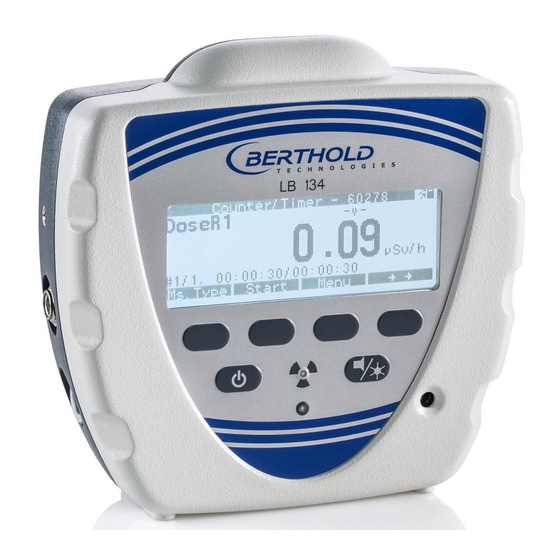
LB 134 4. Software Design and Operation 4.2 Measurement Menu Display The Measurement menu appears a) immediately after switching on the device or b) by pressing ESC on the System menu. We have chosen a dose rate measurement as an example. - Page 42 LB 134 4. Software Design and Operation In the menu item Display Mode you can toggle between these modes of display. You can select additional information to the main display by briefly pressing the Info button in each of the three modes of display.
- Page 43 LB 134 4. Software Design and Operation Info button Press this button repeatedly and briefly to display additional in- formation on the ongoing measurement. Even after measure- ment end, further information is available for counter-timer and background measurement measurements. Depending on the measurement mode, the following additional information is displayed: Main display: - channel...
-
Page 44: Key Functions
LB 134 4. Software Design and Operation 4.3 Key Functions A long keystroke is identified by a double tone and by a brief flashing of the lower LED. Then you can release the button. The software is operated using the 4 push buttons in the mid- dle, below the display. -
Page 45: Operation
LB 134 4. Software Design and Operation Explanation of the example in Figure 4.3: Press the third button (Menu) to enter the System menu to se- lect the individual menus. Press the Meas. Type button repeatedly (if you are working... -
Page 46: Selecting Items From A List
LB 134 4. Software Design and Operation Proceed in the same manner with all digits of the desired number. Once all digits of the desired number have been entered, press Enter to confirm. Letters are entered in the same way (01234567890abc...z). -
Page 47: Led Indicators
LB 134 4. Software Design and Operation During parameter input Quit the edit mode by pressing Enter or Esc. Press Esc once more. This will bring you to the one next menu in the menu tree until you get to the System Menu. -
Page 48: Contamination Measurements
LB 134 5. Contamination Measurements Contamination Measurements In this chapter we will discuss the contamination measurement, which is representative of the performance of other measure- ments. Other measurements, for example, activity measure- ments of samples or dose rate measurements, are very similar, but they still differ in some respects. -
Page 49: Requirements For Contamination Measurements
LB 134 5. Contamination Measurements 5.1 Requirements for Contamination Measurements 5.1.1 Function Check Turn the device on and make sure sufficient battery capacity is available. Warnings: If the battery/rechargeable battery voltage displayed after power on is below 4V for battery operation and below 4.5 V for rechargeable battery operation, the remaining battery life is 2-4 hours max.! - Page 50 LB 134 5. Contamination Measurements Figure 4.6: Background menu for contamination probe Set the desired parameters for the background measure- ment. Background: - Shows currently stored background. It may come from a back- ground measurement or it can be entered manually.
- Page 51 LB 134 5. Contamination Measurements the background measured for both measuring channels is displayed. End of the background measurement: When the preset measuring time is over or by pressing the Stop button. The following softkeys are now enabled: Save the background, Start a new background measurement, back to the system Menu and Info.
-
Page 52: Creating The Small Nuclide Table
LB 134 5. Contamination Measurements Procedure Automatic background measurement after power on of the device. BG measurement finished (at the end of measurement or by pressing Stop) Saving the BG values Figure 4.9: Display at the end of a background measurement Press ESC twice to start the contamination measurement. - Page 53 LB 134 5. Contamination Measurements If the nuclide or nuclide mix to be measured is not yet included in the small nuclide table, proceed as follows Select Nuclides on the System Menu. Figure 4.11: System menu Press the Enter key. The nuclide table is displayed. The nu- clides contained in the small nuclide table are marked with an X.
-
Page 54: Importance And Editing The Other Nuclide Parameters
LB 134 5. Contamination Measurements 5.1.4 Importance and Editing the Other Nuclide Parameters In addition to the activation of a nuclide, there are the following parameters: Figure 4.13: The parameters of a nuclide Edit procedure Move the cursor (->) to the desired menu item. -
Page 55: Measurement Of Contaminations
LB 134 5. Contamination Measurements Cal. Factor ISO Calibration factor according DIN ISO 7503-1 Alarm Threshold: Alarm threshold for visual and audible alarm in the same unit as above Integral Threshold: Threshold for the integral value of the measurement unit... -
Page 56: Cps Measurement
LB 134 5. Contamination Measurements Each display shows the currently measured value, the unit of measurement and, on the left, the selected nuclide and the measurement mode. The measured value for the new setting is displayed virtually with no time delay whenever there is a change in display. - Page 57 LB 134 5. Contamination Measurements In the Display Mode menu you can change the display lay- out. Then select the nuclide to be measured: If two measuring channels are displayed, press the Nuclides key first. Then the function of the softkey changes.
-
Page 58: Explanations On Raw Data And Calculated Units
LB 134 5. Contamination Measurements 5.2.3 Explanations on Raw Data and Calculated Units In this chapter you will learn to choose the appropriate meas- urement mode for each situation, and what differences there are between the individual modes: Net [cps]... -
Page 59: Measured Result As A Function Of The Contaminated Surface
5.3 Measured Result as a Function of the Contaminated Surface The calibration factors for the Bq/cm² display determined at the factory and stored in the LB 134 in the setting A-100 (according to DIN 25415) refer to calibration sources having the dimen-... -
Page 60: Exceeding Of Limit Values
LB 134 5. Contamination Measurements a) whether the same radionuclide has been set, and b) whether the source used for calibration meets the above mentioned requirements. When measuring area contaminations, the extent of the con- tamination relative to the standardized area of the calibration source of 100 cm²... -
Page 61: Software Functions
LB 134 6. Software Functions Software Functions In this chapter you will find information on all measurement functions, parameters and service functions in the order they appear on the System Menu. It starts with the description of the actual measurement of contamination, activity or dose rate. - Page 62 LB 134 6. Software Functions System Menu Options Live Display Measurement Use Int. DR-Det. OFF, ON Background Start Measuring BG Alpha/ BG Beta-Gamma Meas. Time Autostart OFF, ON Meas. Mode Ratemeter, Counter-Timer, Search Meas. Parameters Meas. Time Cycles Avg. Mode...
- Page 63 LB 134 6. Software Functions If you press the double arrow key on the right once more, fur- ther functions appear in the bottom line. If you press this key once more, the first functions appear again (see first picture).
-
Page 64: Description Of The Individual System Menu Items
LB 134 6. Software Functions Reset This button resets the Ratemeter parameters, such as min/max values, cycle storage time, smoothing filter parameters. ∫Start Starts the integral calculation, summing up of the measured values; for dose rate it starts the dose calculation, start of the integral time. -
Page 65: Use Internal Dr Detector
LB 134 6. Software Functions Figure 6.2: System menu for alpha-beta probe 6.3 Use Internal DR Detector If the checkbox to the right in this menu row is ticked, this means that the internal dose rate probe is used, even when the external probe is connected. - Page 66 LB 134 6. Software Functions The functions and settings are explained below: Figure 6.4: Background menu with options for the contamination probe The currently stored background is always subtracted from each measurement (in each measurement mode). Start measurement Starts the background measurement in one or both measuring channels simultaneously –...
- Page 67 LB 134 6. Software Functions a) The info line can be used while a measurement is running to view the accuracy or the time and date. b) At the end of the measurement, the backgrounds ( and ) can be saved (Save button) and information on the meas- urement can be viewed (Info button).
- Page 68 LB 134 6. Software Functions Measuring time [s] Enter the measuring time in seconds. It should be at least 60 seconds to obtain accurate measurement results. Note that the preset measuring time limits the background measurement, no matter what accuracy is reached! The actual measuring time can be viewed by pressing the Info button.
-
Page 69: Measurement Mode
LB 134 6. Software Functions 6.5 Measurement Mode In this menu, you can select three different averaging methods for the measurement results: Counter/Timer, Ratemeter and Search Mode. The associated parameters are set in the Measurement Parameters menu. The selected averaging mode is retained even after the device has been powered off and on again. - Page 70 LB 134 6. Software Functions Figure 6.7: Parameters for Ratemeter measurements Avg. Mode Set the type of averaging. You can select Time Constant or Accuracy. Time Const. Enter the desired time constant, i.e. the time to be used to smooth the measured values.
-
Page 71: Counter/Timer
LB 134 6. Software Functions 6.6.2 Counter/Timer If you select the measurement mode Counter/Timer, you will see the following options: Display for alpha beta contamination probe. Display for dose rate probe. Figure 6.8: Parameters for a Counter/Timer measurement, for two different probes ... -
Page 72: Search
LB 134 6. Software Functions copied to a memory stick and transferred to a PC. The current saving process is displayed in the upper left corner of the dis- play. Auto Send Enable (X) or disable ( ) the automatic transfer function via USB to the PC. - Page 73 LB 134 6. Software Functions leted. The following three displays show the first 12 nuclides for an alpha beta contamination probe. Figure 6.10: The first twelve nuclide entries for alpha-beta probe The next two displays show examples of measurement types for a dose rate probe.
- Page 74 LB 134 6. Software Functions "α-tot" and " -tot". In addition, it includes the units Net [cps] and Gross [cps] for alpha and beta-gamma SOURCES. The following information is included for each nuclide: name, active, radiation type, mass number, unit, two calibration factors...
- Page 75 LB 134 6. Software Functions Figure 6.13: Measurement type parameters for a dose rate probe The following information is included for each measurement type: name, active, radiation type, the order in the list, unit, one calibration factor, one alarm threshold for the measured value,...
- Page 76 LB 134 6. Software Functions The parameters in detail: Name Nuclide name. Active Change the status to passive or active. Shows the type of radiation of the nuclide ( or orγ or n). Radiation type Mass number Physical mass number of the nuclide or order of the measure- ment type (1, 2, 3, ……)
-
Page 77: Integral Reset
LB 134 6. Software Functions Sr-90: 1 When the limit value is exceeded, measures have to be tak- en immediately to avoid the spreading of the contamination (German Radiation Protection Ordinance § 44). Moreover, the measured value has to be recorded in this case. -
Page 78: Display Mode
LB 134 6. Software Functions 6.9 Display Mode You can select one of three possible display modes for a con- nected alpha beta contamination probe. Figure 6.16: Selection options in the display mode In the first case, the alpha and beta channel are shown the same size. -
Page 79: Upload And Download Memory And Parameters
Berthold PC program LB 134, the parameters can be written to the USB stick from a file and then transferred to a LB 134 with the stick. On the other hand, the pa- rameters on the USB stick can be read and archived by this PC program. - Page 80 LB 134 6. Software Functions The measurements are stored in the order they have been saved in the RAM memory. The pages are numbered consecu- tively; one page is used for each measured value. Figure 6.20: Options on the Memory menu ...
- Page 81 LB 134 6. Software Functions Memory contents of dose rate probe in Counter/Timer mode Figure 6.21: Examples for Show Memory menu To go to the desired results, you have the following options: ↓↑ key: short push: Next measurement ↓↑ key:...
-
Page 82: Parameters
If the memory with the time information is deleted (e.g. by stor- ing the LB 134 without batteries), the date and time will be au- tomatically queried when the device is turned on. The entry is made as shown below: DD.MM.YYYY or HH:MM:SS. -
Page 83: Language
6.11.3 Device Address Enter a device address between 1 and 255 for networking with the RS485 bus. If the LB 134 receives a command via the USB or RS485 interface, the address contained therein must match the above address for the command to be processed. -
Page 84: Power Supply
Figure 6.32: Display when working with rechargeable batteries Battery Type: Battery or Accu Here you can specify whether the LB 134 should work in the battery or rechargeable battery mode. If Accu is set, the pa- rameters Charge Mode and Charge Time are displayed as well. -
Page 85: Hardware
6. Software Functions the power supply is connected directly to the device and the LB 134 is turned on. To this end, the Charge Mode must be set to On (X). The menu item Charge Time allows you to limit the duration of the charg- ing process to 12 hours max. - Page 86 The serial number of the detector is entered at the factory or taken from the probe. Ser. No. Device: The serial number of the LB 134 device is entered at the facto- ry; it cannot be edited. Control Voltage (V): For many probes, the control voltage is not needed for the probe high voltage, with a few exceptions.
- Page 87 LB 134 6. Software Functions Baud Rate: The baud rate for the USB interface is always 38400 baud and cannot be changed. The baud rate for the RS485 interface can be set between 2400 and 38400 and depends on the length of the data cable and the number of connected devices.
-
Page 88: Factory Setting
LB 134 6. Software Functions is carried out at the end of fail time and, where appropriate, the error message "Failure" is output. Then this measurement will start new. See section: 1.7 for information on how to calculate the values. -
Page 89: Ticks
LB 134 6. Software Functions Figure 6.34 Alarm settings If the alarm is set to Acoustic or Optical/Acoustic, you will hear, in addition to the visual alarm, an acoustic signal when the threshold is exceeded. The respective threshold is stored spe- cific to the nuclide or specific to the measurement mode in the nuclide/measurement type table and can be edited. -
Page 90: Enable Menus
LB 134 6. Software Functions 6.14 Enable Menus To simplify handling, the device allows you to hide single or all menus for the measurement operation. On the other hand, the menus can be enabled to view only the parameters or to view and edit the parameters. -
Page 91: Probes For The Lb 134
7.2 Scintillator Probes with ZnS for Contamination Measurements In this chapter we will describe the Berthold scintillation probes designed for the measurement of alpha, beta and gamma con- tamination in detail. - Page 92 LB 134 7. Probes for the LB 134 Using special evaluation and correlation circuits, the individual types of radiation such as alpha and beta/gamma/X-ray radia- tion are distinguished, separated and measured simultaneously (patented by B ). Part of the spillover of...
-
Page 93: Cleaning The Detector Window Of Contamination Probes With Scintillator
LB 134 7. Probes for the LB 134 Figure 7.2: LB 1343, scintillation probe with 345 cm² The scintillator is applied on a transparent carrier. The foil is stretched over a frame and protected by a metal grid. The de- tector is fixed to the underside of the cover with four screws. -
Page 94: Changing The Window Foil Of Contamination Probes With Scintillator
LB 134 7. Probes for the LB 134 7.2.2 Changing the Window Foil of Contamination Probes with Scintillator A damaged detector window foil can easily be replaced by the user. B supplies a foil stretched over a ERTHOLD ECHNOLOGIES frame as spare part. - Page 95 LB 134 7. Probes for the LB 134 Technical data: Sensitive LB 1342:118mm x 145mm, 170 cm² detector area LB 1343: 150 mm x 230 mm, 300 cm² Entrance Layer thickness: 6um window Weight per unit area: 0.4 mg/cm² Geometric...
-
Page 96: Contamination Probes Lb 1231 And Lb 1233
LB 134 7. Probes for the LB 134 7.3 Contamination Probes LB 1231 and LB 1233 Two different hand probes as proportional counters are availa- ble for contamination measurements: 1. LB 1231 with beta-gamma-xenon detector LB 6357 2. LB 1233 with alpha-beta-P10 gas flow counter tubes LB... - Page 97 The connected probe type is transferred to the soft- ware program in the LB 134 and there it activates the respec- tive parameters and calibration factors. Figure 7.5: Protective case (bottom view)
-
Page 98: Lb 1233 With Alpha-Beta P10 Counter Tube Lb 6359 And Refill Station
LB 134 7. Probes for the LB 134 Both counter tubes consist of a gas-filled counting chamber with counting wires. The counter tubes incorporate the necessary electronics such as amplifier and high voltage generator; there- fore, the plug-in connection between the case (hood) and the detector does not carry any high voltage, so there is no hazard in touching it. - Page 99 LB 134 7. Probes for the LB 134 A P10-gas cylinder (local) with double pressure reducer or a central P10 gas supply can be used to flush and fill the detec- tor. The P10 gas is a gas mixture consisting of 90% argon and 10% methane.
- Page 100 LB 134 7. Probes for the LB 134 All valves close automatically when the detector is lifted off the bracket; this stops the gas supply and keeps the P10 gas in the counting chamber. The operation life after filling or flushing is at least 8 hours with a loss in efficiency of less than 5 %.
- Page 101 LB 134 7. Probes for the LB 134 valve opener in a safe place and use it for transportation or storage. 2. Using the screws and dowels supplied with the instrument, install the wall bracket for the detector LB 6359 on a vertical wall in a convenient height.
- Page 102 LB 134 7. Probes for the LB 134 and ready for operation (operation time at least 8 hours with a loss in efficiency of less than 5 %). Replacing the window foil of αβcounter tubes A spare foil on a frame is standard accessory for this counter tube.
-
Page 103: Lb 1231 With Beta-Gamma Counter Tube Lb 6357
The window foil (5 mg/cm² Titan foil) can only be replaced by Berthold. However, the mesh grid frame can be removed to clean the foil. -
Page 104: Dose Rate Probe Lb 1236-H10
7. Carefully install counter tube; do not twist or jam the coun- ter tube cable. 8. Close snap locks without force. After power on, the LB 134 microprocessor identifies the connected probe and sets its program and all calibration factors, alarm thresholds, etc. accordingly. - Page 105 Background sub- menu. Connect the detector with the 8-pin connector Fischer to the turned off LB 134. After power on of the LB 134, the connected detector is checked and identified by the software, and the re- spective parameters are loaded.
-
Page 106: Neutron Dose Rate Probe Lb 6411
He recoil proton counter tube at its center. The probe also includes the high voltage supply and a pream- plifier. It can be connected directly to the LB 134 UMo II. In the energy range between 1 and 10 MeV the sensitivity is about 3 counts per nSv. -
Page 107: Neutron Survey Meter Lb 6414
LB 134 7. Probes for the LB 134 level, the extremely low background of 0.05 cps permits reliable measurements of 0.1 µSv/h. The upper limit of the measuring range is 100 mSv/h. Technical data: Unit of measurement: Ambient dose equivalent rate H*(10) -
Page 108: Nal Scintillation Counter Probe Lb 1234
The universal battery-powered monitor LB 134 with data storage and adjusta- ble alarm is used as measuring and display system. -
Page 109: Activity Probe For Solid Samples Lb 1238
LB 134 7. Probes for the LB 134 Figure 7.14: NaI Scintillation Probe LB1234 for the LB134 Technical data: 1“ x 1“ NaI crystal Scintillator: γ-response: 250 cps per μSv/h in Cs radiation field 3000 cps per μSv/h in Am radiation field Background: approx. - Page 110 LB 134 7. Probes for the LB 134 Figure 7.15: Lead shielding and activity probe LB 1238 Technical data: Detector: Proportional end window counter tube Entrance window: Mica window, about 2 mg/cm² Energy range: Alpha: from 3 MeV Beta: from 40 keV Responsiveness: Am-241 approx.
-
Page 111: Tritium Surface Contamination Monitor
The Tritium Surface Contamination Probe LB 1239 consists of the following parts: Windowless Tritium probe LB 1239 with combined spiral ca- ble/gas tubing for connection to the LB 134 and gas supply (8-pin to 11-pin spiral cable and transparent PVC tubing with 3 mm internal diameter) Figure 7.17: Tritium probe LB 1239... -
Page 112: Application
The Tritium probe incorporates a preamplifier and a high volt- age generator; for measurement, it simply has to be connected to the basic LB 134 unit via a 8-pin cable and a P10 gas supply tubing. The user-friendly assembly of the instruments on a trolley with... -
Page 113: Counting Gas Supply
Figure 7.19: The window side of the Tritium probe LB 1239. The Tritium probe is connected to the basic unit LB 134 using a spiral cable; the LB 134 automatically identifies the probe after power on, switches to the CPS mode and takes over the HV control. - Page 114 LB 134 7. Probes for the LB 134 This ensures that only the required amount of counting gas is consumed and that the cylinder valve need not be opened and closed after each measurement. The rotameter shows a gas flow of 0 - 3000 cm³/min. For measurement, the gas flow should be set to 2000 cm³/min.
-
Page 115: Tritium Probe With Trolley
In the center of the console there are two retention cradles, in- to which the LB 134 is placed and secured by knurled screws. The rotameter indicating the actual gas flow is installed to the left of the Tritium probe. -
Page 116: Commissioning Of Tritium Probe
LB 134 7. Probes for the LB 134 b) You may also proceed in reverse order: First, put the front side of the probe against the pivots and then push the rear side down against the tapered bar. Figure 7.22: Inserting the Tritium probe Figure 7.22: Closing the gas valve when inserting the probe... - Page 117 9. Using the spiral cable, connect the LB 134 and the Trit- ium probe. The 11-pin socket of LB 134 is located on the right side of the instrument, that of the probe on the front side facing the user.
- Page 118 Using the β-γ-probe On the left side of the trolley console there is space for the β-γ probe LB 1231; its connecting cable to the LB 134 is placed in a holder. Turn off the LB 134.
-
Page 119: Practical Hints For Operation And Measurement
7.9.7 Practical Hints for Operation and Measurement Operation with LB 134 The measurement of Tritium with the LB 134 and the connected Tritium probe is carried out in the same manner as the contam- ination measurement described above. Probe and calibration factors are set such that only Tritium activities are determined and displayed. -
Page 120: Efficiency And Detection Limits
H, one will measure about 85% of the emitted particles. 7.9.9 Efficiency and Detection Limits Detecting H Contamination There is no completely satisfactory method for detecting contamination. The following options are available: Direct measurement using the Monitor LB 134/LB 1239... - Page 121 LB 134 7. Probes for the LB 134 Wipe test (using glycerin or toluene-saturated filter papers, then measurement with the probe LB 1239 or in a liquid scintillation counter) Washing down or rinsing clothing, followed by measuring liquid samples in the liquid scintillation counter.
-
Page 122: Working With The Β-Γ-Probe
0.015 Bq/cm² approx. 0.04 10E-5μCi/cm² *) With the LB 134 the time constant in the normal measurement mode is 120 s. The Counter/Timer mode can be used for more accurate measurements. The limit threshold for 5 Bq/cm... - Page 123 2. Pull out the spiral cable connecting the Tritium probe to the LB 134. 3. Insert the spiral cable of the β-γ-probe into the LB 134 sock- 4. Turn the LB 134 on. The software identifies the connected β- γ-probe and sets the measurement mode accordingly.
-
Page 124: Maintenance
LB 134 8. Maintenance Maintenance 8.1 Battery Replacement The device requires four AA dry batteries, Mignon with 1.5 volts or 4 Mignon rechargeable batteries with 1.2 volts. The operating time with a new set of batteries is longer than 15 hours of con-... -
Page 125: Charging Rechargeable Batteries
(eneloop Pro AA 2450 mAh). Select the battery type "Accu" on the menu Parameters/Power Supply. Connect the LB 134 to the power supply to charge the batteries (the device is switched on automatically) and the charge pro- cess starts if the parameters in the menu Parameters/Power Supply/Charge Mode have been set accordingly. -
Page 126: Basis Of Calculation
9. Basis of Calculation Basis of Calculation 9.1 Calculating the Count Rate The LB 134 updates the calculation of the raw data in CPS (counts per second) every second, i.e. the further calculation is based on 1 second intervals. General Formulas and Terms... -
Page 127: Ratemeter Function
LB 134 9. Basis of Calculation 9.2 Ratemeter Function The weighting factor W described in chapter 9.1 can be deter- mined either as a function of the time constant or the accuracy: a) Preset time constant: The number of seconds entered indicates the maximum time... -
Page 128: Search Mode
LB 134 9. Basis of Calculation Definition of statistical errors: Formula abs. error rel. error R Gross count rate R Net count rate ... -
Page 129: Counter/Timer Function
LB 134 9. Basis of Calculation Basis of calculation: Designation Variable Unit Default Parameters Time constant (preset time) Sigma factor Nuclide (with calibration factor K) Preset time constant: t t R Reset and recalculate of 9.4 Counter/Timer Function... -
Page 130: Determination Of Calibration Factors In The Event Of Contamination
determine calibration factors for other nuclides for contami- nation measurements, which are not included in the nuclide library of the LB 134. New nuclides can be added to the nu- clide list. To convert counts per second into decays per second per cm... - Page 131 LB 134 9. Basis of Calculation Source Bgrd (1) (A in Bq) Detection Detection Surface Sample Bgrd Sample Bgrd Surface Detection The ISO calibration is performed according to the International...
- Page 132 LB 134 9. Basis of Calculation Proceed as follows 1. Select the CPS measurement mode. 2. Place the probe on the calibration source as centered as possible, so that as little as possible activity is lost. 3. Measure the calibration source with a measurement time of 60 seconds.
-
Page 133: Decision Thresholds And Detection Limits
LB 134. In the Counter/Timer mode, the calculation formula for activities, contamination and dose rate in the LB 134 is as follows (the units in all formulas are the same and depend on the measurement method, e.g. Bq/cm² or µSv/h, etc.): Basic formula for activity: ��... -
Page 134: Appendix
11. Appendix 11.1 Calibration Factors for LB 1342 Scint-Contamination Probe (170 cm²) List of radionuclides with calibration factors that are hard-coded in the LB 134 (for the scint detector) for the conversion of cps to Bq/cm . Test sources with a standardized area of 10 cm x 10 cm were used (A-100). The factors according to ISO 7503-1 have been determined in compliance with the requirements of the standard. - Page 135 200 s for the background and 30 s for the sample measurement 5) Background count rate used from 0.1 cps for alpha and to 10 cps for beta-gamma measurements 6) Valid from LB 134 software version 1.00...
- Page 136 LB 134 11. Appendix Efficiencies, response, calibration factors and Limit decision thresholds and detection limits LB 1342 values A-100 Decision Detection Efficiency Response Calibration threshold limit Nuclide factor in Bq/cm² s Bq cm 4)5) Bq/cm² Bq/cm² Beta 0.50 35.0 35.00 0.029...
- Page 137 200 s for the background and 30 s for the sample measurement 5) Background count rate used from 0.1 cps for alpha and to 10 cps for beta-gamma measurements 6) Valid from LB 134 software version 1.00...
-
Page 138: Calibration Factors For Lb 1231 And Lb 1233
LB 134 11. Appendix 11.2 Calibration Factors for LB 1231 and LB 1233 LB 1231 (Xenon) LB 1233 (P-10 Gas) A-100 – calibra- A-100 – cali- Nuclide Channel tion factor Channel bration factor in Bq/cm²/cps in Bq/cm²/cps α-tot Beta - Gamma Alpha 0.100... -
Page 139: Calibration Factors For Lb 1341 (Xenon Detector)
LB 134 11. Appendix 11.3 Calibration Factors for LB 1341 (Xenon detector) A-100 – calibra- ISO-7503-1 Nuclide Channel tion factor Calibration factor in Bq/cm²/cps in Bq/cm²/cps Beta-tot Beta - Gamma 0.042 0.028 C-11 Beta - Gamma 0.042 0.028 N-13 Beta - Gamma 0.037... - Page 140 LB 134 11. Appendix U-238 Beta - Gamma 0.025 0.061 Pu-238 Beta - Gamma 0.112 0.069 Pu-239 Beta - Gamma 0.152 0.100 Am-241 Beta - Gamma 0.089 0.056...
-
Page 141: Calibration Factors For Lb 1343, Scintillation Detector (345 Cm²)
LB 134 11. Appendix 11.4 Calibration Factors for LB 1343, Scintillation Detector (345 cm²) A-100 – calibra- ISO-7503-1 Nuclide Channel tion factor Calibration factor in Bq/cm²/cps in Bq/cm²/cps Beta - total Beta - Gamma 0.029 0.010 C-11 Beta - Gamma 0.027... - Page 142 LB 134 11. Appendix Am-241 Alpha 0.046 0.029 Po-210 Alpha 0.044 0.030 U-238sec Alpha 0.033 0.040 Pu-238 Alpha 0.045 0.028 Pu-239 Alpha 0.055 0.087 Am-241 Alpha 0.046 0.029 Alpha - total Alpha 0.050 0.033...
-
Page 143: F²C Communication Protocol And Commands
11. Appendix 11.5 F²C Communication Protocol and Commands The LB 134 has several communication options with the PC, via the USB port and via the RS485 interface. The baud rate for the USB interface is always 38400, for RS485 it can be set under Parameters/Hardware. - Page 144 LB 134 11. Appendix The individual characters are explained in the following table. Character no. Decimal Status Meaning value 0 / 1 Alarm Integral 2 on/off 0 / 1 Alarm Integral 1 on/off 0 / 1 Alarm measured value 2 b on / off...
-
Page 145: Transmission Protocol
(Minimum length = 20, maximum 255) The stars "*" must always be included, even if CSM is empty. The LB 134 answers, with TDV and FDV being exchanged in the frame. The LB 134 does not respond to request, if 1. -
Page 146: Command Overview
LB 134 11. Appendix 4. MBR = channel of a processor 1,2,3 = digital inputs 1,2,3,4,5 = fault outputs 1.2 = analog outputs 5. TYPE = type of request 00 = not connected 01 = measured results 02 = measuring parameters 03 = execute action 6. - Page 147 LB 134 11. Appendix Data Comment ----------- and TDV=0000, DevID will be send Current detector index (1..N) Brightness of display (1,2,3) ----------- Read Date Time dd/mm/yy hh.mm.ss Set Date Time Set language (1 = deu, 2 = engl) Set autosave (0, 1)
- Page 148 LB 134 11. Appendix Parameters Data Comment In the following, nn will be used as detector type: nn = 1..20 NNNN Set sample measurement time in sec NNNN Set background measurement time in sec Set measurement mode (1=RM, 2=ZT, 3=S)
- Page 149 Numerical input in exponential presentation possible, for example, 1.3E06. Error messages: Instead of the data, error messages from the LB 134 may be displayed (message instead of data): Data have no meaning, for example: b values in only a channel for a/b detector.
- Page 150 Data memory read pointer has reached the write pointer. Separator between response data is the colon. Example of frame with F2C protocol: Command: Get current or oldest FIFO element for all probes Command to LB 134: *0001900101010100**CR Response from LB 134: *900100010201010022.02.201517:50:03:0037:0002:002024040000:0030:Netto:0:cps:0:cts:DosisL1:0.106536 :µSv/h:0.000387:µSv:0.003056:0:0:0:0.07:0000:LB1346*70*...
- Page 151 LB 134 11. Appendix With LB 1342 Alpha-Beta contamination probe, Counter/Timer, 10s measuring time, 3 cycles Explanation: LB1342 (1) (LB Number of probe) 22.02.2015, 16:36:03 (Date and Time) (Background and BG Time) Netto 1.000 100.0 0.6300 (C-Factor and alarm threshold) Netto 1.000...
-
Page 152: Parameter Locking With Jumper J3
LB 134 11. Appendix 11.6 Parameter Locking with Jumper J3 There may be the need, with the internal and external dose rate probe, to protect certain parameters from being changed by means of a hardware interlock, e.g. calibration factor, back- ground, dead time. - Page 153 3 pin jack plug socket Connection for standard headphones, 3 pin For 3.5 mm diameter plug 3 pin power supply connector, socket Please use only Berthold power supply, 6 VDC, 1.5 A USB host connector To connect a USB memory stick USB device connector...
-
Page 154: Example Of Rs485 Network With Multiple Lb 134 As Dose Rate Monitor
LB 134 11. Appendix 11.8 Example of RS485 Network with Multiple LB 134 as Dose Rate Monitor S485 to USB Earth (Ground) or RS232 adapter 120 Ohm Connection boxes Additional monitors (up to 31) Shielded twisted pair cable 120 Ohm Cable length: <... -
Page 155: Technical Data Lb 134 Umo Ii
Primary voltage: Wide range input 90-264VAC 50/60 Hz Output voltage: 6V, 1.5A Operating time 1.9 Ah Ni-MH rechargeable batteries, LB 134 + internal DR: 10 h 2.6 Ah batteries, LB 134 + internal DR: 15 h Communication USB interfaces: Host for USB stick, device for PC connection Meas. -
Page 156: Index
LB 134 13. Index 13. Index CPS measurement Creating the small nuclide table Accessories Accuracy (Ratemeter) Alarm thresholds Data interface Alarm type Date/Time Audible warning signal Decision thresholds Auto Save 60, 61 Delete memory Auto Send 60, 62 Design and mode of operation of the... - Page 157 LB 134 13. Index Lithium backup battery Ratemeter Ratemeter function Ratemeter mode Mains operation Rechargeable batteries 16, 74 Maintenance Replacing the foil! Measured value storage Measurement Measurement menu 17, 31 Safety Instructions Measurement mode Sandwich detector Measurement modes 9, 48...
Need help?
Do you have a question about the LB 134 and is the answer not in the manual?
Questions and answers