
Subscribe to Our Youtube Channel
Related Manuals for Berthold MicroPolar Brix ++ LB 565


Summary of Contents for Berthold MicroPolar Brix ++ LB 565
- Page 1 Concentration Meters MicroPolar Brix (++) LB 565 User’s Guide Hardware Manual 39531BA2 Rev. Nr.: 08, 07/2023...
- Page 4 The units supplied should not be repaired by anyone other than Berthold Technolo- gies Service engineers or technicians by Berthold Technologies. In case of operation trouble, please address to our central service department (ad- dress see below). ’ The complete user s guide consists of the hardware manual and the software manual.
-
Page 5: Table Of Contents
Table of Contents Table of Contents Page Chapter 1. Safety Summary 1.1 Symbols and Warnings 1.2 General Information 1.3 General Safety Instructions Chapter 2. General Information 2.1 Use and Function 2.2 Frequency license 2.3 Intended Use 2.4 Explanation of Terms Chapter 3. - Page 6 Table of Contents Chapter 7. Certificates 7.1 EC Declaration of Conformity 7.2 Frequency License Chapter 8. Technical Drawings 8.1 Dimensional Drawings of Evaluation Unit Housing 8.1.1 Evaluation Unit for MicroPolar Brix 8.1.2 Evaluation Unit for MicroPolar Brix ++ 8.2 Electrical Wiring Diagram 8.3 Dimensional Drawings Flow Cells 8.3.1 Type LB 5660-102-00X FlowCell DN 50 Flange, FDA 8.3.2 Type LB 5660-202-00X FlowCell DN 65 Flange, FDA...
-
Page 7: Chapter 1. Safety Summary
Chapter 1. Safety Summary Chapter 1. Safety Summary 1.1 Symbols and Warnings In this user manual, the term Berthold Technologies stands for the company Berthold Technologies GmbH & Co.KG. To rule out bodily injury and property damage, please keep in mind the warning and safety instructions provided in this user manual. -
Page 8: General Information
Chapter 1. Safety Summary Meaning of other symbols used in this documentation: Warning: No intervention, do not alter anything Requirement: Disconnect power Requirement: Wear safety boots 1.2 General Information The most important safety measures a summarized in this user manual. They supplement the corresponding regulations which must be studied by the personnel in charge. -
Page 9: General Safety Instructions
Chapter 1. Safety Summary 1.3 General Safety Instructions IMPORTANT The equipment housings have IP 65 protection and are suitable for outdoor applications. The units are factory tested and are delivered in a condition that permits safe and reliable operation. For outdoor applications, the measuring systems must be protected from direct sunlight and rain, for example by a suitable shelter. - Page 10 Chapter 1. Safety Summary Electrical hazards Disconnect power to ensure that contact with live part is avoided during installation and when servicing. Disconnect the power supply before opening the instrument. Work on open and live instruments is prohibited. Caution! Potential hazards, material damage! Device type: LB 565-12 MicroPolar Brix ++ (ID no.
-
Page 11: Chapter 2. General Information
The use after repair by persons not authorized by Berthold Tech- nologies. The use in a damaged or corroded state. -
Page 12: Frequency License
Chapter 2. General Information 2.2 Frequency license This device complies with Part 15 of the FCC Rules and with In- dustry Canada licence-exempt RSS standard(s). Operation is subject to the following two conditions: this device may not cause harmful interference, and this device must accept any interference received, includ- ing interference that may cause undesired operation. - Page 13 Consult the dealer or an experienced radio/TV technician for help. Changes or modifications made to this equipment not expressly ap- proved by BERTHOLD TECHNOLOGIES may void the FCC au-thori- zation to operate this equipment. The MicroPolar Brix and MicroPolar Brix ++ comply with the R&TTE Directive 1999/5/EC and thus meet all the requirements for this type of high-frequency devices.
-
Page 14: Intended Use
Chapter 2. General Information 2.3 Intended Use The measuring system LB 565 can be used to determine the con- centration of nearly all materials that are dissolved or suspended in water by means of microwave technology. The following sensors and evaluation versions are available: The container probes have been designed for installation into pipelines with a nominal diameter ≥... -
Page 15: Explanation Of Terms
Chapter 2. General Information 2.4 Explanation of Terms Attenuation Weakening of microwave signals, microwaves measuring effect. Conti probe Container probe with flushing device. Application e.g. continu- ous evaporative crystallization process. Disconti probe Container probe without flushing device. Application e.g. evapo- rative crystallization process. -
Page 17: Chapter 3. System Description
Chapter 3. System Description Chapter 3. System Description 3.1 Principle of Measurement As the microwaves pass through the product, their propagation ve- locity is slowed down (= phase shift) and their intensity is attenu- ated (= attenuation). Figure 3-1 illustrates the principle of meas- urement: Compared to a reference signal, the propagation velocity of microwaves passing through the product is slowed down (phase shift) and their intensity (attenuation) is reduced. -
Page 18: Calculation Of Measured Values
Chapter 3. System Description 3.2 Calculation of Measured Values The microwave parameters phase and attenuation are calibrated according to an automatic plausibility analysis. During calibration, the phase and/or attenuation of a concentration value (or density value) are assigned through sampling. The cali- bration is done automatically and the sampling process is sup- ported by the evaluation unit. -
Page 19: Temperature Compensation
Chapter 3. System Description 3.3 Temperature Compensation Temperature compensation (TC) is required for fluctuating product temperature. It is generally advisable to provide a temperature compensation, i.e. a temperature signal (0/4...20 mA or PT100) to be connected to the evaluation unit and, optionally, to enable the compensation in the evaluation unit. -
Page 20: Mechanical Components
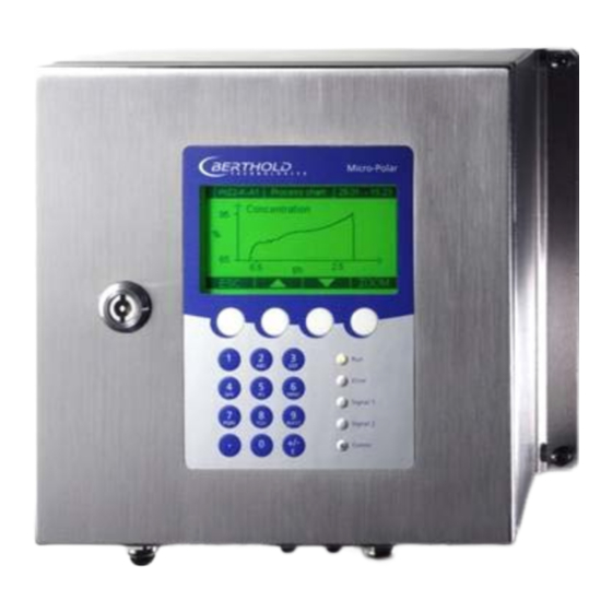
(short HF cable). The evaluation unit is available in two versions: the standard model MicroPolar Brix LB 565 and the high dynamics version MicroPolar Brix ++ LB 565 (see Figure 3-2 and Figure 3-3). Figure 3-2:... -
Page 21: Evaluation Units
Chapter 3. System Description The probes are available in different versions, as pipeline and con- tainer probe with or without flushing device (see Figure 3-4 and Fig- ure 3-6). Figure 3-4: Container probe LB 5650 Figure 3-5: Container probe with flushing device LB 5651 Figure 3-6: FlowCell LB 5660-102-00x... - Page 22 Chapter 3. System Description Differences between MicroPolar Brix ++ und MicroPolar Brix The MicroPolar Brix ++ evaluation unit has an additional HF ampli- fier module in comparison to the standard model; therefore, it also has a larger wall housing (dimensions see chapter 6.2 Technical Data Evaluation Unit).
- Page 23 Chapter 3. System Description LED’s on the Front Panel ’ Five LED s on the instrument front panel indicate the current device status. Error Signal 1 Signal 2 Figure 3-9: LEDs on the front panel Comm of the evaluation unit Function On: Device in measurement mode Flashes + ERROR LED off: Device in warning...
-
Page 24: Flow Cell
Chapter 3. System Description 3.4.2 Flow Cell The FlowCell is available in the nominal sizes of 50 to 150 mm (see fig. 3-11). As connection, the versions V flange EN 1092-1/11 or Hygiene milk pipe screw connection DIN 11853-1 are available. For technical data please see chapter 6.2 Technical Data Sensors. - Page 25 Chapter 3. System Description Rx). The microwave signals transmit the product over the entire pipeline cross-section. For all versions, the following accessories are available: 1. Pipe-mounted PT100 or Inline PT100 2. Conductivity measuring device 3. Sampling valve (combination with 1. and 2. possible) Overview accessories (see also chapter 6.2): Conductivity measuring device...
- Page 26 Chapter 3. System Description Sampling valve Combination Conductivity measuring device with Sampling valve Combination Inline PT100 with Sampling valve MicroPolar Brix (++) LB 565...
-
Page 27: Container Probe
Chapter 3. System Description 3.4.3 Container Probe The container probe is available in a version with and without flush- ing device (see Figure 3-11). The technical data are listed in chapter 6.2 Technical Data Sensors. Figure 3-11: Container probe versions A: High-frequency ports B: Process connection, flanges of different sizes Container probe type LB 5650 and type LB 5651... - Page 28 Chapter 3. System Description Two different probe types are available: The standard type is the container probe without flushing device. The flushing probe is used in processes where incrustations are likely to occur, for example, due to increased depositions. The flushing device prevents deposition on the microwave exit win- dows.
- Page 29 Chapter 3. System Description Warning: Possible material damage! Do not open the cover screws on the front of the container probes, see Figure 3-13. Figure 3-13: Front view container probe Container probe type LB 5651 with flushing device The flushing probe LB 5651 has been designed for processes in which depositions, for example, due to incrustations are likely to occur on the probe.
- Page 30 Chapter 3. System Description Figure 3-14: Flushing probe LB 5651 The flushing slit width is the same for both probe rods and is de- picted in Figure 3-15 Flushing pipe Plastic rods Figure 3-15: Rod head with flushing pipe MicroPolar Brix (++) LB 565...
-
Page 31: High-Frequency Cable
Chapter 3. System Description 3.4.4 High-frequency Cable High-frequency cables (HF cable) are used to transmit microwaves between probe and evaluation electronics. HF cables change their conductivity (for microwaves) with temper- ature and would therefore produce measurement errors with vary- ing ambient temperature. This error is compensated for by enabling the automatic cable compensation. - Page 32 Chapter 3. System Description 4 x N-connector 4 x N- 4 x N-connector ø 18.5 mm Corrugated tube 0.35 m 0.35 m Lengths 2 to 10 m Figure 3-16: HF cable Quad Sensor side N-connector (ID-No. 20608) Figure 3-17: HF cable Quad probe side: Figure 3-17: The ends of the reference line R-Rx and R-Tx are short- circuited with an N-connector.
-
Page 33: Measurement Assembly On A Pipeline
Chapter 3. System Description 3.5 Measurement Assembly on a Pipeline The evaluation unit is installed close to the FlowCell to keep the HF cable between evaluation unit and probe as short as possible. The shorter the cable connection, the better the stability of the meas- urement. -
Page 34: Measurement Assembly On A Container
Chapter 3. System Description Measurement Assembly on a Container The evaluation unit is installed in close proximity to the container probe to keep the HF cable between evaluation unit and probe as short as possible. The shorter the cable connection, the better the stability of the measurement. -
Page 35: Chapter 4. Getting Started
Chapter 4. Getting Started Chapter 4. Getting Started 4.1 Transport Warning: Possible material damage! System parts may get damaged during transportation! The probe and the evaluation unit should be transported in their original packaging. Protect parts against shocks. Especially the measuring rods of the container probes have to be protected against mechanical shock! After unpacking, make sure all parts listed on the packing list have been delivered and show no sign of damage;... - Page 36 Chapter 4. Getting Started Do not use aggressive cleaning agents or chemical which can af- fect the product contact surface. The customer is obligated to clean the FlowCell appropiately be- fore it comes into contact with food. To meet the requirements for EHEDG certification, the sensor must be connected with process connections in accordance with the EHEDG position paper entitled "Easy Cleanable Pipe Couplings and Process Connections"...
-
Page 37: Container Probe Installation
Chapter 4. Getting Started Abb. 4-2: Horizontal installation: The drainability of the pipeline must be respected. To en- sure this, the FlowCell must not be rotated. 4.2.2 Container Probe Installation Danger of injury from leaking operating medium. The Container probe must be mounted correctly. In particular, the correct tightening torque for the flange screws must be observed. - Page 38 Chapter 4. Getting Started Select the installation site such that a good mixing and a homo- geneous product are ensured and no bubbles are present in the probe. A sample tap should be available for representative sam- pling in the immediate vicinity. ...
- Page 39 Chapter 4. Getting Started Installation on process containers Figure 3-19 shows the position of the container probe on the con- tainer. This position is also valid for the container flush probe. Fol- low the instructions in chapter 3.6 Measurement Assembly on a Container.
-
Page 40: Setting Up The Evaluation Unit
Chapter 4. Getting Started The following product and process independent flushing parameters must be strictly adhered to: Flush solution Water, condensate Temperature of Maximum 120°C flush solution Pressure ≥ 3 bar, max. 8 bar Fittings 2 x G3/8'' female thread (DIN ISO 228-1) Supply pipe ≥... - Page 41 Chapter 4. Getting Started When installing the evaluation unit on a crystallizer, you should use a spacer rail to minimize the thermal radiation and conduc- tion. See Figure 4-3: For outdoor applications, the evaluation unit must be protected from direct sunlight and rain, for example by a suitable shelter.
-
Page 42: Connecting The Evaluation Unit
Chapter 4. Getting Started 4.3 Connecting the Evaluation Unit Connecting the HF Cable 4.3.1 You need the following HF quad cable to connect the sensor to the evaluation unit. For the flow cell Version 1: 1 x HF cable quad and 1 x N-connector Version 2: 2 x solid cables (as signal cable, same length) 1 x solid cable (as reference cable) - Page 43 Chapter 4. Getting Started Connecting the Flow Cell The HF cable quad and the HF connectors on the evaluation unit are Version 1 labeled. Connect the flow cell to the evaluation unit as shown in Figure 4-4; only cables with identical labeling can be combined. The two connections on the flow cell are not labeled, the assignment of both cable connectors M-Tx and M-Rx is arbitrary.
- Page 44 Chapter 4. Getting Started Connecting the container probes The HF cables and the HF connections on the evaluation unit and on the probe are labeled. Connect the probe to the evaluation unit as shown in Figure 4-6; only cables with identical labeling can be com- bined.
-
Page 45: Pin Configuration Of The Connector Strip
Chapter 4. Getting Started 4.3.2 Pin Configuration of the Connector Strip Electrical hazards Disconnect power to rule out any contact with live parts during in- stallation and servicing. Turn off power before opening the instrument. NEVER work on open and live instruments. Temperature signal connection A PT100 or a temperature current signal has to be connected to current input 1 or 2 if significant temperature fluctuations occur in... - Page 46 Chapter 4. Getting Started Other connections Connect all desired input and output signals to the terminal strip as shown on the following pages. Use the M feed-through to keep the degree of protection. Check if the voltage indicated on the type plate matches your local supply voltage.
- Page 47 Chapter 4. Getting Started Power supply: Terminals 3 (L1, +), 2 (N, -) and 1 (PE, For MicroPolar Brix, depending on device type, see name plate on the housing outer wall. 1.) 100…240 V AC, 45…65 Hz 2.) 24 V DC: 18…36 V 24 V AC: -20%, +5%, 40…440 Hz For MicroPolar Brix ++, depending on device type, see name plate on the housing outer wall.
- Page 48 Chapter 4. Getting Started Digital input 3: DI3 (terminals 26+ and 14-) Only for potential-free contacts! Configuration options: No function Start sampling, open: no action, closed: unique measurement starts Product selection Relay 1: (terminals 4, 5 and 6) Changeover contacts (SPDT), insulated, configuration option: ...
-
Page 49: Digital Outputs, Relay
Chapter 4. Getting Started 4.3.3 Digital Outputs, Relay The status of the measurement is output via two relays: Error Alarm (alarm min. and max.) No product On the Plausibility menu, you can enter a min. attenuation for pause detection (e.g. -
Page 50: Chapter 5. Service Instructions
Defective modules of the evaluation unit cannot usually be repaired but must be replaced. The microwave module is firmly bolted to a screening hood and must not be opened. For device disposal, please contact the Berthold Service and apply for a recycling passport. MicroPolar Brix (++) LB 565... -
Page 51: Wear Parts
Chapter 5. Service instructions 5.2 Wear Parts The evaluation unit does not include any parts that are subject to wear or components that require special maintenance. The plastic caps of the measuring rods of the container probes and the PEEK Microwave windows of the FlowCell may be subject to abrasion over the course of time. - Page 52 Chapter 5. Service instructions Replacing the Microwave windows of the FlowCell Open the fixing clamp (see fig. 5-2, item 1). Remove the antenna (see fig. 5-2, item 2), the microwave window (see fig. 5-2, item 3) and the sealing O- rings. Attach the new microwave window, the new sealing O-rings and the antenna to the FlowCell with the fixing clamp according to fig.
-
Page 53: Instrument Cleaning
Chapter 5. Service instructions Figure 5-4: Assembly Microwave window It is recommended to always change the complete set of sealing O-rings. HNBR o-ring must be used instead of EPDM o-ring once a fat/grease content of 8 % is exceeded. Microwave windows set for FlowCell ID no. -
Page 54: Battery
Chapter 5. Service instructions 5.4 Battery If the measuring system LB 565 is a long time without power sup- ply (power failure or disconnected from the mains supply), the system clock is powered by the lithium battery on the mother- board. -
Page 55: Fuse Replacement
Chapter 5. Service instructions 5.5 Fuse Replacement The mains fuses of the LB 565 are located in the wall housing. The fuses may only be replaced with the power off and must match the specified value. Use only fuses with the correct rating: For MicroPolar Brix: Device version with 100 ... -
Page 57: Chapter 6. Technical Data
Chapter 6. Technical Data Chapter 6. Technical Data General specifications Method Microwave transmission measurement Operating 2.4 - 2.5 GHz (ISM band), depending on lo- frequency cal regulations Transmission MicroPolar Brix: < 0.1 mW (< - 10 dBm) power MicroPolar Brix ++: < 10 mW (< 10 dBm) All coaxial line power Applications Concentration measurement in containers... - Page 58 Chapter 6. Technical Data Power supply For MicroPolar Brix, depending on device type: 1.) 100 ... 240 V AC, 45 ... 65 Hz 2.) 24 V DC: 18 ... 36 V; 24 V AC: -20%, +5%, 40 ... 440 Hz For MicroPolar Brix ++, depending on device type: 1.) 100 ...
- Page 59 Chapter 6. Technical Data Digital input 3 x digital inputs (DI1..3), for floating con- nectors (Do not connect to a power supply). Configuration options: DI1: none, measurement start/stop DI2: none, measurement hold, product selec- tion DI3: none, sampling, product selection Function description: 1.
-
Page 60: Technical Data Sensors
Chapter 6. Technical Data 6.2 Technical Data Sensors FlowCells Application Microwave FlowCell with various nominal diame- ters and flanges for concentration measurement on pipelines Material Inline housing made of stainless steel 1.4404 pol- ished (AISI 316L) Mikrowave windows made of PEEK Product touching sealing made of EPDM Two versions: Process coupling... - Page 61 Chapter 6. Technical Data Overview FlowCells with V flange Designation ID no. Nominal Flange Pressure width [bar] [mm] LB 5660-102-00x 66744-001 50 DN 50 / PN 16 LB 5660-202-00x 66744-002 65 DN 65 / PN 16 LB 5660-302-00x 66744-003 80 DN 80 / PN 16 LB 5660-402-00x 66744-004 100...
- Page 62 Chapter 6. Technical Data Overview FlowCells with welding pipe Designation ID no. Nominal Pressure width [bar] [mm] LB 5660-132-00X 66744-025 LB 5660-232-00X 66744-026 LB 5660-332-00X 66744-027 LB 5660-432-00X 66744-028 LB 5660-532-00X 66744-029 LB 5660-632-00X 66744-030 LB 5660-432-200 66744-037 Immersion cap (hygienic) LB 5660-532-200 66744-038 Immersion cap (hygienic)
- Page 63 Chapter 6. Technical Data Overview ASA flange adapter Designation ID no. ASA flange adapter set for Flow Cell 50 62324 ASA flange adapter set for Flow Cell 65 62319 ASA flange adapter set for Flow Cell 80 62319 ASA flange adapter set for Flow Cell 100 62331 ASA flange adapter set for Flow Cell 150 62335...
- Page 64 Chapter 6. Technical Data Designation Id.-Nr. Conductivity sensor hygienic, Clamp-flange 66693 Inductive conductivity measuring device for liquid media in hygienic applications Measurement range: 0-999 mS/cm Process connection: Clamp-flange Process pressure: Max. 16 bar Power supply: 18-36 V DC, max. 190 mA Output: 4-20 mA Temperature sensor EHEDG, Clamp-flange 66694...
- Page 65 Chapter 6. Technical Data Container probes Application Container probes with and without flushing device for concentration measurement in process con- tainers and pipelines with nominal width ≥ 200 Material Plastic caps, stainless steel PT100 connection cable: Silicon / Teflon Process coupling Flange according to DIN EN 1092 type 05 DN65 / PN6, DN 80, 100, 150 / PN16;...
-
Page 66: Technical Data Hf Cable
Chapter 6. Technical Data 6.3 Technical Data HF Cable HF cable Quad Material Corrugated tube: Polyamide (PA6) Cable sheath: Polyethylene (PE) Protection type IP 66 In operation: -30 ... +70 °C Temperature When installing: -20 ... +70 °C Cable length [m] ID no. - Page 67 Chapter 6. Technical Data 11478 11479 11480 MicroPolar Brix (++) LB 565...
-
Page 68: Format Of Serial Data Output Rs232 And Rs485
Chapter 6. Technical Data Format of Serial Data Output RS232 and RS485 Headline Date·Time→State→Status→Product→Att→Phi→R2→Tint→IN1→IN2→PT100→C→Cm→C2→C2m¶ Following lines 01.01.2005·00:00:00→0000→0→1→0.43→5.30→0.07→0.0→0.0→0.0→0.0→75.36→75.00→0.00→0.00¶ 10 11 Column Description Format Date and time DD.MM.YY·HH:MM:SS State 4 digits, HEX Status: Information about the quality of the : Measurement OK last measurement <... -
Page 69: Chapter 7. Certificates
Chapter 7. Certificates Chapter 7. Certificates EC Declaration of Conformity MicroPolar (++) LB 566... - Page 70 Chapter 7. Certificates MicroPolar (++) LB 566...
- Page 71 Chapter 7. Certificates MicroPolar (++) LB 566...
-
Page 72: Frequency License
Chapter 7. Certificates Frequency License MicroPolar (++) LB 566... - Page 73 Chapter 7. Certificates MicroPolar (++) LB 566...
- Page 74 Chapter 7. Certificates MicroPolar (++) LB 566...
- Page 75 Chapter 7. Certificates MicroPolar (++) LB 566...
- Page 76 Chapter 7. Certificates MicroPolar (++) LB 566...
- Page 77 Chapter 7. Certificates MicroPolar (++) LB 566...
- Page 78 Chapter 7. Certificates MicroPolar (++) LB 566...
- Page 79 Chapter 7. Certificates MicroPolar (++) LB 566...
-
Page 81: Chapter 8. Technical Drawings
Chapter 8. Technical Drawings Chapter 8. Technical Drawings Dimensional Drawings of Evaluation Unit Housing 8.1.1 Evaluation Unit for MicroPolar Brix MicroPolar Brix (++) LB 565... -
Page 82: Evaluation Unit For Micropolar Brix
Chapter 8. Technical Drawings 8.1.2 Evaluation Unit for MicroPolar Brix ++ MicroPolar Brix (++) LB 565... -
Page 83: Electrical Wiring Diagram
Chapter 8. Technical Drawings Electrical Wiring Diagram Line in for MicroPolar Brix: 1. / 2. depending on configuration AC 100-240V, 45-65 Hz DC 24 V (18-36 V) or AC 24 V -20/+5%, 40-440 Hz ------------------------------------------- Line in for MicroPolar Brix ++: 1. -
Page 84: Dimensional Drawings Flow Cells
Chapter 8. Technical Drawings Dimensional Drawings Flow Cells 8.3.1 Type LB 5660-102-00X FlowCell DN 50 Flange, FDA MicroPolar Brix (++) LB 565... -
Page 85: Type Lb 5660-202-00X Flowcell Dn 65 Flange, Fda
Chapter 8. Technical Drawings 8.3.2 Type LB 5660-202-00X FlowCell DN 65 Flange, FDA MicroPolar Brix (++) LB 565... -
Page 86: Type Lb 5660-302-00X Flowcell Dn 80 Flange, Fda
Chapter 8. Technical Drawings 8.3.3 Type LB 5660-302-00X FlowCell DN 80 Flange, FDA MicroPolar Brix (++) LB 565... -
Page 87: Type Lb 5660-402-00X Flowcell Dn 100 Flange, Fda
Chapter 8. Technical Drawings 8.3.4 Type LB 5660-402-00X FlowCell DN 100 Flange, FDA MicroPolar Brix (++) LB 565... -
Page 88: Type Lb 5660-502-00X Flowcell Dn 125 Flange, Fda
Chapter 8. Technical Drawings 8.3.5 Type LB 5660-502-00X FlowCell DN 125 Flange, FDA MicroPolar Brix (++) LB 565... -
Page 89: Type Lb 5660-602-00X Flowcell Dn 150 Flange, Fda
Chapter 8. Technical Drawings 8.3.6 Type LB 5660-602-00X FlowCell DN 150 Flange, FDA MicroPolar Brix (++) LB 565... -
Page 90: Type Lb 5660-112-00X Flowcell Dn 50 G-Bs/M
Chapter 8. Technical Drawings 8.3.7 Type LB 5660-112-00X FlowCell DN 50 G-BS/M MicroPolar Brix (++) LB 565... -
Page 91: Type Lb 5660-212-00X Flowcell Dn 65 G-Bs/M
Chapter 8. Technical Drawings 8.3.8 Type LB 5660-212-00X FlowCell DN 65 G-BS/M MicroPolar Brix (++) LB 565... -
Page 92: Type Lb 5660-312-00X Flowcell Dn 80 G-Bs/M
Chapter 8. Technical Drawings 8.3.9 Type LB 5660-312-00X FlowCell DN 80 G-BS/M MicroPolar Brix (++) LB 565... -
Page 93: Type Lb 5660-412-00X Flowcell Dn 100 G-Bs/M
Chapter 8. Technical Drawings 8.3.10 Type LB 5660-412-00X FlowCell DN 100 G-BS/M MicroPolar Brix (++) LB 565... -
Page 94: Type Lb 5660-512-00X Flowcell Dn 125 G-Bs/M
Chapter 8. Technical Drawings 8.3.11 Type LB 5660-512-00X FlowCell DN 125 G-BS/M MicroPolar Brix (++) LB 565... -
Page 95: Type Lb 5660-612-00X Flowcell Dn 150 G-Bs/M
Chapter 8. Technical Drawings 8.3.12 Type LB 5660-612-00X FlowCell DN 150 G-BS/M MicroPolar Brix (++) LB 565... -
Page 96: Type Lb 5660-132-00X Dn 50
Chapter 8. Technical Drawings 8.3.13 Type LB 5660-132-00X DN 50 MicroPolar Brix (++) LB 565... -
Page 97: Type Lb 5660-232-00X Dn
Chapter 8. Technical Drawings 8.3.14 Type LB 5660-232-00X DN 65 MicroPolar Brix (++) LB 565... -
Page 98: Type Lb 5660-332-00X Dn 80
Chapter 8. Technical Drawings 8.3.15 Type LB 5660-332-00X DN 80 MicroPolar Brix (++) LB 565... -
Page 99: Type Lb 5660-432-00X Dn 100
Chapter 8. Technical Drawings 8.3.16 Type LB 5660-432-00X DN 100 MicroPolar Brix (++) LB 565... -
Page 100: Type Lb 5660-532-00X Dn 125
Chapter 8. Technical Drawings 8.3.17 Type LB 5660-532-00X DN 125 MicroPolar Brix (++) LB 565... -
Page 101: Type Lb 5660-632-00X Dn 150
Chapter 8. Technical Drawings 8.3.18 Type LB 5660-632-00X DN 150 MicroPolar Brix (++) LB 565... -
Page 102: Dimensional Drawings Container Probes
Chapter 8. Technical Drawings Dimensional Drawings Container Probes 8.4.1 Type LB 5650-01 MicroPolar Brix (++) LB 565... -
Page 103: Typ Lb 5650-02
Chapter 8. Technical Drawings 8.4.2 Typ LB 5650-02 MicroPolar Brix (++) LB 565... -
Page 104: Type Lb 5650-03
Chapter 8. Technical Drawings 8.4.3 Type LB 5650-03 MicroPolar Brix (++) LB 565... -
Page 105: Type Lb 5650-04
Chapter 8. Technical Drawings 8.4.4 Type LB 5650-04 MicroPolar Brix (++) LB 565... -
Page 106: Type Lb 5650-05
Chapter 8. Technical Drawings 8.4.5 Type LB 5650-05 MicroPolar Brix (++) LB 565... -
Page 107: Type Lb 5650-09
Chapter 8. Technical Drawings 8.4.6 Type LB 5650-09 MicroPolar Brix (++) LB 565... -
Page 108: Installation Situation In Pipelines
Chapter 8. Technical Drawings 8.4.7 Installation Situation in Pipelines MicroPolar Brix (++) LB 565... -
Page 109: Dimensional Drawings Container Flush Probes
Chapter 8. Technical Drawings 8.5 Dimensional Drawings Container Flush Probes 8.5.1 Type LB 5651-01 MicroPolar Brix (++) LB 565... -
Page 110: Type Lb 5651-02
Chapter 8. Technical Drawings 8.5.2 Type LB 5651-02 MicroPolar Brix (++) LB 565... -
Page 111: Type Lb 5651-03
Chapter 8. Technical Drawings 8.5.3 Type LB 5651-03 MicroPolar Brix (++) LB 565... -
Page 112: Type Lb 5651-04
Chapter 8. Technical Drawings 8.5.4 Type LB 5651-04 MicroPolar Brix (++) LB 565... -
Page 113: Type Lb 5651-05
Chapter 8. Technical Drawings 8.5.5 Type LB 5651-05 MicroPolar Brix (++) LB 565... -
Page 114: Installation Situation In Pipelines
Chapter 8. Technical Drawings 8.5.6 Installation Situation in Pipelines MicroPolar Brix (++) LB 565... -
Page 115: Installation Sheets For Lb 5650 (Container Probe)
Chapter 8. Technical Drawings Installation Sheets for LB 5650 (Container Probe) MicroPolar Brix (++) LB 565... - Page 116 Chapter 8. Technical Drawings MicroPolar Brix (++) LB 565...
-
Page 117: Installation Sheets For Lb 5651 (Container Flush Probe)
Chapter 8. Technical Drawings 8.7 Installation Sheets for LB 5651 (Container Flush Probe) MicroPolar Brix (++) LB 565... - Page 118 Chapter 8. Technical Drawings MicroPolar Brix (++) LB 565...
- Page 119 Index Index Accuracy · 57 Factory setting · 15 Adapter flange · 39 Fitting flange · 38 ASA flange adapter · 63 Flat gasket · 38 Flow cell · 24 Flow cell installation · 35 Flush probe · 15, 29 Flushing parameters ·...
- Page 120 Index Solid cable · 31 Spacer rail · 41 Symbols · 7 Overview container probes · 65 Overview flow cells · 61, 62 Overview sealing washers · 65 Technical data · 57 Technical data sensors · 60 Technical drawings · 82 Pipeline pressure ·...
- Page 121 Notes Notes MicroPolar Brix (++) LB 565...
- Page 122 Notes Notes MicroPolar Brix (++) LB 565...
- Page 123 Concentration Meters MicroPolar Brix (++) LB 565 User’s Guide Software Manual 39531BA2 Rev. Nr.: 07, 03/2018...
Need help?
Do you have a question about the MicroPolar Brix ++ LB 565 and is the answer not in the manual?
Questions and answers