
Subscribe to Our Youtube Channel
Related Manuals for Berthold Duo Xpert LB 478 MPLM


Summary of Contents for Berthold Duo Xpert LB 478 MPLM
- Page 1 Evaluation unit LB 478 MPLM Operating Manual 56925-8BA2 Rev. No.: 00, 07/2019 Embedded software version as of vers. 1.6.0 (CPU) and 1.6.0 (MU)
- Page 3 BERTHOLD TECHNOLOGIES GmbH & Co. KG Calmbacher Str. 22 75323 Bad Wildbad, Germany www.berthold.com Telephone +49 7081 177-0 Fax +49 7081 177-100 industry@berthold.com...
-
Page 5: Table Of Contents
LB 478 MPLM Table of Contents Table of Contents About this Operating Manual ................7 Applicable Documents ....................7 Some Prior Remarks...................... 7 Storage Place ........................ 7 Target Group ........................ 7 Validity of the Operating Manual ................8 Structure of the Operating Manual ................8 Copyright ........................ - Page 6 LB 478 MPLM Table of Contents Menu Identification....................42 Location ........................43 Device Information ..................... 44 Menu Access ........................ 46 Menu Setup ......................... 48 System (Date / Time, Interfaces, Units, Network, Reset, Repair Det. Software) ..48 Sensors (only master EVU) ..................60 Interphase Densities (only master EVU) ..............
-
Page 7: About This Operating Manual
Technical Information Id. No. 56925TIM (see appendix) Some Prior Remarks The product is handed over to you by the manufacturer BERTHOLD TECHNOLOGIES GmbH & Co. KG (designated as Berthold in the following) in a complete and func- tionally reliable condition. This operating manual illustrates how to: ·... -
Page 8: Validity Of The Operating Manual
LB 478 MPLM Validity of the Operating Manual The operating manual is valid from the delivery of the Berthold product to the user until its disposal. Version and release date of this operating manual can be found in the bottom of each page. Modification services are not performed by the man- ufacturer Berthold. -
Page 9: Warning Notes
LB 478 MPLM 1 About this Operating Manual Warning notes Warning notes are designed as follows: Signal Word Source and consequence Explanation, if required Prevention In case of emergency · Warning symbols: (warning triangle) draws attention to the hazard. · Signal word: Indicates the severity of danger. -
Page 10: Symbols Used On The Device
1 About this Operating Manual LB 478 MPLM Symbols Used on the Device Read the operating manual Please observe the instructions in this operating manual. Electrostatic discharge Please note the handling instructions. Electrostatically endangered compo- nents. Please observe the instructions in this operating manual. Protective earth connection At this position, connect the protective earth conductor (PE). -
Page 11: Conformity
Berthold, complies with relevant EU directives stated in the original declaration of conformity. This statement shall become void in the case of changes not authorised by Berthold or improper use. For the original declaration of conformity, please refer to Declaration of Conform- ity in the document “Technical Information”. - Page 12 1 About this Operating Manual LB 478 MPLM 56925-8BA2 Rev.00, 07/2019...
-
Page 13: Safety
EVU! · Observing the given safety instructions! · Carrying out the prescribed maintenance measures or having them carried out for you! · Only use accessories and spare parts from Berthold. 56925-8BA2 Rev.00, 07/2019... -
Page 14: Qualification Of The Personnel
· Operation without the safety precautions provided by the manufacturer. · Manipulation or avoidance of existing safety equipment. Berthold shall only accept liability for / guarantee the correspondence of the device to its publicised specifications. If the product is used in a way which is not described in the present operating manual, the device's protection is compromised and the warranty claim becomes invalid. -
Page 15: Operator's Obligations
Authorised Persons Authorised persons are those who are either designated for the corresponding task due to legal regulations or those who have been authorised by Berthold for par- ticular tasks. When dealing with radioactive materials, a radiation safety officer must also be consulted. - Page 16 2 Safety LB 478 MPLM 56925-8BA2 Rev.00, 07/2019...
-
Page 17: System Description
Multiphase Level Measurement (MPLM) systems can be used to determine the in- terface position between liquid phases or the height of different product layers. Berthold’s EmulsionSENS is used to determine multiphase layers and consists of de- tectors and evaluation units. -
Page 18: Measuring Principle
3 System Description LB 478 MPLM Measuring Principle The Multiphase Level Measurement system EmulsionSENS consists of radiometric density devices LB 480 at different elevations through the measurement span (see Figure 1) and evaluation units LB 478 MPLM. Such an arrangement allows accurate measurement of the density at each of these positions and provides a density pro- file of the fluids as they separate inside the vessel. -
Page 19: Front/Rear View Evu
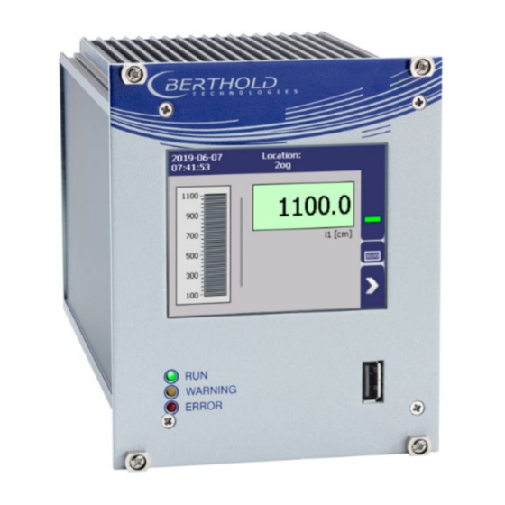
LB 478 MPLM 3 System Description Front/rear view EVU Front view EVU The following control elements are found on the front of the EVU: · LEDs for status display of individual operating states · 3.5'' Touch display · USB port. 3.5'' Touch display RUN LED WARNING LED... - Page 20 3 System Description LB 478 MPLM Status displays of the master EVU The LEDs (Fig. 3, items 2-4) below the touch display show the current operating status of the master EVU. Display LED Description RUN This LED lights up green if the device is in operation and fault-free.
- Page 21 LB 478 MPLM 3 System Description Rear view EVU The following connections are located on the back of the EVU: · Master/slave connector, 4-pin · RJ45 socket for Ethernet · 32-pin plug connector Master/slave 4-pin connector RJ45 socket for Ethernet 32-pin plug connector Fig.
-
Page 22: Type Plate
3 System Description LB 478 MPLM Type plate Application Master (M) or extension module (E) Approval explosion protection (0 = no permissible temperature range for explosion approval) operation (ambient temperature) Power supply Power specifications (1 = 24 V DC; 2=100…240 V AC -10 +10%) Fig. -
Page 23: Installation
The applicable national regulations of the country of use have to be observed! Repair and maintenance on the devices may only be performed by experts (see chapter 2.3). In case of doubt, the complete device must be returned to Berthold for repair. -
Page 24: Installation In The 19" Subrack
4 Installation LB 478 MPLM Installation in the 19" subrack The 19" subrack can be equipped differently, depending on requirements. The rear clamp blocks (Fig. 6, item 3) are used for the electrical connection. NOTICE The 19" subrack may only be installed in a dry environment. The subrack is installed in a 19"... -
Page 25: Installation With Clamp Blocks
LB 478 MPLM 4 Installation Installation with clamp blocks j DANGER Danger to life from electric shock! Installation/maintenance may only be carried out if the device has been de- energised. Test of absence of harmful voltages when the front side is open. In case of an electric shock, carry out first aid measures and immediately call an emer- gency service. - Page 26 4 Installation LB 478 MPLM 56925-8BA2 Rev.00, 07/2019...
-
Page 27: Electric Installation
LB 478 MPLM 5 Electric Installation Electric Installation General Instructions j DANGER Danger to life from electric shock! The installation may only be carried out by a qualified electrician. Please adhere to the relevant safety regulations. Open the housing only in a dry environment and for installation, mainte- nance and servicing. -
Page 28: Circuit Breaker
(there and back) of 40 ohms. For standard cables from Berthold (Id. no. 32024), this results in a cable length of 1000m, from the evaluation unit to the detector. For intrinsically safe systems, the maximum permissible induct- ance and capacitance of the cable should be considered to the max. -
Page 29: Cable Glands And Blanking Elements
Cable bushings and blanking elements must comply with the applicable IP pro- tection class and with the requirements for the operational environment. We recommend ordering missing cable glands, blanking elements or adapters from Berthold. Protective earth and equipotential bonding The protective earth conductor has to be connected to the terminals marked with "PE". -
Page 30: Wiring Diagram
5 Electric Installation LB 478 MPLM Wiring diagram The detectors LB 480 are connected to the evaluation unit via the RS485 terminals. Connect the communication lines according to assignment to clamp blocks (Fig. 7). Observe the circuit diagrams of the EVU in the document “Technical Information”. NOTICE Observe the circuit diagrams of the control unit and the detectors for connect- ing. -
Page 31: Electrical Connection In The 19" Subrack
LB 478 MPLM 5 Electric Installation Electrical connection in the 19″ subrack The electrical connections are made via clamp blocks. These clamp blocks are al- ready installed in the 19" subracks and are also available as an optional accessory. j DANGER Danger to life from electric shock! The installation may only be carried out by a qualified electrician. - Page 32 5 Electric Installation LB 478 MPLM Plug the network plug into the RJ45 socket (Fig. 8, item 3) (optional). Check the correct connection of the PE conductor (Fig. 8, item 4). NOTICE Note the specification relating to Protective earth and equipotential bonding in chapter 5.1.4 .
-
Page 33: Switching Current Output
LB 478 MPLM 5 Electric Installation Switching current output Switching between "SOURCE" (active) and "SINK" (passive) is possible using the slide switch on the I/O board. Factory setting EVU is delivered in "SOURCE" mode. j DANGER Danger to life from electric shock! The switching may only be carried out by a qualified electrician. - Page 34 5 Electric Installation LB 478 MPLM 56925-8BA2 Rev.00, 07/2019...
-
Page 35: Operation Of The Software
LB 478 MPLM 6 Operation of the Software Operation of the Software System start Fig. 10 Start screens with display of the software version System start with invalid application software A different menu structure is present in this mode. Fig. 11 Start screen (Invalid application software) IMPORTANT The communication between the sensor and EVU is limited to 1200 baud. -
Page 36: Evu Standard Display
6 Operation of the Software LB 478 MPLM EVU standard display IMPORTANT Changing the language of the user interface is changed in menu Device Setup | Setup | System | Interfaces | Languages. Level scale Button “Menu” Date and Time Button “Diagram”, “Monotonized densities”... -
Page 37: Navigation
LB 478 MPLM 6 Operation of the Software Navigation Home (standard display) Display of monotonized densities Diagram display One menu level back Data display One menu level forward Fig. 13 Icons for navigation Diagram display Clicking the symbol (Fig. 12, item 6) changes the view to the display monotonized of densities (Fig. -
Page 38: Event Reports
6 Operation of the Software LB 478 MPLM Event Reports Events are displayed in the standard display and in the submenus as a symbol. All events are displayed on the main screen. A specific “D” (for detector) indicates that a detector has an event, the prefix “M” (for measuring unit) indicates that there is an event in the LB 478 transmitter. -
Page 39: Input Field
LB 478 MPLM 6 Operation of the Software Input field NOTICE The input field appears by clicking on the blue display panels. Input line Input key Shift key for numbers Delete key Shift to upper case characters Number field Escape key Home (item1) key Keypad End key... - Page 40 6 Operation of the Software LB 478 MPLM 56925-8BA2 Rev.00, 07/2019...
-
Page 41: Main Menu Device Setup
LB 478 MPLM 7 Main Menu Device Setup Main Menu Device Setup Menu structure master EVU Main Menu - Device Setup Chap. 7.1 Identfification Location Device Information Chap. 7.2 Access Chap. 7.3 Setup System Interface Densities Sensors Densities Overview Outputs Detector Densities Date / Time... -
Page 42: Menu Identification
7 Main Menu Device Setup LB 478 MPLM Fig. 18 Menu “Main Menu”, “Device Setup” Menu Identification Device Setup | Identification You can make the following settings and read information in the Identification menu: · Display and change the location name ·... -
Page 43: Location
LB 478 MPLM 7 Main Menu Device Setup Location Device Setup | Identification | Location The location of the evaluation unit is displayed in the “Location” menu. The name can only be edited (7.2 Menu Access) in the access level "Standard". The Location is displayed on the EVU standard display (Fig. -
Page 44: Device Information
Carry out a backup of the measuring channel settings before resetting and the update of the EVU (10.3 Data backup). The secured settings should then be imported after the successful software update. The current software versions can be downloaded from the Berthold website (www.berthold.com). 56925-8BA2 Rev.00, 07/2019... - Page 45 The update is performed. Measurement is interrupted. Click the Button <Restart> to reboot the EVU. NOTICE Berthold recommends calibrating the current outputs whenever a module has been installed/replaced or if a software update has been carried out. 56925-8BA2 Rev.00, 07/2019...
-
Page 46: Menu Access
7 Main Menu Device Setup LB 478 MPLM Menu Access Device Setup | Access You can set the user rights via the user levels and assign passwords in the submenu Access. After assigning a password the system is protected against unauthorized manipulation of the parameters. - Page 47 User Level Admin This access level is only intended for the system management by Berthold. NOTICE Incorrect measurement and calibration parameters can be set through unau- thorised inputs. These can possibly lead to production losses and damage in the system.
-
Page 48: Menu Setup
7 Main Menu Device Setup LB 478 MPLM Menu Setup Device Setup | Setup Fig. 24 Menu “Setup“ System (Date / Time, Interfaces, Units, Network, Reset, Repair Det. Software) Device Setup | Setup | System Fig. 25 Submenu "System" 56925-8BA2 Rev.00, 07/2019... - Page 49 LB 478 MPLM 7 Main Menu Device Setup Set Date and Time Device Setup | Setup | System | Date / Time IMPORTANT The date and time must always be set correctly so that all records (log files) have the correct metadata. The correct date is also indispensable for the decay compensation.
- Page 50 7 Main Menu Device Setup LB 478 MPLM Interfaces Device setup | Setup | System | Interfaces You can adjust the following settings in the submenu “Interfaces” (Fig. 27): · Local Display o Brightness / Touch o Input / Output ·...
- Page 51 LB 478 MPLM 7 Main Menu Device Setup Brightness / Timeout Device Setup | Setup | System | interfaces | Local Display | Brightness / Timeout Input field “Time out” Input field “Dimming” Input field Display switch off “Time out” Input field Display switch off “Dimming”...
- Page 52 7 Main Menu Device Setup LB 478 MPLM Input / Touch Device Setup | Setup | System | Interfaces | Local Display | Input / Touch Button <Calibrate touchscreen> Fig. 30 Input/ Touch Calibrate touch screen The calibration may only be carried out with direct skin contact. Take gloves or any other protective equipment off your hands.
- Page 53 LB 478 MPLM 7 Main Menu Device Setup Language Device Setup | Setup | System | Interfaces | Language 1 Selection arrow Fig. 32 Language Change system language Click on the selection arrow (Fig. 32, item 1) and select a language. A message window “Restart”...
- Page 54 7 Main Menu Device Setup LB 478 MPLM CE Remote Control Device Setup | Setup | System | interfaces | Remote Control By activating (Fig. 33, item 1) the CE Remote Control, the unit can be operated via the network connection. The software of the remote control (RC software) is stored on the device and can be copied to a USB storage device.
- Page 55 LB 478 MPLM 7 Main Menu Device Setup Units Device Setup | Setup | System | Units Clicking on the individual selection arrow lists the available units for the measuring value. The selected unit is used in the output settings and is shown in the standard display.
- Page 56 7 Main Menu Device Setup LB 478 MPLM Network Device Setup | Setup | System | Network In the Network settings, you can make changes to the network settings. The infor- mation can only be edited in the access level "Standard" (see chap. 7.2 Menu Access).
- Page 57 LB 478 MPLM 7 Main Menu Device Setup Remote Control Software If the EVU is connected to a network at the RJ45 socket (Fig. 3, item 2), the EVU can be operated via a computer. The software can be loaded onto a USB storage device (see Chapter “CE Remote Control”).
- Page 58 7 Main Menu Device Setup LB 478 MPLM Reset Device (evaluation unit) Device Setup | Setup | System | Reset Device The evaluation unit can be restarted and reset to factory settings in the window “Reset Device”. Button Reboot Button Factory settings Window “Warning: Reboot”...
- Page 59 Device Setup | Setup | System | Repair Detector Software In the window "Repair Detector Software" detectors can be repaired and updated. The current software versions for the detectors can be downloaded from the berthold website (www.berthold.com). Description Update / Repair Process "Search for Detectors"...
-
Page 60: Sensors (Only Master Evu)
7 Main Menu Device Setup LB 478 MPLM Sensors (only master EVU) Device Setup | Setup | Sensors All settings of the sensors are carried out via the master EVU. Fig. 39 Menu "Sensors"(only Master EVU) 56925-8BA2 Rev.00, 07/2019... - Page 61 LB 478 MPLM 7 Main Menu Device Setup Detector configuration Device Setup | Setup | Sensors | Detector configuration In the window “Detector configuration” the detectors for the measuring system are added and configured. By clicking the button <Edit> (Fig. 40, item 2) the device ID, the position and description can be changed.
-
Page 62: Interphase Densities (Only Master Evu)
7 Main Menu Device Setup LB 478 MPLM Interphase Densities (only master EVU) An interphase denotes the layer with the respective density. In this menu the in- terphases are defined and a density is assigned to each interphase. The entered density should be the upper limit value of the density for this interphase. -
Page 63: Outputs
LB 478 MPLM 7 Main Menu Device Setup Outputs Device Setup | Setup | Outputs You can make the following settings and read information in the window “Out- puts”: · Analog Output (AO) o AO Mapping o AO monitoring o Failure mode o Current limits o Calibrate ·... - Page 64 7 Main Menu Device Setup LB 478 MPLM 7.3.5.1 Analog Output (AO) AO Mapping (Master EVU) Device Setup | Setup | Outputs | Analog Output (AO) | AO Mapping An Interface can be assigned to the analog output of the master EVU in the win- dow “AO Mapping”.
- Page 65 LB 478 MPLM 7 Main Menu Device Setup AO Failure Mode Device Setup | Setup | Output | Analog Output (AO) | AO Failure Mode The alarm function is set when an error is detected at the current output in the window “Error mode”.
- Page 66 7 Main Menu Device Setup LB 478 MPLM AO Limits Device Setup | Setup | Output | Analog Output (AO) | AO Limits By clicking on the input fields (Fig. 48, item 1, item 2), the values [mA] for the lower and upper current limit can be set.
- Page 67 For calibration of the current output, an ammeter (not included in the scope of delivery) is required, which is connected to the current output. NOTICE Berthold recommends calibrating the current outputs whenever a module has been installed/replaced or if a software update has been carried out. Execution with connection board...
- Page 68 7 Main Menu Device Setup LB 478 MPLM Perform calibration j DANGER Danger to life from electric shock! The repair may only be carried out by a qualified electrician. Please adhere to the relevant safety regulations. During servicing on the hardware as well as during wiring of the detector, the measuring system, connected relay contacts and all inputs and outputs must be de-energised.
- Page 69 LB 478 MPLM 7 Main Menu Device Setup 7.3.5.2 Additional Outputs (only master EVU) Fig. 50 Menu "Additional Outputs“ Already configured outputs are displayed, otherwise only the menu "Configura- tion" is displayed. Configuration Device Setup | Setup | Outputs | Analogue Output (AO) | Additional Outputs | Con- figuration In this menu further outputs of extension modules are added.
- Page 70 7 Main Menu Device Setup LB 478 MPLM AO Mapping (additional outputs) Device Setup | Setup | Outputs | Analog Output (AO) | Out # AO Mapping An Interface can be assigned to an analogue output of the extension module in the window “AO Mapping”.
-
Page 71: Menu Backup/Restore
LB 478 MPLM 7 Main Menu Device Setup Menu Backup/Restore Device Settings | Backup/Restore You can make a backup copy of the configuration data, and perform a recovery in the submenu “Backup/Restore”. Fig. 54 Menu „Backup/Restore“ Backup Device Settings | Backup/Restore | Backup Button <Backup>... - Page 72 7 Main Menu Device Setup LB 478 MPLM The message “Error free” (Fig. 55, item 3) appears in the field “Backup data” for error-free backup files. Click the button <Edit>, enter a description, and confirm with the Enter key. Click on the button <Save>. The backup files are copied to the USB storage device.
-
Page 73: Restore
LB 478 MPLM 7 Main Menu Device Setup Restore Device settings | Backup/Restore | Restore Button < “previous” Number of recovery files on the USB storage device Button > “next” Button <Restore> Recording date of the backup file Time of backup file recording Information about the backup data (error / error free) Confirmation window Fig. - Page 74 7 Main Menu Device Setup LB 478 MPLM 56925-8BA2 Rev.00, 07/2019...
-
Page 75: Main Menu Diagnostics
LB 478 MPLM 8 Main Menu Diagnostics Main Menu Diagnostics Main Menu | Diagnostics Data Log Export Service Data Change Log Transmitter Transmitter (only master EVU) (only master EVU) Temperature Events Transmitter Event Log Transm. Event Overview Fig. 57 Menu “Diagnostics“ Transmitter Temperature Diagnostics | Transmitter Temperature Temperature values from the evaluation unit (processor) are displayed in the menu... -
Page 76: Transmitter Events
8 Main Menu Diagnostics LB 478 MPLM Transmitter Events Diagnostics | Transm. Events Fig. 59 Menuu „Transm. Events“ Information Events of the respective detector can be seen at Device Setup | Setup | Sensors | [NAME OF DETECTOR] | Detector Service. Trasnmitter Event Log Diagnostics | Transmitter Events | Transmitter Event Log The last 25 events of the detector are displayed in the window “Event Log”. - Page 77 LB 478 MPLM 8 Main Menu Diagnostics Display Event Description Button <?> Button <Clear event log> Highlighted event Event no. Event title Event description Button <Close> Fig. 61 display an event log Click on a line in the list (Fig. 61, item 3). Click on <?>...
-
Page 78: Transm. Event Overview
8 Main Menu Diagnostics LB 478 MPLM Transm. Event Overview Diagnostics | Transm. Events | Transm. Event Overview All events that can be logged are chronologically presented in tabular form in the window “Event overview”. Activate the check box “Non-zero Counter only” (Fig. 62, item 5) in order to display events that have occurred. -
Page 79: Change Log
LB 478 MPLM 8 Main Menu Diagnostics Change Log Diagnostics | Change Log You can track changes that were performed on the device in the window “Change log”. Time of the change Short info of the change Value 1 Fig. 63 Change Log (Transmitter) 56925-8BA2 Rev.00, 07/2019... -
Page 80: Data Log (Only Master Evu)
8 Main Menu Diagnostics LB 478 MPLM Data Log (only master EVU) Diagnostics | Data Log You can set the log interval as well as delete and export the log data in the sub- menu “Data log”. IMPORTANT The data cannot be viewed on the EVU Display or via Ethernet. The data must be exported to a USB storage device to view it on a PC. - Page 81 LB 478 MPLM 8 Main Menu Diagnostics Export log data Click on the button <Stop> (Fig. 64, item 2) to stop the data log process. Connect a USB storage device to the device (Fig. 3, item 5). Click on the button <Export>...
-
Page 82: Export Service Data (Only Master Evu)
8 Main Menu Diagnostics LB 478 MPLM Export service data (only master EVU) Diagnostics | Export Service Data < > Button Export service data Process window Confirmation message Fig. 66 Export Service Data Connect a USB storage device to the device (Fig. item 5). -
Page 83: Troubleshooting
LB 478 MPLM 9 Troubleshooting Troubleshooting Error Search Problem Cause Measure Master unit: Screen black; LEDs Check power supply and EVU does not work are not illuminated fuses Extension module: Extension module not Check cabling, contact so- LEDs are not illuminated clamped properly ckets Check Device ID in the... -
Page 84: Error Codes Of The Evaluation Unit
WD Reboot event occurs repeatedly. Check, if mas- sive electromagnetic interferences have caused this event. Watchdog malfunction. Contact M105 WD Failure Berthold service, if this event occurs re- peatedly. Watchdog is inactive. Activate Watch- M106 WD Off 56925-8BA2 Rev.00, 07/2019... - Page 85 Software Reboot The device was restarted by user input. Failure of the external real time clock. M115 Extern RTC malfunction Contact Berthold service, if this event occurs repeatedly. The date could not be verified at M116 Corrupt Date startup. Check date and time and set if necessary.
-
Page 86: Application
Communication to at least one detector interrupted. Check detector connection. D502 Detector comm error Contact Berthold service, if this event oc- curs repeatedly. At least one detector signals "failure". D503 Detector failure Check detector events. -
Page 87: Rs 458 Interface
D602 Detector comm error connection. Contact Berthold service, if this event occurs repeatedly. Internal software failure. Restart the de- D699 Internal program err vice. Contact Berthold service, if this event occurs repeatedly. Process Connection Code Message NAMUR107 Help Text Deviation of analog output value from feeback value is too high. - Page 88 9 Troubleshooting LB 478 MPLM 56925-8BA2 Rev.00, 07/2019...
-
Page 89: Maintenance And Repair
Repair and servicing on the EVU may only be carried out by experts. In case of doubt, the complete EVU is to be sent to Berthold. NOTICE Repair on electronic circuits on the circuit boards of a field device may only be carried out in the manufacturer's factory. -
Page 90: Replacing Of Fuses
10 Maintenance and Repair LB 478 MPLM 10.1 Replacing of Fuses j DANGER Danger to life from electric shock! Replacing of fuses may only be carried out by a qualified electrician. Please adhere to the relevant safety regulations. Installation/maintenance may only be carried out if the device has been de-energised. - Page 91 LB 478 MPLM 10 Maintenance and Repair Remove the protective covering of the fuse (Fig. 67, item 4) Remove the fuse (Fig. 67, item 5, item 7). Insert the new fuses and attach the protective covering again. Carefully slide the circuit board into the housing. Screw the front panel to the housing with the four screws (Fig.
-
Page 92: Cleaning
10 Maintenance and Repair LB 478 MPLM 10.2 Cleaning The display is designed for maintenance-free operation. Make sure you keep the touch screen clean. Use a cleaning cloth dampened with a cleaning agent to clean the equipment. Only use water with a little liquid soap or a screen cleaning foam. NOTICE Unintentional reaction! When cleaning the touchscreen, touching keys can trigger an unintentional re-... -
Page 93: Data Backup
LB 478 MPLM 10 Maintenance and Repair 10.3 Data backup Activate the data log (see chapter 8.4) so that all data are recorded. Perform a log data and service data backup at regular intervals. Export service data Diagnostics | Export Service Data Four .txt files are copied to the USB drive when exporting service data: ·... - Page 94 10 Maintenance and Repair LB 478 MPLM 56925-8BA2 Rev.00, 07/2019...
-
Page 95: Decommissioning
LB 478 MPLM 11 Decommissioning Decommissioning j DANGER Danger to life from electric shock! Decommissioning may only be carried out by qualified electricians. Please adhere to the relevant safety regulations. Decommissioning may only be carried out if the device has been de-ener- gised. -
Page 96: Disposal Of Measurement System
11 Decommissioning LB 478 MPLM 11.2 Disposal of Measurement System j CAUTION Toxic! The product contains electronic components containing toxic substances that are harmful to health. Disposal is to be carried out in accordance with the disposal regulations via a disposal expert. If the device is to be decommissioned, have it disposed of according to legal regu- lations (e.g. -
Page 97: Appendix
LB 478 MPLM 12 Appendix Appendix 12.1 Commissioning Guide This guide is intended to support and document the installation and commission- ing of Multiphase Level Measurement (MPLM) systems. The document is divided into the following sections: · Underlying data · Implementation on site ·... -
Page 98: Underlying Data
The data required for an installation of the MPLM system are listed here. Some data have already been defined in Berthold's factory or clarified with the customer in advance. All information must be agreed with the customer or the responsible process engineer. - Page 99 LB 478 MPLM 12 Appendix Interfaces Interface Density limit Expected position value in ______ ranges in ______ Total Level (Gas Density) Evaluation Unit Device-ID Master Location Extension Module Device-ID Extension Description The selected units must be consistent with the settings of the evaluation unit! 56925-8BA2 Rev.00, 07/2019...
-
Page 100: Implementation On Site
12 Appendix LB 478 MPLM Implementation on site At this point, the steps to be carried out on site are listed. A detailed description of the installation, electrical installation, etc. can be found in the respective oper- ating instructions. Safety instructions must be observed! Detector Positioning In most cases, the detectors are installed by the customer. - Page 101 LB 478 MPLM 12 Appendix Are all additional outputs created? An analog output must be created for each additional evaluation unit (extension module). Fig. 73 Example extension module (outputs) configuration Scaling of analog outputs according to the specifications for position ranges (see Table “Interfaces”...
- Page 102 12 Appendix LB 478 MPLM Calibration of detectors NOTE Each detector must be calibrated individually! As part of the calibration procedure, the container must be emptied or filled, time must be allowed for this. For the detectors of a MPLM system, a two-point calibration is performed, i.e. first the calibration of all detectors is carried out at density A and then at density B.
-
Page 103: Setup Protocol Lb 478
LB 478 MPLM 12 Appendix 12.2 Setup Protocol LB 478 The commissioning is carried out by means of setup protocols for the evaluation units and the detectors. Note: A separate protocol must be completed for each detector! General data Date Measuring point Number of dectors LB480... - Page 104 12 Appendix LB 478 MPLM Setup Protocol (Continued) Parameters Password Language CE Remote Control enabled Network DHCP active IP Adress Subnet Ggateway DNS-Server MAC Adress Process Value Range min. Value 0 / 4,00 mA (Master) max. Value 20,00 mA Process Value Range min.
-
Page 105: Setup Protocol Lb480 Mplm
LB 478 MPLM 12 Appendix 12.3 Setup Protocol LB480 MPLM Measuring point Date Isotope Detector Position (Height) Detector Path Parameters Unit Standard Setup Device Config u Meas Parameter u Meas Data Background Device Config u Meas Parameter u Meas Data u Meas Table Point Density Rate... - Page 106 12 Appendix LB 478 MPLM Device Config u Setup u Sensor Configuration u Sensor Settings Detector Code 0 ... 50 HV Mode AUTO / MANUAL HV Live HV Average HV Manual HV Default Device Config u Setup u Signal Condition u Signal Parameter Time Const NORMAL / Error Handling...
- Page 107 LB 478 MPLM 12 Appendix Device Config u Setup u I/O Setup u Current Output Current Loop DISABLED ENABLED Montitoring ENABLED HIGH LOW HOLD Loop Alarm Type LAST VALUE HIGH VALUE Error Current Va- 22,00 Current Lower Li- 3,80 Current Upper Li- 20,50 56925-8BA2 Rev.00, 07/2019...
- Page 108 Modifications due to technical advancement reserved. © BERTHOLD TECHNOLOGIES GmbH & Co. KG Language: English Printed in Germany 07/2019 Rev. no.: 00 BERTHOLD TECHNOLOGIES GmbH & Co. KG Calmbacher Str. 22 75323 Bad Wildbad Germany www.Berthold.com Id.-No. 56925-8BA2...
- Page 109 Unité d'évaluation Détecteurs LB 47x LB 4700 Informations sur la sécurité 56925BA59 Rev. No.: 03, 05/2019...
- Page 110 1 A propos de ce manuel d’utilisation A propos de ce manuel d’utilisation Avertissement Les avertissements sont identifiés comme suit : Signalement Source et conséquence Explication si requise Prévention En cas de danger · Symboles d’alerte : (triangle d’alerte) attire l’attention sur le risque. ·...
- Page 111 1 A propos de ce manuel d’utilisation RECOMMANDATION Si cette information n’est pas appliquée, un dysfonctionnement et/ou un dégât matériel peuvent apparaître. IMPORTANT Les sections identifiées avec ce symbole signalent des informations importantes du produit ou de son fonctionnement. Fournit des conseils sur l’application ou d’autres informations utiles. 56925BA59 Rev.
- Page 112 1 A propos de ce manuel d’utilisation 1.8.2 Symboles utilisés sur l’appareil Lire le manuel d’utilisation Veuillez suivre les instructions dans ce manuel d’utilisation. Décharge électrostatique Veuillez noter les instructions de manipulation. Composants sensibles aux décharges électrostatiques. Veuillez suivre les instructions de ce manuel d’utilisation.
- Page 113 Conformité La société BERTHOLD déclare par la présente, sous son entière responsabilité, que la conception de ce produit mis sur le marché par BERTHOLD est conforme aux directives EU indiquées dans la déclaration de conformité originale. Cette disposition devient nulle en cas de modifications non autorisées par Berthold ou dans le cas d’une utilisation impropre.
- Page 114 ! · Suivre les instructions de sécurité mentionnées ! faire · Effectuer les opérations de maintenance prescrites ou les réaliser pour vous ! · Utiliser uniquement les accessoires et pièces de rechange BERTHOLD. 56925BA59 Rev. 03, 05/2019...
- Page 115 · Manoeuvre inappropriée ou oubli des équipements de sécurité présents. BERTHOLD assume la responsabilité de la garantie seulement dans le cadre de ses spécifications publiées. Si le produit est utilisé dans des conditions autres que celles décrites dans le présent manuel, la sécurité...
- Page 116 Les personnes autorisées sont celles désignées pour les tâches correspondantes dans le cadre de dispositions réglementaires, ou celles dûment autorisées par BERTHOLD pour des tâches particulières. Lors de la mise en œuvre de matières radioactives, la personne compétente en radioprotection doit être consultée...
- Page 117 2 Sécurité Les obligations de l'opérateur L’opérateur de ces appareils doit régulièrement former son personnel sur les sujets suivants : · Connaissance et utilisation du manuel d’utilisation et des clauses légales. · Utilisation prévue de l’appareil. · Respect des instructions de sécurité du site et des conditions d’utilisation de l’opérateur.
- Page 118 Sous réserve de modifications dans le cadre du progrès technique. © BERTHOLD TECHNOLOGIES GmbH & Co. KG Sprache: Français Printed in Germany 05/2019 Rev.-Nr.: 03 BERTHOLD TECHNOLOGIES GmbH & Co. KG Calmbacher Str. 22 75323 Bad Wildbad Germany www.Berthold.com Id.-Nr. 56925BA59...
- Page 119 EmulsionSENS Technical Information Technische Information 56925TI1M Rev. No.: 00, 07/2019...
- Page 120 Technical Information - EmulsionSENS Technische Information - EmulsionSENS Evaluation unit Auswerteeinheit 56925TI1M Rev. 00, 07/2019...
- Page 121 Technical Information - EmulsionSENS Technische Information - EmulsionSENS Installation variants 19” subrack Einbauvarianten 19” Baugruppenträger Item Compontens Connection Pos. Komponenten Anschluss 4x EVU 4 Terminal blocks (1 Master, 3 extension modules) 4 Klemmenblöcke 3x EVU, 1x blanking panel 3 Terminal blocks (1 Master, 2 extension modules) 3 Klemmenblöcke 2x EVU, 2x blanking panel...
- Page 122 Technical Information - EmulsionSENS Technische Information - EmulsionSENS Assignment terminal block master EVU Belegung Klemmenblock Master AWE Signal Signal not assigned nicht belegt C - 2 A - 2 not assigned nicht belegt not assigned nicht belegt C - 4 A - 4 not assigned nicht belegt...
- Page 123 Technical Information - EmulsionSENS Technische Information - EmulsionSENS 19" subrack 19” Baugruppenträger Terminal block Terminal board Dimensions in mm Abmessungen in mm Technical Data Technische Daten Dimensions 3HE/84TE/5T, Abmessungen 482x132x172mm (WxHxD) Max. Assembly - 4 Master Max. Bestückung Weight (with circuit board, without modules) 1.4 kg Gewicht (mit Anschlussplatine, ohne Module) Weight terminal block...
- Page 124 Technical Information - EmulsionSENS Technische Information - EmulsionSENS Dimensions in mm Abmessungen in mm Technical Data Technische Daten Dimensions 117/128/172mm (WxHxD) Abmessungen Weight 1200 g Gewicht Operational temperature -20°C … +50°C, not condensing. Avoid direct sunlight. Unobstructed air Betriebstemperatur circulation must be provided to the subrack. -20°C …...
- Page 125 Technical Information - EmulsionSENS Technische Information - EmulsionSENS Connections - USB port for the connection to the USB storage medium - Master/slave connection (4-pin) and plug - RJ45 connection for Ethernet (on back wall) - 32-pin plug connector according to DIN 19465 Series C Anschlüsse - USB-Port zum Anschluss von USB-Speichermedium - Master/Slave Buchse (4-polig) und Stecker...
- Page 126 Technical Information - EmulsionSENS Technische Information - EmulsionSENS Interfaces Schnittstellen Current 4-20mA internally switched from power source to sink current (according to NAMUR output recommendation NE 006 and NE 043). Continuous short circuit proof and isolated (500 V). Internal resistance about 105 ohms max. Burden when operating as a power source: 850 ohm.
- Page 127 Technical Information - EmulsionSENS Technische Information - EmulsionSENS USB port 1 x USB 2.0 Type A (Host) via front plate to the connection of an ext. mouse, keyboard or storage medium Uout = 5 V, Ioutmax = 0.5 A 1 x USB 2.0 Typ A (Host) über Frontplatte zum Anschluss einer ext. Maus, Tastatur oder Speichermedium Uout = 5 V, Ioutmax = 0,5 A Ethernet...
- Page 128 Technical Information - EmulsionSENS Technische Information - EmulsionSENS Number Key LB 47x Nummernschlüssel LB 47x 3 4 5 4 7 x RID (only LB 470 / nur LB 470) No RID / Kein RID Family / Gerätefamilie -RID Radiation Interference Descrimination DuoXpert Options / Austattungsmerkmale Master...
- Page 129 Technical Information - EmulsionSENS Technische Information - EmulsionSENS Declaration of Conformity Konformitätserklärung 56925TI1M Rev. 00, 07/2019...
- Page 130 Technical Information - EmulsionSENS Technische Information - EmulsionSENS 56925TI1M Rev. 00, 07/2019...
- Page 131 Technical Information - EmulsionSENS Technische Information - EmulsionSENS Certificates Zertifikate NRTL certification US/CAN wall-mounted housing NTRL Zertifikat US/CAN Wandgehäuse 56925TI1M Rev. 00, 07/2019...
- Page 132 Technical Information - EmulsionSENS Technische Information - EmulsionSENS NRTL certification US/CAN wall-mounted housing (continued) NTRL Zertifikat US/CAN Wandgehäuse (Fortsetzung) 56925TI1M Rev. 00, 07/2019...
- Page 133 Technical Information - EmulsionSENS Technische Information - EmulsionSENS NRTL certification US/CAN wall-mounted housing (continued) NTRL Zertifikat US/CAN Wandgehäuse (Fortsetzung) 56925TI1M Rev. 00, 07/2019...
- Page 134 Technical Information - EmulsionSENS Technische Information - EmulsionSENS NRTL certification US/CAN DuoXpert LB 47x NTRL Zertifikat US/CAN DuoXpert LB 47x 56925TI1M Rev. 00, 07/2019...
- Page 135 Technical Information - EmulsionSENS Technische Information - EmulsionSENS NRTL certification US/CAN DuoXpert LB 47x (continued) NTRL Zertifikat US/CAN DuoXpert LB 47x (Fortsetzung) 56925TI1M Rev. 00, 07/2019...
- Page 136 Technical Information - EmulsionSENS Technische Information - EmulsionSENS Parts overview Übersicht Zubehör ID. No. Description Id. Nr. Beschreibung LB 478-01-M MPLMTransmitter (Master, 24 VDC) 68867 LB 478-01-M MPLM-Messgerät (Master, 24 VDC) LB 478-02-M MPLM Transmitter (Master, 100...240 VAC) 68866 LB 478-02-M MPLM-Messgerät (Master, 100...240 VAC) LB 478-01-E Transmitter (Extension, 24 VDC) 68869 LB 478-02-E Messgerät (Erweiterung, 100...240 VAC)
Need help?
Do you have a question about the Duo Xpert LB 478 MPLM and is the answer not in the manual?
Questions and answers