
Related Manuals for Omega SP-006


Summary of Contents for Omega SP-006
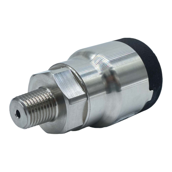
- Page 1 User’ s Gui d e Shop online omega.com e-mail: info@omega.com For latest product manuals: www.omegamanual.info SP-006 Layer N Pressure Monitoring and Control Smart Probe M 5 7 7 9...
- Page 2 Germany 75392 Irlam, Manchester M44 5BD The information contained in this document is believed to be correct, but OMEGA accepts no liability for any errors it contains and reserves the right to alter specifications without notice. M 5 7 7 9...
-
Page 3: Table Of Contents
5.4.2 Sensor Output Mapping ............................. 15 5.4.3 ON/OFF Control Module ............................ 17 5.4.4 Setting an Alarm ..............................18 Appendix: SP-006 Registers........................19 Register Base Addresses ..........................19 Pressure Sensor .............................. 19 6.2.1 Pressure Descriptor ............................19 6.2.1.1 Pressure Sensor Type ..............................19 6.2.1.2... - Page 4 Discrete I/O Interface ............................. 25 6.4.1 DIO Descriptor ..............................25 6.4.1.1 DIO Sensor Type ................................25 6.4.1.2 DIO Data Type/Format ..............................25 6.4.1.3 DIO Input Configuration ..............................26 6.4.1.4 DIO Device Configuration..............................26 6.4.2 DIO IPSO Definition ............................27 6.4.2.1 Sensor Trigger Function ..............................
-
Page 5: Notes Cautions And Warnings
The following labels identify information that is especially important to note: Note: Provides information that is important to successfully set up and use the SP-006. Caution or Warning: Informs about the risk of electrical shock. -
Page 6: Introduction
M12 8-pin connector. See Figure 1. For additional functionality, the Layer N SP-006 features 2 configurable discrete I/O pins which can be used for a myriad of applications including driving relays, physical alarms, or sensing dry contacts like door switches. The SP-006 can also be utilized as an edge controller with autonomous independent decision-making capabilities to generate local alarms or provide control outputs based on sensor inputs. -
Page 7: Specifications
Storage Temperature: -40 to 85°C (-40 to 185°F) less than 95% RH, non-condensing Environmental Rating: IP50 GENERAL Configuration: Configurable via Layer N Smart Interface and SYNC configuration software Software: Compatible with OEG, SYNC, and OMEGA Cloud Figure 3: SP-006 Dimensions and Pressure Ports M 5 7 7 9... -
Page 8: Hardware Setup
Connecting your Layer N Smart Interface The SP-006 requires a Layer N Smart Interface to connect to a computer. Omega offers a variety of Layer N Smart Interfaces such as the wired IF-001 (USB) and IF-002 (Modbus) or the wireless IF-006. Use the M12 8-Pin Connector diagram below to connect the SP-006 to a Layer N Smart Interface. -
Page 9: Sync Configuration
Layer N Smart Probe products are easily configurable through Omega’s SYNC configuration software. Ensure SYNC is running on a Windows OS computer before continuing. Connect the SP-006 to a computer running SYNC through your Layer N Smart Interface to begin. -
Page 10: Input Configuration
The SP-006 provides readings for pressure, temperature, and discrete I/O (DIO). To use these features, click the Inputs configuration tab on SYNC and choose your preferred input mix from the Type dropdown. The SP-006 allows selecting pressure and discrete I/O only or pressure, temperature, and discrete I/O. -
Page 11: Pressure User Calibration
After clicking the Calibration button, the user must follow the onscreen directions to calibrate the device. Figure 8: SYNC pressure user calibration 5.3.2 Temperature The SP-006 Temperature readings may be configured under the advanced scaling options which include Gain and Offset. Figure 9: SYNC interface temperature input 11 | M 5 7 7 9... -
Page 12: Discrete Input/Output (Dio)
5.3.3 Discrete Input/Output (DIO) The Layer N SP-006 features 2 configurable discrete I/O pins DIO_0 and DIO_1. These DIO pins can be used for a myriad of applications including driving relays, physical alarms, or sensing dry contacts like door switches. The user may configure the polarity of the inputs (active HIGH or active LOW) or Disable the DIO to utilize the outputs (ON/OFF, PWM, SERVO). -
Page 13: Advanced Scaling Options
Output Configuration The SP-006 offers two discrete outputs that share circuitry with the discrete inputs. If an output is to be used then the corresponding input pin must be set to Disable. See section 5.3.3 Discrete Input/Output (DIO) for more information. -
Page 14: Device Output Range/Types
An output may be controlled in one of three ways – a scaled mapping to an input, an on/off control from an input setpoint, or as an input alarm. Sections 5.4.2 through 5.4.4 describe these output control methods. 5.4.1 Device Output Range/Types There are three types of output options –... -
Page 15: Servo Output Type
Sensor Output Mapping The SP-006 allows mapping a scaled copy of any of the input values to any of the outputs. To set a mapped output, it must not be associated with any alarm or ON/OFF control module. Two user-defined values, Scaling Minimum and Scaling Maximum, define the sensor range that is mapped to the output. - Page 16 ���������������� ���� ���� ���� �������� ���� ���� ���� �������� − ���� ���� ������������ �������������������� ���� ���� ������������ ���� �������� ���������������������������� = � � × 100% ���������������� ���� ���� ���� �������� ���� ���� ���� �������� − ���������������� ���� ���� ���� ���������������� ���� �������� ����������������������������...
-
Page 17: On/Off Control Module
5.4.3 ON/OFF Control Module To configure an ON/OFF control module on a device, first ensure that the desired output pin is not associated with any input alarms and that it is set as No Mapping in the Output Mapping menu in the Outputs tab. -
Page 18: Setting An Alarm
5.4.4 Setting an Alarm Alarms are set by clicking the icon in SYNC on the desired input signal found in the Input Tab. Figure 21: SYNC alarm configuration interface Configure the Condition that triggers the alarm by selecting an option from the drop-down such as Above, Below, Outside the Range, or Within the Range. -
Page 19: Appendix: Sp-006 Registers
6 Appendix: SP-006 Registers The following Appendix provides the registers and list index for the Layer N SP-006 Pressure monitoring Smart Probe. This information is intended to aid users who will be making configurations and adjustments to their Layer N SP-006 Pressure monitoring Smart Probe through the Command Line Interface or other custom interfaces. -
Page 20: Pressure Data Type/Format
Data Type The 4-bit Data Type field determines the type of data of the specific sensor. 6.2.1.2.2 Factory Calibrate Factory calibration is available for the SP-006 process inputs. Clearing this bit will disable the factory calibration values. 6.2.1.2.3 Writeable The writeable bit is cleared, indicating that the sensor values may not be overwritten. -
Page 21: Pressure Sensor Device Byte
6.2.3 Pressure User Calibration Parameters The SP-006 provides four User Calibration registers that allow setting a 2-point calibration/linearization. The four parameters may only be set while the device is in the User Calibrate mode. When the calibration function is triggered the device will calculate the Gain and Offset used in the linearization process. The calibration process is performed by the following steps: 1) Send Sensor Function Calibrate Mode trigger to set the device to calibration mode. -
Page 22: Ipso Pressure Sensor Definition
Value read by SP-006 (higher value) High Actual (Y2) +/- 100000 Full Scale Actual applied load (higher value) 6.2.4 IPSO Pressure Sensor Definition The SP-006 IPSO pressure definition provides signal range, measured min/max values, IPSO object type information. Offset Name Value Description 0x00... -
Page 23: Max Range
6.3.1 Temperature Descriptor The SP-006 configures the sensors based on the factory device list and user-specified list index. The Sensor Configuration and Sensor Device fields may be written to provide control of the overall function of the channel and the signal types used. -
Page 24: Temperature Configuration Byte
There are no user-accessible parameters for the temperature sensor. 6.3.3 Temperature User Calibration There are no temperature user calibration registers assigned. 6.3.4 IPSO Temperature Sensor Definition The SP-006 IPSO temperature definition provides signal range, measured min/max values, IPSO object type information. Offset Name Value Description... -
Page 25: Sensor Trigger Function
Discrete I/O Interface The SP-006 supports a DIO Interface that provides 2 discrete inputs that are hardwired to the outputs. These may be used to detect the state of external switches (output off) or to monitor the state of the outputs. -
Page 26: Dio Input Configuration
6.4.1.2.2 Factory Calibrate The Factory Calibrate bit is not used for DIO types. 6.4.1.2.3 Writeable This indicates that the sensor value may be overwritten. Not used on DIO inputs. 6.4.1.2.4 Smart Sensor Refer to the Smart Sensor Device Interface documentation. 6.4.1.3 DIO Input Configuration DIO Input Configuration... -
Page 27: Dio Ipso Definition
6.4.2 DIO IPSO Definition The DIO input IPSO definition provides signal range, measured min/max values, IPSO object type information. Offset Name Value Description 0xa8 Sensor Type 3349 Bit Mapped Digital 0xaa Precision Provides reading of xxx 0xac Sensor Trigger Write 0x0001 force reset of min / max 0xb0 Min Measured Minimum reading since the last reset... -
Page 28: Scaling Minimum / Maximum Values
6.5.1 Scaling Minimum / Maximum Values When Input Mapping is used the user may specify the input signal range through the Input Minimum and Input Maximum parameters. There is one pair of registers for each of the 4 possible outputs. Modbus Sensor Name... -
Page 29: Output Configuration
Output Configuration The SP-006 provides two output signals which may be configured for ON/OFF, PWM, or SERVO outputs through the Output Configuration registers. The remaining outputs are assigned as phantom devices which are non-configurable. The highlighted entries show typical default configurations. -
Page 30: Output Type
Servo Rate Name Description PWM signal has constant 100 Hertz frequency (10 msec repetition 100 Hz rate) with 0 – 100 % duty cycle PWM signal has constant 50 Hertz frequency (20 msec repetition 50 Hz rate) with 0 – 100 % duty cycle 6.6.2 Output Type Smart Sensor probes support NULL (0), ON/OFF (1), PWM (2) and SERVO (3) outputs. - Page 31 Department will issue an Authorized Return (AR) number immediately upon phone or written request. Upon examination by OMEGA, if the unit is found to be defective, it will be repaired or replaced at no charge. OMEGA’s WARRANTY does not apply to defects resulting from any action of the purchaser, including but not limited to mishandling, improper interfacing, operation outside of design limits, improper repair, or unauthorized modification.
- Page 32 Where Do I Find Everything I Need for Process Measurement and Control? OMEGA…Of Course! Shop online at omega.com TEMPERATURE M U Thermocouple, RTD & Thermistor Probes, Connectors, Panels & Assemblies M U Wire: Thermocouple, RTD & Thermistor M U Calibrators & Ice Point References M U Recorders, Controllers &...
Need help?
Do you have a question about the SP-006 and is the answer not in the manual?
Questions and answers