
Related Manuals for Omega SP-014


Summary of Contents for Omega SP-014
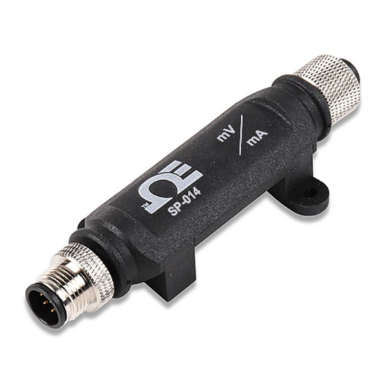
- Page 1 User’s Guide Shop online at omega.com e-mail: info@omega.com For latest product manuals: www.omegamanual.info SP-014 Process Monitoring Smart Probe P a g e...
- Page 2 Tel: (203) 359-1660 Fax: (203) 359-7700 e-mail: info@omega.com The information contained in this document is believed to be correct, but OMEGA accepts no liability for any errors it contains and reserves the right to alter specifications without notice. P a g e...
-
Page 3: Table Of Contents
Connecting to SYNC – Manual ...........................8 4.2.1 Communication Interface ............................. 8 Process Inputs Interface ...........................9 Setting Alarms ..............................10 ON/OFF Control ............................. 10 Appendix: SP-014 Registers........................11 Process Interface ............................11 5.1.1 Process Measurement Types ..........................11 5.1.2 Process Data Type/Format ..........................12 5.1.2.1... - Page 4 5.3.2 Active State................................. 17 5.3.3 Output Drive ............................... 17 5.3.4 Output Type................................ 17 Specifications ............................18 Errata ..............................18 P a g e...
-
Page 5: Notes, Warnings, And Cautions
/ or damage to your equipment. The following labels identify information that is especially important to note: Note: Provides you with information that is important to successfully setup and use the SP-014. Caution or Warning: Tells you about the risk of electrical shock. -
Page 6: Introduction
The Layer N SP-014 features 2 configurable digital I/O pins. These can be used for a myriad of applications including driving relays, physical alarms, or sensing dry contacts like door switches. The SP-014 can also be utilized as an edge controller, with autonomous independent decision-making capabilities to generate local alarms or provide control outputs based on sensor inputs. -
Page 7: Hardware Setup
3 Hardware Setup Connecting your Layer N Smart Interface The SP-014 requires a Layer N Smart Interface to connect to your computer. Use the M12 8-Pin Connector diagram below to connect your SP-014 to your Layer N Smart Interface. Name... -
Page 8: Sync Configuration
SYNC is available to download for free on the OMEGA website. Connecting to SYNC - Automatic Detect Once the SP-014 and Layer N Smart Interface are connected to your computer, SYNC will automatically detect it and begin displaying process readings. -
Page 9: Process Inputs Interface
Once you have completed setting the communication parameters for your device, click Finish. Process Inputs Interface The SP-014 can accept up to three 0-24 mA or 0-1.0 VDC process inputs. To customize your process inputs, follow these steps: Step 1: Click the Inputs configuration tab on SYNC and choose your input type from the Type dropdown. -
Page 10: Setting Alarms
Setting Alarms Alarms are set by clicking the icon in SYNC on the desired input signal found in the Inputs Configuration Tab. Setup the threshold and alarm type in the Condition section and then select which output to turn on in the Action section. The alarm can be set to be latching or non-latching in the Recovery section. -
Page 11: Appendix: Sp-014 Registers
5 Appendix: SP-014 Registers The following Appendix provides the registers and list index for the Layer N SP-014 Process Monitoring Smart Probe. This information is intended to aid users who will be making configurations and adjustments to their Layer N SP-014 Process Monitoring Smart Probe through the Command Line Interface or other custom interfaces. -
Page 12: Process Data Type/Format
5.1.2 Process Data Type/Format The SP-014 supports extended configuration and provides factory calibration. All data values are returned as 32-bit floating point values. Process Input Data Type/Format Smart Factory Writeable Reserved Data Type Sensor Calibrate 0x06 == FLOAT 5.1.2.1 Data Type The 4-bit Data Type field determines the type of data of the specific sensor. -
Page 13: Process Input Sensor Device
5.1.4 Process Input Sensor Device The Sensor Device field determines the signal types for each of the channel bits. CHANNEL 0 SIG 0 .. 2 (Analog Input) Description Single Ended 5.1.5 Process IPSO Definition The IPSO process definition provides signal range, measured min/max values, IPSO object type information. Offset Name Value... -
Page 14: Digital Input / Output Descriptor
Digital Input / Output Descriptor The DIO Interface provides 2 digital inputs which are hardwired to the digital outputs. These may be used to detect the state of external switches (output off) or to monitor the state of the outputs. The DIO Input descriptor is at base addresses 0x0068. -
Page 15: Apply Scaling
5.2.3.2 Apply Scaling If set, the user defined Offset and Gain values will be used to adjust the sensor reading: Result = (Raw Reading * Gain) + Offset 5.2.3.3 Assigned The Assigned bit will always read as 0. Refer to the Smart Sensor Device Interface documentation for further information. -
Page 16: Sensor Trigger Function
5.2.5.1 Sensor Trigger Function The Sensor Trigger function is used to reset the IPSO min/max values as well as controlling the Calibration process. Sensor Trigger Function Reset Min/Max Setting the Reset Min/Max bit to 1 will reset the Min/Max values recorded by the IPSO process. No User Calibration process is supported on the DIO inputs and all bits should be written as 0. -
Page 17: Outputs
5.3.4 Output Type The SP-014 probe supports NULL (0), ON/OFF (1) or PWM (2) outputs. When set to NULL the output signal will be left in a high impedance state. When set to ON/OFF the Rate information has no affect. - Page 18 6 Specifications INPUT POWER Voltage: 2.8 V - 3.3 V DIO DIGITAL INPUTS = 2.2 V inHighThreshold = 0.3 V inLowThreshold = 30 V inMAX DIO DIGITAL OUTPUTS 2x Open Drain 100 mA max = 30 V ANALOG INPUTS Type Range Accuracy Current...
- Page 19 Department will issue an Authorized Return (AR) number immediately upon phone or written request. Upon examination by OMEGA, if the unit is found to be defective, it will be repaired or replaced at no charge. OMEGA’s WARRANTY does not apply to defects resulting from any action of the purchaser, including but not limited to mishandling, improper interfacing, operation outside of design limits, improper repair, or unauthorized modification.
- Page 20 Where Do I Find Everything I Need for Process Measurement and Control? OMEGA…Of Course! Shop online at omega.com TEMPERATURE M U Thermocouple, RTD & Thermistor Probes, Connectors, Panels & Assemblies M U Wire: Thermocouple, RTD & Thermistor M U Calibrators & Ice Point References M U Recorders, Controllers &...
Need help?
Do you have a question about the SP-014 and is the answer not in the manual?
Questions and answers