
Related Manuals for Omega SP-010


Summary of Contents for Omega SP-010
- Page 1 User’s Guide Shop online at omega.com e-mail: info@omega.com For latest product manuals: www.omegamanual.info SP-010 Load Cell Smart Probe P a g e...
- Page 2 Tel: (203) 359-1660 Fax: (203) 359-7700 e-mail: info@omega.com The information contained in this document is believed to be correct, but OMEGA accepts no liability for any errors it contains and reserves the right to alter specifications without notice. P a g e...
-
Page 3: Table Of Contents
Load Cell Interface ............................9 4.3.1 2-Point Calibration ............................. 10 Setting Alarms ..............................10 ON/OFF Control ............................. 11 Appendix: SP-010 Registers........................11 Load Cell Descriptor ............................11 5.1.1 Load Cell Measurement Type ..........................11 5.1.2 Load Cell Input Data Type/Format ........................11 5.1.2.1... - Page 4 5.2.4.1 Sensor Trigger Function ..............................17 5.2.5 DIO Input Circuitry .............................. 17 Outputs ................................. 18 5.3.1 PWM Rate................................18 5.3.2 Active State................................. 18 5.3.3 Output Drive ............................... 18 5.3.4 Output Type................................ 18 Specifications ............................19 P a g e...
-
Page 5: Notes, Warnings, And Cautions
/ or damage to your equipment. The following labels identify information that is especially important to note: Note: Provides you with information that is important to successfully setup and use the SP-010. Caution or Warning: Tells you about the risk of electrical shock. -
Page 6: Introduction
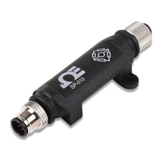
2 Introduction The Layer N SP-010 Load Cell Smart Probe provides an easy way to integrate your bridge devices to the Layer N Ecosystem. The SP-010 accepts 4-wire bridge sensors through its M12 4-pin connector and Layer N Smart Interfaces through its M12 8- pin connector. -
Page 7: Hardware Setup
3 Hardware Setup Connecting your Layer N Smart Interface The SP-010 requires a Layer N Smart Interface to connect to your computer. Use the M12 8-Pin Connector diagram below to connect your inputs and outputs to the SP-010. Name Function... -
Page 8: Sync Configuration
SYNC is available to download for free on the OMEGA website. Connecting to SYNC - Automatic Detect Once the SP-010 and Layer N Smart Interface are connected to your computer, SYNC will automatically detect it and begin displaying readings. Note: If you have successfully connected your SP-010 to SYNC and have readings appearing in SYNC, skip ahead to the section titled Load Cell Interface. -
Page 9: Load Cell Interface
Bridge maximum load Impedance Bridge Impedance TARE (Target) Update this parameter to TARE bridge If the Bridge Impedance is set to 0 the SP-010 will automatically calculate the impedance on the next device reset or power cycle. P a g e... -
Page 10: 2-Point Calibration
4.3.1 2-Point Calibration A 2-point linearization correction may be applied using either known scaling values or reference weights. 2-Point Calibration can be performed as described below: Step 1: From the Load Cell Input interface on SYNC, click Calibrate. Step 2: Place your low reference and click Capture next to Low Reading. -
Page 11: On/Off Control
5 Appendix: SP-010 Registers The following Appendix provides the registers and list index for the SP-010. This information is intended to aid users who will be making configurations and adjustments to their Layer N SP-010 Load Cell Smart Probe through the Command Line Interface or other custom interfaces. -
Page 12: Factory Calibrate
5.1.2.2 Factory Calibrate The Factory Calibrate bit is used during factory calibration. If set, the factory calibration attributes are applied to the sensor reading before the sensor scaling. If clear, not factory calibration attributes are applied. If the sensor does not support factory calibration the Factory Calibrate bit is ignored and will always read as 0. -
Page 13: Load Cell Parameters
The SP-010 provides 3 Sensor Parameters which may be updated based on the specific load cell being used. The Load Cell sensors maps to Sensor 0 of the SP-010. The SP-010 Load Cell Sensor Parameter base address is 0x08c0 (Modbus 0xf460). All values are 32-bit float values. -
Page 14: Load Cell User Calibration Parameters
5.1.7 Load Cell IPSO Definition The Load Cell sensor IPSO definition provides signal range, measured min/max values, IPSO object type information. The Range information is Load Cell Type dependent. The SP-010 Load Cell IPSO definition is at base address 0x08a8. Offset... -
Page 15: Sensor Trigger Function
5.1.7.1 Sensor Trigger Function The Sensor Trigger function is used to reset the IPSO min/max values as well as control the Calibration process. Sensor Trigger Function Reset Min/Max Calibration Calibration Calibration Capture Capture Calibration Reset Status Mode High Start The Calibration mode is entered by writing a 1 to the Calibration Mode bit. While in the calibration mode the calibration registers may be accessed, the Capture High/Low may be used to capture real time values and the Calibration Start may be set. -
Page 16: Sensor Writeable
5.2.1.5 Sensor Writeable If the Sensor Writeable bit is set the sensor value may be overwritten with a preset value. This capability is useful in sensors such as up/down counters, where a preset, or possibly a zero value must be written to the sensor value. 5.2.1.6 Smart Sensor Refer to the Smart Sensor Device Interface documentation. -
Page 17: Sensor Trigger Function
5.2.4.1 Sensor Trigger Function The Sensor Trigger function is used to reset the IPSO min/max values. Sensor Trigger Function Reset Min/Max 5.2.5 DIO Input Circuitry The DIO input circuitry shares the output circuitry. The internal processor drives the Output Control signal to turn on the output driver which will force the output LOW. -
Page 18: Outputs
5.3.4 Output Type The SP-010 probe supports NULL (0), ON/OFF (1) or PWM (2) outputs. When set to NULL the output signal will be left in a high impedance state. When set to ON/OFF the Rate information has no affect. -
Page 19: Specifications
6 Specifications INPUT POWER Voltage: 2.8 V - 3.3 V DIO DIGITAL INPUTS = 2.2 V inHighThreshold = 0.3 V inLowThreshold = 30 V inMAX DIO DIGITAL OUTPUTS 2x Open Drain 100 mA max = 30 V ACCURACY Linearity Error: ±0.03% FSO @25°C Thermal Error: ±0.005% FSO/C ENVIRONMENTAL Operating Temperature: -40 to 85°C (-40 to 185°F) - Page 20 Department will issue an Authorized Return (AR) number immediately upon phone or written request. Upon examination by OMEGA, if the unit is found to be defective, it will be repaired or replaced at no charge. OMEGA’s WARRANTY does not apply to defects resulting from any action of the purchaser, including but not limited to mishandling, improper interfacing, operation outside of design limits, improper repair, or unauthorized modification.
- Page 21 Where Do I Find Everything I Need for Process Measurement and Control? OMEGA…Of Course! Shop online at omega.com TEMPERATURE M U Thermocouple, RTD & Thermistor Probes, Connectors, Panels & Assemblies M U Wire: Thermocouple, RTD & Thermistor M U Calibrators & Ice Point References M U Recorders, Controllers &...
Need help?
Do you have a question about the SP-010 and is the answer not in the manual?
Questions and answers