
Related Manuals for Omega SP-013


Summary of Contents for Omega SP-013
- Page 1 User’ s Gui d e Shop online omega.com e-mail: info@omega.com For latest product manuals: www.omega.com/en- us/pdf-manuals SP-013 Layer N Digital Pulse Smart Probe...
- Page 2 Irlam Manchester M44 5BD United Kingdom The information contained in this document is believed to be correct, but OMEGA accepts no liability for any errors it contains and reserves the right to alter specifications without notice. M 5 7 5 1...
-
Page 3: Table Of Contents
5.4.4 Setting an Alarm ..............................25 Pairing a Sensing Device to a Layer N Gateway ..................26 Wireless Pairing ..............................26 Wired Pairing ..............................26 Appendix: SP-013 Registers ........................27 Digital Descriptor ............................27 7.1.1 Digital Descriptor .............................. 27 7.1.1.1 Digital Measurement Types............................28 7.1.1.2... - Page 4 7.2.3 Process Sensor Parameters ..........................32 7.2.4 Process IPSO Definition ............................. 32 7.2.4.1 Process Resolution ..............................32 7.2.4.2 Process Sensor Trigger Function ..........................32 DIO Interface ..............................33 7.3.1 DIO Descriptor ..............................33 7.3.1.1 DIO Sensor Type ................................33 7.3.1.2 DIO Data Type/Format ..............................33 7.3.1.3 DIO Input Configuration ..............................
-
Page 5: Notes, Warnings, And Cautions
The following labels identify information that is especially important to note: Note: Provides information that is important to successfully set up and use the SP-013. Caution or Warning: Informs about the risk of electrical shock. -
Page 6: Introduction
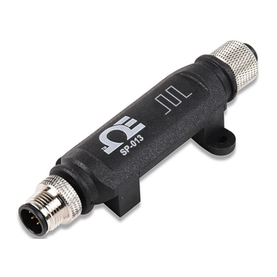
Introduction The Layer N SP-013 Digital Interface Smart Probe provides an easy way to integrate digital pulse inputs into the Layer N Ecosystem. The SP-013 accepts digital pulse inputs through its M12 5-pin connector and Layer N Smart Interfaces through its M12 8-pin connector. The optional M12.8-T-SPLIT Sensor Splitter can be used to access the Discrete I/O pins on the M12 8-pin connector. -
Page 7: Specifications
Specifications INPUT POWER Voltage: 2.8 V - 3.3 V DIGITAL INPUT SIGNALS ON: 1.0 V OFF: 0.7 V Internal Pull Up/Down: 1.5k to 3.0 V Comparator (PULSE) Input: 100 mV, 500 mV, 1.0 V , 2.0 V Type Range Operating Conditions Accuracy Frequency (Rate) 0.01 Hz to 100 Hz... -
Page 8: Hardware Setup
Digital Input Wiring Diagram The Layer N SP-013 accepts digital pulse inputs through its M12 5-Pin connector and a single process input in the mixed input mode. Users connecting wires directly to the SP-013 may refer to the wiring diagram provided below:... -
Page 9: Sync Configuration
SYNC Configuration Layer N Smart Probe products are easily configured through Omega’s free SYNC configuration software. Ensure SYNC is running on a Windows OS computer before continuing. Connect the SP-013 to the computer using your Layer N Smart Interface to begin. - Page 10 • Device Address: If your Smart Interface is part of a network, enter the Network Address here. The default network address is 1 for most devices. Please refer to the manual of your Smart Interface for more information. Note: The default Device Address is 1. •...
-
Page 11: Input Configuration
Input Configuration In Digital Inputs mode, the SP-013 accepts digital pulse inputs and may be configured to monitor the on/off state of the input signals, the pulse rate or pulse duty cycle of the primary input, the up/down count of the primary input, or the pulse delay between two signals. -
Page 12: Pulse Measurements
Digital Input Binary DIN_0 Inactive Active Inactive Active Inactive Active Inactive Active DIN_1 Inactive Inactive Active Active Inactive Inactive Active Active DIN_2 Inactive Inactive Inactive Inactive Active Active Active Active Digital_Input Display (Binary) 5.3.1.1 Pulse Measurements Pulse measurements include Digital Input (DIN), Frequency (RATE), Pulse Width (WIDTH), Duty Cycle (DUTY), Phase Delay Between Pulse Inputs (DELAY), Up Counter/Totalizer (COUNT), and Up/Down Counter/Totalizer (UP/DOWN COUNT). - Page 13 The Duty Cycle (DUTY) setting measures the percentage of time a pulse is active (high) over the total period of the signal. The duty cycle measurement allows reading the input from PWM control signals. Duty Cycle = X / Y % Figure 11: Duty cycle example The Phase Delay (DELAY) mode measures the delay time in msec between the rising edges of Pulse A and Pulse B inputs.
- Page 14 The Up/Down Counter/Totalizer (UP/DOWN COUNT) mode counts the number of rising edges until the Reset input is activated. Additionally, the direction of the counter may be controlled using the Direction input (Pin 4) so that it counts up when Active and down when Inactive. Note the Direction input replaces the functionality of the Enable input.
- Page 15 5.3.1.1.1 Input Configuration Diagrams The digital pulse input pins can be independently set to either have an internal 1.5k Pull Up (PU) or Pull Down (PD) and can be set to be either Active High or Active Low by selecting Normally Open (NO) or Normally Closed (NC) in the SYNC input configuration interface.
-
Page 16: Mixed Input Interface
Figure 16: Active High/Low Threshold example 5.3.2 Mixed Input Interface When set to the mixed input mode, the SP-013 can accept one process signal and one digital pulse input. To configure the digital pulse and process inputs, follow these steps:... -
Page 17: Digital Inputs (Mixed Mode)
5.3.2.1 Digital Inputs (Mixed Mode) The following table lists the available digital input configuration options available when in mixed mode. Some options available in digital-only mode are not available in mixed mode. Descriptions and example diagrams are provided starting in section 5.3.1.1 Pulse Measurements. Selection Measurement Description... -
Page 18: Discrete Input/Output (Dio)
5.3.3 Discrete Input/Output (DIO) The Layer N SP-013 features 2 configurable discrete I/O pins. These can be used for a myriad of applications including driving relays, physical alarms, or sensing dry contacts like door switches. The user may configure the polarity of the inputs (active HIGH or active LOW) or Disable the DIO to utilize the outputs (ON/OFF, PWM, SERVO). -
Page 19: Setting Dio As An Input
Figure 22: SYNC interface Digital_IO 5.3.4 Advanced Scaling Options The Layer N SP-013 allows for advanced scaling options on process and pulse inputs only. The Advanced Scaling checkbox can be selected to expand additional configuration options. A gain and/or offset can be applied to the input reading and the displayed unit can be changed. - Page 20 Figure 23: Advanced Scaling Example The screenshot above shows an example application for advanced scaling with changed units. A fan tachometer with a 500 Hz signal is connected to the Pulse Rate input. The fan outputs 2 pulses per revolution, so to convert to rotations per minute (RPM) the reading must be divided by 2 which is accomplished by setting the Gain to 0.5.
-
Page 21: Output Configuration
Output Configuration The SP-013 offers two discrete outputs that share circuitry with the discrete inputs. If an output is to be used then the corresponding input pin must be set to Disable. See section 5.3.1 Discrete Input/Output (DIO) for more information. -
Page 22: Device Output Range/Types
5.4.1 Device Output Range/Types There are three types of output options – On/Off, Pulse-Width Modulation (PWM), or Servo. This section describes these output options. Figure 26: SYNC interface output type selection 5.4.1.1 ON/OFF Output Type The ON/OFF output mode switches the output to be a binary ON or OFF. Depending on if the output is configured as Active Low or Active High, the ON/OFF mode can correspond to different polarities. -
Page 23: Sensor Output Mapping
5.4.2 Sensor Output Mapping The SP-013 allows mapping a scaled copy of any of the input values to any of the outputs. To set a mapped output, it must not be associated with any alarm or ON/OFF control module. Two user-defined values, Scaling Minimum and Scaling Maximum, define the sensor range that is mapped to the output. -
Page 24: On/Off Control Module
Figure 30: Sensor output mapping diagram 5.4.3 ON/OFF Control Module To configure an ON/OFF control module on a device, first ensure that the desired output pin is not associated with any input alarms and that it is set as No Mapping in the Output Mapping menu in the Outputs tab. -
Page 25: Setting An Alarm
the output will be set to OFF. The DeadBand field together with the direct or reverse control action configures a deadband range around the Setpoint where the ON/OFF control does not toggle. The unit of the DeadBand field will be the same as the unit of the chosen Input. -
Page 26: Pairing A Sensing Device To A Layer N Gateway
To create a new alarm, click the plus icon and a new alarm will be added. To remove an alarm once it is created, select the alarm in question on the left side of the alarm panel and click the delete icon Pairing a Sensing Device to a Layer N Gateway Refer to either the Wired or Wireless instructions to pair a Layer N Smart Probe &... -
Page 27: Appendix: Sp-013 Registers
Appendix: SP-013 Registers The following Appendix provides the registers and list index for the Layer N SP-013 Digital Input Smart Probe. This information is intended to aid users who will be making configurations and adjustments to their Layer N SP-013 Digital Input Smart Probe through the Command Line Interface or other custom interfaces. -
Page 28: Digital Measurement Types
7.1.1.1 Digital Measurement Types The Digital interface provides a measurement dependent on the input range/type selected. The units of measure may be changed by the user. Sensor Type Measurement SI Derived Units Measurement 0x18 DIN (Digital Inputs) 0x19 FREQUENCY (RATE) RATE 0x1a PUSLE WIDTH... -
Page 29: Digital Input Device Byte
7.1.1.3.2 Lock If set, the user-specified units of measure string (4 character maximum) will be used in place of the default. 7.1.1.3.3 Apply Scaling If set, the user-defined Offset and Gain values will be used to adjust the sensor reading: Result = (Raw Reading * Gain) + Offset 7.1.1.3.4 Assigned The Assigned bit will always read as 0. -
Page 30: Ipso Digital Definition
7.1.3.1 IPSO Digital Definition The IPSO Digital definition provides signal range, measured min/max values, IPSO object type information. Offset Name Value Description Value Description 3318 Frequency 33005 Pulse Width 0x08a8 Sensor Type <table> 33006 Pulse Delay 33007 Duty Cycle 33002 Counter 33003 Up/down Counter... -
Page 31: Process Measurement Types
7.2.1.1 Process Measurement Types The Process interface provides a measurement dependent on the input range/type selected. The units of measure may be changed by the user. Sensor Type SI Derived Units Measurement 0x11 Process Voltage (0 - 1.0 V, 0 – 2.0 V) 0x13 Process Current (0-24 mA current loop, common return) 7.2.1.2 Process Input Data Type/Format... -
Page 32: Process Device Byte
7.2.2 Process Device Byte The Sensor Device field determines the signal types for each of the channel bits. Analog Inputs Description Single Ended 7.2.3 Process Sensor Parameters There are no Process Sensor Parameters. 7.2.4 Process IPSO Definition The IPSO process definition provides signal range, measured min/max values, IPSO object type information. Offset Name Value... -
Page 33: Dio Interface
DIO Interface The DIO Interface provides 2 digital inputs which are hardwired to the Digital outputs. These may be used to detect the state of external switches (output off) or to monitor the state of the outputs. 7.3.1 DIO Descriptor Offset Name Value... -
Page 34: Dio Device Configuration
7.3.1.3.3 Assigned The Assigned bit will always read as 0. 7.3.1.3.4 Available The Available bit will always read as 0. 7.3.1.4 DIO Device Configuration The DIO Device Configuration allows enabling each of the 2 input bits and selecting whether the input is active HIGH (reads as 1 when input is not grounded) or active LOW (reads as 1 when input is grounded). -
Page 35: Output Interface
Output Interface Outputs share a common structure which consists of 3 fields mapped to a 16-bit unsigned integer, accessible in the Smart Sensor register map. Modbus Output Name Size Typical Description Address Address Output 0 Descriptor 0xf09a 0x0134 uint16 PWM 0 (see below) Output 1 Descriptor 0xf09b 0x0136... -
Page 36: Output Values
7.4.2 Output Values Outputs use float values which represent the percentage of full scale. If the output is not mapped, the value written (0 – 100%) is identical to the value that is read back. If the output is mapped, the scaling values are used to transform the minimum input value to 0% and the maximum input value to 100%. -
Page 37: Digital Output Configuration
7.5.1 Rate The Rate determines the repetition rate, or frequency, of the Digital Output. For On/Off outputs the rate field is ignored. 7.5.1.1 PWM Rate The SP-013 supports the following PWM frequencies: PWM Rate Name Description PWM signal has constant 100 Hertz frequency (10 msec repetition 100 Hz rate) with 0 –... -
Page 38: Servo Rate
7.5.1.2 SERVO Rate Smart Sensor probes support the following SERVO frequencies: PWM Rate Name Description PWM signal has a constant 100 Hertz frequency (10 msec 100 Hz repetition rate) PWM signal has a constant 50 Hertz frequency (20 msec repetition 50 Hz rate) 7.5.2 Output Type... - Page 39 Department will issue an Authorized Return (AR) number immediately upon phone or written request. Upon examination by OMEGA, if the unit is found to be defective, it will be repaired or replaced at no charge. OMEGA’s WARRANTY does not apply to defects resulting from any action of the purchaser, including but not limited to mishandling, improper interfacing, operation outside of design limits, improper repair, or unauthorized modification.
- Page 40 Where Do I Find Everything I Need for Process Measurement and Control? OMEGA…Of Course! Shop online at omega.com TEMPERATURE M U Thermocouple, RTD & Thermistor Probes, Connectors, Panels & Assemblies M U Wire: Thermocouple, RTD & Thermistor M U Calibrators & Ice Point References M U Recorders, Controllers &...
Need help?
Do you have a question about the SP-013 and is the answer not in the manual?
Questions and answers