
Related Manuals for KTI Networks KFS-0540


Summary of Contents for KTI Networks KFS-0540
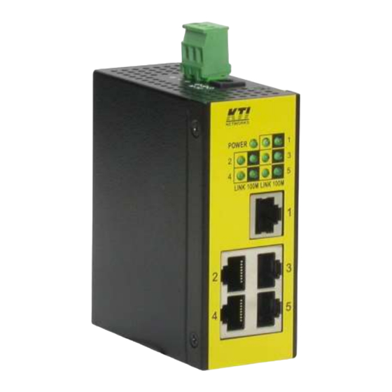
- Page 1 KFS-0540 Ver.B Industrial 5-Port Fast Ethernet Switch Installation Guide DOC.171103...
- Page 2 (C) 2017 KTI Networks Inc. All rights reserved. No part of this documentation may be reproduced in any form or by any means or used to make any directive work (such as translation or transformation) without permission from KTI Networks Inc.
- Page 3 The information contained in this document is subject to change without prior notice. Copyright (C) All Rights Reserved. TRADEMARKS Ethernet is a registered trademark of Xerox Corp. FCC NOTICE This device complies with Part 15 of the FCC Rules. Operation is subject to the following two conditions: (1) This device may not cause harmful interference, and (2) This device must accept any interference received, including the interference that may cause undesired operation.
-
Page 4: Table Of Contents
Table of Contents 1. Introduction ........................... 5 1.1 Features ......................6 1.2 Product Panels ....................6 1.3 LED Indicators ..................... 7 1.4 Specifications ...................... 7 2. Installation ............................. 9 2.1 Unpacking ......................9 2.2 Safety Cautions ....................9 2.3 Mounting the Switch to a Din-Rail ..............10 2.4 Mounting the Switch on a Panel ................ -
Page 5: Introduction
1. Introduction The switch provides five 10/100Mbps copper ports for connections to Ethernet and Fast Ethernet devices. With the featured auto-negotiation function, the switch can detect and configure the connection speed and duplex automatically. The switch also provides auto MDI/MDI-X function, which can detect the connected cable and switch the transmission wire pair and receiving pair automatically. -
Page 6: Features
1.1 Features Auto MDI/MDI-X crossover function on the copper port Support IEEE 802.3x flow control for full-duplex operation Support Back-pressure flow control for half-duplex operation Wide operating temperature range for temperature critical environment Support DIN-rail mounting and panel mounting ... -
Page 7: Led Indicators
1.3 LED Indicators Function POWER Power status Port 1 – Port 5 1 - 5 LINK Link and activity status (Port 1 - Port 5) 100M 100Mbps speed status (Port 1 - Port 5) 1.4 Specifications 10/100 Copper Ports Compliance IEEE 802.3 10Base-T, IEEE 802.3u 100Base-TX Connectors Shielded RJ-45 jacks... - Page 8 Mounting Din-rail mounting Panel mounting (optional) Environmental Operating Temperature Typical C ~ +70 Storage Temperature C ~ +85 Relative Humidity 10% ~ 90% non-condensing Electrical Approvals Part 15 rule Class B EN 55032 Class A EN 61000-6-4 CISPR 32 EN 61000-3-2 EN 61000-3-3 EN 61000-6-2 IEC 61000-4-2...
-
Page 9: Installation
2. Installation 2.1 Unpacking The product package contains: The switch unit for Din-rail mounting One product CD-ROM 2.2 Safety Cautions To reduce the risk of bodily injury, electrical shock, fire and damage to the product, observe the following precautions. -
Page 10: Mounting The Switch To A Din-Rail
2.3 Mounting the Switch to a Din-Rail In the product package, a DIN-rail bracket is provided or has been installed for mounting the switch in a industrial DIN-rail enclosure. The steps to mount the switch onto a DIN rail are: 1. - Page 11 3. Clamp the unit to the DIN rail and make sure it is mounted securely. The final dimension is: -11-...
-
Page 12: Mounting The Switch On A Panel
2.4 Mounting the Switch on a Panel The switches may be provided optionally with a panel mounting bracket. The bracket supports mounting the switch on a plane surface securely. The mounting steps are: 1. Install the mounting bracket on the switch unit. -12-... - Page 13 2. Screw the bracket on the switch unit. 3. Screw the switch unit on a panel and the locations for screws are shown below: -13-...
-
Page 14: Applying Power
2.5 Applying Power The switch provides two types of power interfaces, terminal block and DC power jack for receiving DC power input from external power supply. The DC power requirements no matter which interface is used for the switch are: Operating Vin Voltage Range +7V ~ +30VDC Power Consumption... -
Page 15: Using Terminal Blocks
2.5.1 Using Terminal Blocks 3P Contacts Vin Positive (+) terminal Vin Negative (-) terminal Chassis ground 3P Terminal Plug A plug is provided together with the switch. The plug is shown below: Power Wires 24 ~ 12AWG (IEC 0.5~2.5mm Install the power source wires with the plug properly. Note: When using terminal block connectors, put a cap on the DC jack. -
Page 16: Using Dc Power Jack
2.5.2 Using DC Power Jack When an external power system is not available, the switch provides a DC jack to receive power from typical AC-DC power adapter alternatively. Interfaces DC Jack ( -D 6.3mm / + D 2.0mm) Note: 1. When using DC Jack, put caps on the contacts of the terminal block. 2. -
Page 17: Making Lan Connections
3. Making LAN Connections 3.1 10/100 Copper Ports The 10/100 RJ-45 copper ports support the following connection types and distances: Network Cables 10BASE-T: 2-pair UTP Cat. 3, 4, 5, EIA/TIA-568B 100-ohm 100BASE-TX: 2-pair UTP Cat. 5, EIA/TIA-568B 100-ohm Link distance: Up to 100 meters Auto MDI/MDI-X Function This function allows the port to auto-detect the twisted-pair signals and adapts itself to form a valid MDI to MDI-X connection with the remote connected device automatically.
Need help?
Do you have a question about the KFS-0540 and is the answer not in the manual?
Questions and answers