
Related Manuals for KTI Networks KCD-303P-A1


Summary of Contents for KTI Networks KCD-303P-A1
- Page 1 Industrial 3-Port Fast Ethernet POF Media Converter Switches KCD-303P-A series KCD-303P-B series Installation Guide DOC.081022 1/18...
- Page 2 (C) 2008 KTI Networks Inc. All rights reserved. No part of this documentation may be reproduced in any form or by any means or used to make any directive work (such as translation or transformation) without permission from KTI Networks Inc.
- Page 3 The information contained in this document is subject to change without prior notice. Copyright (C) All Rights Reserved. TRADEMARKS Ethernet is a registered trademark of Xerox Corp. OptoLock is a registered trademark of Firecomms Ltd. FCC NOTICE This device complies with Class B Part 15 the FCC Rules. Operation is subject to the following two conditions: (1) This device may not cause harmful interference, and (2) this device must accept any interference received including the interference that may cause.
-
Page 4: Table Of Contents
1. Introduction ...5 1.1 Features ...6 1.2 Product Panels...6 1.3 Specifications ...7 2. Installation ...9 2.1 Unpacking ...9 2.2 Safety Cautions...9 2.3 Mounting on a Wall ...10 2.4 Panel Mounting ...11 2.5 Din-Rail Mounting...12 2.6 Applying Power with Power Adapter ...13 2.7 Applying Power via USB ...14 3. -
Page 5: Introduction
The switches also provide auto MDI/MDI-X function, which can detect the connected cable and switch the transmission wire pair and receiving pair automatically. This auto-crossover function can simplify the type of network cables used. -
Page 6: Features
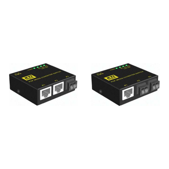
Screw panel-mounting support for industrial enclosure Optional AC-DC power adapters with extended operating temperature range Industrial-rated Emission and Immunity performance 1.1 Features Supports 3 switching-base network segments – [2 x Copper, 1 x POF] and [1 x Copper, 2 x POF] Auto MDI/MDI-X crossover function on the UTP copper port Supports IEEE 802.3x flow control for full-duplex operation Supports Back-pressure flow control for half-duplex operation... -
Page 7: Specifications
KCD-303P-B 1.3 Specifications Copper Ports Compliance IEEE 802.3 10Base-T, IEEE 802.3u 100Base-TX Connectors Shielded RJ-45 jacks Pin assignments Auto MDI/MDI-X detection Configuration Auto-negotiation Transmission rate 10Mbps, 100Mbps Duplex support Full/Half duplex Network cable Cat.5 UTP up to 100 meters POF Ports Connectors OptoLock Optical... - Page 8 Far End Fault Support Enabled Switch Functions MAC Addresses Table 1K entries Forwarding & filtering Non-blocking, full wire speed Switching technology Store and forward Maximum packet length 1552 bytes max. Flow control IEEE 802.3x pause frame base for full duplex operation...
-
Page 9: Installation
2. Installation 2.1 Unpacking The product package contains: The switch unit One AC-DC power adapter One product CD-ROM 2.2 Safety Cautions To reduce the risk of bodily injury, electrical shock, fire, and damage to the product, observe the following precautions. -
Page 10: Mounting On A Wall
2.3 Mounting on a Wall The device can be mounted on a desktop or shelf. Make sure that there is proper heat dissipation from and adequate ventilation around the device. Do not place heavy objects on the device. To mount the device on a wall, one wall mounting hole is provided on the bottom of the device. Hang the device on the wall reliably. -
Page 11: Panel Mounting
2.4 Panel Mounting The switches support panel mounting in industrial enclosure. A panel mounting bracket is required for the mounting. Install the bracket onto the device as shown in the figure below: After bracket installation, the final dimension is shown below: KCD-303P-A KCD-303P-B 11/18... -
Page 12: Din-Rail Mounting
2.5 Din-Rail Mounting To mount the device on a Din-rail, the optional Din-rail mounting bracket is required. Install the bracket onto the device. After bracket installation, the device is ready to be mounted on a din-rail as shown below: 12/18... -
Page 13: Applying Power With Power Adapter
2.6 Applying Power with Power Adapter The device provides a DC power jack for receiving DC power input from an external AC-DC power adapter. Two types of AC-DC power adapters are available for choice. One is with typical operating temperature rating and the other is with extended operating temperature rating for critical applications as follows: Typical Rating: ~ 40... -
Page 14: Applying Power Via Usb
AC power sockets. One optional “USB DC power cable” is available for purchasing to supply power for the switch via USB connection. -
Page 15: Making Lan Connections
If the connected device is also auto-negotiation capable, both devices will come out the best configuration after negotiation process. If the connected device is incapable in auto-negotiation, the switch will sense the speed and use half duplex for the connection. -
Page 16: Making Pof Connections
3.2 Making POF Connections POF Cable Depending on the model specified, two different sizes of POF cables are supported. One is 1.5mm and the other is 2.2mm in diameter. The following figure illustrates 2.2mm POF and Cat.5 as comparison. Easy POF Installation The design of the device enables the POF to be cut and terminated to the exact required length on site, allowing even the most novice user to quickly and easily terminate the bare POF fiber. -
Page 17: Led Indication
The following figure illustrates a connection example between two POF ports located on two devices: Make sure the Rx-to-Tx connection rule is followed on the both ends of the cable. 3.3 LED Indication Function POWER Power status Px Link/Act. Port Px link status State Interpretation The power is supplied to the device. -
Page 18: Applications
4. Applications 4.1 Application in Industrial Networks The following figure illustrates an application example in an industrial network. Four devices are cascaded by POF cables. 4.2 Application For Home Network The following figure illustrates an application example in home network. 4.3 Copper to POF Media Converter Application The following figure illustrates an application of copper Cat.5 to POF media conversion.
Need help?
Do you have a question about the KCD-303P-A1 and is the answer not in the manual?
Questions and answers