Table of Contents
Advertisement
Advertisement
Table of Contents
Troubleshooting

Related Manuals for Man D 2842 LE 620


Summary of Contents for Man D 2842 LE 620
- Page 3 Only use fuel, coolants and lubricants in accordance with MAN regulations, otherwise the manu- facturer’s warranty will not apply! For basic information on the fuels see the publication “Fuels, Lubricants and Coolants for MAN Diesel Engines”. You can find the approved products on the Internet at: −http://www.man-mn.com/ "...
- Page 4 Flat seals / gaskets can be fitted properly only if the following points are observed: D Use only genuine MAN seals/gaskets. D The sealing faces must be undamaged and clean.
-
Page 5: Table Of Contents
............Engine views D 2842 LE 620 . - Page 6 ................Engine lubrication D 2842 LE 620 .
-
Page 7: Engine Type Classification
The system is explained below using the model type D 2842 LE 620 as an example: The “D” at the start of the type classification stands for “Diesel”... -
Page 8: Safety Instructions
Safety instructions General information This brief overview summarises important instructions and is structured into areas of main concern in order to impart the knowledge necessary to prevent accidents involving injury to persons, damage to the engine or other property and harm to the environment. Additional notes are included in the operator’s manual for the engine. - Page 9 D In the event of operational faults immediately identy the cause and rectify to prevent more serious damage. D Always use genuine MAN parts only. Installation of “equally” good parts from other suppliers may cause severe damage for which the workshop carrying out the work is responsible.
- Page 10 Safety instructions 3. Instructions for preventing environmental damage Engine oil and filter cartridges and elements, fuel / fuel filters D Take old oil to an old oil disposal point only. D Ensure without fail that oil and Diesel fuel will not get into the sewerage system or the ground. Caution: Danger of contaminating potable water! D Treat filter elements and cartridges as special waste.
- Page 11 − Wait at least a minute until the pressure in the rail has dropped before loosening a screw connection − If necessary check the pressure drop in the rail with MAN-Cats D Risk of injury! − People with pacemaker must keep at least 20 cm away from the running engine −...
- Page 12 Safety regulations Cleanliness Today modern components of diesel injection consist of high-precision parts which are exposed to extreme stresses. The high-precision technology requires the utmost cleanliness during all work on the fuel sys- tem. Even a particle of dirt over 0.2 mm can lead to the failure of components. The measures described as follows are therefore essential before work begins: Risk of damage from penetration of dirt! D Before working on the clean side of the fuel system clean the engine and the engine...
- Page 13 Safety regulations When carrying out the work it is essential to comply with the following measures: Risk of damage from penetration of dirt! D When the clean side of the fuel system has been opened it is not permissible to use compressed air for cleaning D During assembly work loose dirt must be removed with the aid of suitable extractors (industrial type vacuum cleaners)
-
Page 14: Troubleshooting Table
The subsequent list is meant to be a memory aid so that no causes of damage will be overlooked in the elimination of faults. The precondition for this, however, is that you are familiar with the Repair Manual for the engine and the relevant Operator’s Manual as well as the publication “Fuels, Lubricants, Coolants for MAN Diesel Engines”. - Page 15 Fault table EDC self-diagnosis Starter motor turns over engine slowly or not at all Starter motor turns, engine fails to start, engine fails to start / difficult to start when cold Engine stalls (dies) during operation, no longer starts (starter motor turns), engine fails to start / difficult to start when hot Sudden, temporary engine shutdown, engine does not reach full revs Engine runs at idle speed only, no throttle response...
- Page 16 Power supply to EDC control unit interrupted or battery voltage too low o o o EDC control unit defective (internal fault) Incorrect EDC control unit (check MAN part number) Afterrunning not completed Thermostat defective Engine bearings worn...
-
Page 17: General Notes On Engine Overhaul
D Technically correct installation D Inspection if installation by authorised personnel D Regular maintenance as per maintenance plan D Choice and quality of lube oil, fuel and coolant in accordance with the publication “Fuels, Lubricants and Coolants for MAN Diesel Engines”... -
Page 18: Commissioning After Engine Overhaul
Commissioning after engine overhaul Pressurisation It is extremely important for internal combustion engines (following the completion of repair work, i.e. in their dry state) to be pressurised with lube oil before being recommissioned. This procedure can also be used for ascertaining damage and its causes. If engines are not pressurised, the risk of premature damage to bearing surfaces is very high because it takes a relatively long period of time for the lube oil drawn in from the oil pan via the oil pump to reach the individual bearings. - Page 19 Commissioning after engine overhaul Pressurising an engine affords the following advantages: D All engine parts are lubricated before engine startup; a lubricating film can be built up inside the bear- ings as early as after the first few rotations of the crankshaft, thereby preventing damage to the bearing races D Any loss of oil, be it the result of excessively large bearing play or leaks from the crankcase or from crankcase bores which may not be plugged, can be detected immediately.
-
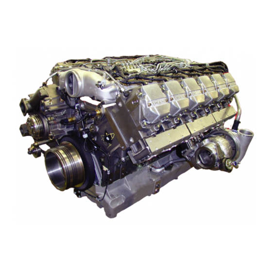
Page 20: Engine Views D 2842 Le 620
Engine views D 2842 LE 620... - Page 21 Engine views D 2842 LE 620 À In take pipe Á Turbocharger  Starter motor à Exhaust manifold Ä Oil sump Å Tension pulley Æ Rail Ç Coolant pump È Oil filter É Oil dipstick Oil separator valve for crankcase breather...
-
Page 22: Engine Lubrication Schedule
Engine lubrication schedule À Oil line to crankshaft Å Oil pump with oil pressure relief valves Á High−pressure pump lubrication Æ Holes for conrod bearing lubrication  Lubricating oil lines to exhaust turbochargers Ç Oil drain screw à Oil return line from exhaust turbochargers È... - Page 23 Engine lubrication schedule À Lubricating oil lines to exhaust turbochargers Å Oil intake pipe Á Rocker arm lubrication Æ Oil pressure relief valves  Piston pin lubrication Ç Oil cooler à Spray nozzles for piston cooling and È Bypass valve cam lubrication É...
-
Page 24: Fuel Diagram
Fuel diagram À Tank Å Fuel pump Á Fuel prefilter with water separator Æ Fuel filter  Injector Ç Fuel distributor à Rail È Solenoid valve Ä High pressure pump É Glow plug... -
Page 25: Schematic Diagram Of Cooling System
Schematic diagram of cooling system À Overflow and vent pipe Æ Filler pipe Á Positive pressure / negative pressure valve Ç Thermostat  Coolant level in surge tank È Engine / crankcase à Surge tank É Water pump Ä Coolant filler neck Å... -
Page 26: Check The Base Fitting Of The High−Pressure Pump
Check the base fitting of the high−pressure pump Check the base fitting of the high− pressure pump Fig. 1 and Fig. 2 For the purpose of checking the start−of−delivery setting, an “OT” (= TDC) mark and a scale from 10...50° before TDC are engraved on a disc Á fitted in front of the torsional vibration damper. - Page 27 Check the base fitting of the high−pressure pump Fig. 5 The indicator (arrow) must then be aligned so that its measuring edge points exactly to the “TDC” mark on the scale disc. Turn engine to ignition TDC 1. Fig. 6 Pull the connector off the rpm sensor Á.
-
Page 28: Removing And Installing The High-Pressure Lines
Removing and installing the high-pressure lines Danger: Before starting the work, comply with “Special instructions when working on the common rail sys- tem” (see page 9). Caution: All connections and removed parts are to be closed immediately with suitable caps! Dirt in the injection system causes: D injectors to jam D the high-pressure pump drive to break... -
Page 29: Removing And Installing High-Pressure Pump
Removing and installing high-pressure pump Removing high-pressure pump D Remove the high-pressure lines between the high-pressure pump and rail, see page 26 Note: The subsequent reinstallation of the high-pressure pump is rendered considerably easier if before its removal the engine has been turned to ignition TDC cylinder 1(see page 24). Danger: Before starting the work, comply with ”Special instructions when working on the common rail sys- tem”... - Page 30 Removing and installing high-pressure pump Installing high-pressure pump D Turn engine to ignition TDC 1. Fig. 4 Turn mark “TOP” on the high-pressure pump drive gear in the middle to pump. Insert high-pressure pump. Fig. 5 Tighten the mounting bolts in the sequence and method specified (pos.
-
Page 31: Removing And Installing The Rail
Removing and installing the rail Danger: Before starting the work, comply with “Special instructions when working on the common rail sys- tem” (see page 9). Caution: All connections and removed parts are to be closed immediately with suitable caps. Dirt in the injection system causes: D injectors to jam D the high-pressure pump drive to break The lines contain fuel. - Page 32 Removing and installing the rail Install rail Install the filter in reverse order: D Install rail and fuel pipe for rail return D Fit high-pressure pipes Danger: High-pressure lines with WAF 17 union nuts must be replaced. High-pressure lines with WAF 19 union nuts may be reused.
-
Page 33: Removing And Installing The Rail Pressure Sensor, Pressure Relief Valve
Removing and installing the rail pressure sensor, pressure relief valve Danger: Before starting the work, comply with “Special instructions when working on the common rail sys- tem” (see page 9). Caution: All connections and removed parts are to be closed immediately with suitable caps! Dirt in the injection system causes: D injectors to jam D the high−pressure pump drive to break... -
Page 34: Removing And Installing The Injectors
Removing and installing the injectors Danger: Before starting the work, comply with ”Special instructions when working on the common rail sys- tem” (see page 9). Caution: All connections and removed parts are to be closed immediately with suitable caps! Dirt in the injection system causes: D injectors to jam D the high-pressure pump drive to break The lines contain fuel! - Page 35 Removing and installing the injectors Fig. 4 Remove coolant bleed pipe, rail carrier and leak-oil pipe. Fig. 5 and Fig. 6 Unscrew the mounting bolt Á of the connector fit- ting and pull the pressure pipe fittings  out of the cylinder head.
- Page 36 Removing and installing the injectors Fig. 8 Use a support bridge À and extractor tool Á (see page 172) to pull out the injector and pressure flange. D Push the extractor tool Á through the support bridge À over the injector, making sure that the clamping sleeve is turned back far enough D Tension the clamping sleeve and pull the injec- tor with knurled nut out of the cylinder head...
- Page 37 Removing and installing the injectors Fig. 11 and Fig. 12 Caution: Removed pressure pipes must be re- placed. Insert pressure pipe into the cylinder head. Caution: The thin end of the pressure pipe points towards the injection nozzle. Replace the O-ring and apply a light coating of grease.
- Page 38 Removing and installing the injectors Fig. 15 Install rail carrier, coolant bleep pipe and cable har- ness for injector. Connect cable harness to the injectors. Tightening torque: 1.5 Nm Fig. 16 Fit valve cover with seal and tighten mounting bolts. D Installing rail, see page 30 D Fill coolant, see page 40...
-
Page 39: Fuel Prefilter With Water Separator
Fuel prefilter with water separator Fuel pre-filter with water separator Fig. 1 Draining water: D Open drain screw À and let off water D Close drain screw À again Changing filter element Only when the engine is switched off Close shut-off valves between engine, pre-filter and tank. -
Page 40: Fuel Filter, Exchanging Filter Cartridge
Fuel filter, exchanging filter cartridge Changing fuel filter cartridge Only when the engine is swiched off. Close shut-off valves between engine, pre-filter and tank. Fig. 1 D Loosen filter cartridge by means of tape wrench, unscrew it by hand and take it off D Moisten the seals on the new filter cartridge with fuel D Screw on the filter cartridges and tighten them... -
Page 41: Flame-Starter Sheathed-Element Glow Plug, Removing And Installing
Flame-starter sheathed-element glow plug, removing and installing Removing sheathed-element glow plug Fig. 1 Disconnect the electric connections from the sheathed-element glow plug. Remove fuel line carefully. Loosen counter nut on sheathed-element glow plug and remove glow plug. Installing sheathed-element glow plug Fig. -
Page 42: Draining And Filling Coolant
The cooling system of the engine is to be filled with a mixture of drinking water from the mains and anti- freeze based on ethylene glycol and / or anticorrosion additive. See Publication “Fuels, Lubricants and Coolants for MAN Diesel Engines”. Coolant must be poured in according to the vehicle manufacturer’s filling specifications. -
Page 43: Removing And Installing Thermostats
Removing and installing thermostats Fig.1 D Draining off coolant, see page 40 Remove the three mounting bolts from the coolant neck and take off coolant neck. Fig. 2 Take out short-circuit inserts / thermostats. Check the function of the thermostats as fol- lows. -
Page 44: Removing And Installing Coolant Pump
Removing and installing coolant pump Note: Exchange or repair coolant pump only if it has been found to be leaky. The design of the coolant pump mechanical cassette seal permits small amounts of coolant to pass through it. This coolant passing through results in a trace of drained coolant below the drain bore. - Page 45 Removing and installing coolant pump Installing coolant pump Fig. 3 Clean the sealing faces on coolant pump and en- gine housing. Fit coolant pump with new seal. Fit the mounting bolts. Fig. 4 Coolant pumps with high-temperature and low-temperature sections To aid in assembly pins (special tool, see page 171, no.
-
Page 46: Repairing Coolant Pump With High-Temperature And Low-Temperature Parts
Repairing coolant pump with high-temperature and low-temperature parts Coolant pump for three thermostats Fig. 1 and 2 1 Pump housing HT (high-temperature part) 2 Pump housing LT (low-temperature suction part) 3 Hub 4 Bolt DIN 931−M8x155, hex nut DIN 934−M8 5 Bolt DIN 933−M8x35−8.8 6 Mechanical seal 51.06520−0085 7 Impeller for coolant pump, HT circuit... - Page 47 Repairing coolant pump with high-temperature and low-temperature parts Fig. 5 Knock out cover by driving a suitable mandrel under it (Fig. 1, item 3) at notch (arrow). Fig. 6 Pull impeller off coolant pump shaft. For this purpose four threaded bores M8 are pro- vided.
- Page 48 (may be possible by hand). Install mechanical seal while “wet”, i.e. to install it, coat holding sleeve and water pump shaft with a mixture of either 50% water and 50% cleaning spirit or 40% to 50% antifreeze agent as per MAN 324 and water.
- Page 49 Repairing coolant pump with high-temperature and low-temperature parts Fig. 12 Note: Brace the bearing shaft. Slowly press impeller on to bearing shaft to ensure +0,4 correct gap (0,5 Fig. 13 Press in new mechanical seal (pos. 8) with press- fitting sleeve (special tool) until it stops. Observe installation note for seal on page 50.
- Page 50 Repairing coolant pump with high-temperature and low-temperature parts Fig. 16 Note: For subsequent steps brace the bearing shaft. Press grooved ball bearing 6003 into position using special tool. Fig. 17 Press in new mechanical seal (pos. 6) with press- fitting sleeve (special tool) until it stops. Observe installation note for seal on page 50.
- Page 51 Repairing coolant pump with high-temperature and low-temperature parts Fig. 20 Fit new pump cover and press it into housing, using a suitable pressing tool. Attach water pump with new seal, see page 42.
- Page 52 Install mechanical seal while “wet”, i.e. to install it, coat holding sleeve and water pump shaft with a mixture of either 50% water and 50% cleaning spirit or 40% to 50% antifreeze agent as per MAN 324 and water. Other antiseize agents must not be used.
-
Page 53: Cleaning Cooling System
Cleaning cooling system Cleaning inside of cooling system Tests have shown that in many cases the poor condition of the coolant and / or the cooling system ac- counts for damage to the coolant pump seal. The poor condition of the cooling system is normally due to the use of unsuitable or no antifreeze or corrosion inhibitor or to defective caps for filler necks and service valves which are not punctually replaced. - Page 54 Cleaning cooling system Removing lime deposits in cooling system Proceed as follows: D Drain coolant D Fill the system with undiluted original pickling fluid (lithsolvent acid or engine pickling fluid RB-06). Keep the engine running for approx. 8 hours with this fluid in the system (also in normal operation) D Drain the pickling fluid and flush the system thoroughly with tap water D If necessary, refill the system with fresh pickling fluid and pickle the system for a further 8 hours D Drain the pickling fluid, fill the system with tap water, and run the engine at idle for 5 minutes to flush out...
-
Page 55: Changing Oil Filter
Changing oil filter Caution: Used oil and oil filters are classed as dan- gerous waste and must de disposed of accordingly. Note instructions for prevent- ing environmental damage. Fig. 1 Open oil drain plug on oil filter can and use con- tainer to catch oil that may emerge. -
Page 56: Removing And Installing The Oil Cooler
Removing and installing the oil cooler D Draining off coolant, see page 40 D Removing the oil filter, see page 53 Caution: Old oil and used oil filters are hazardous waste. Observe safety instructions for the pre- vention of environmental damage. Fig. -
Page 57: Removing And Installing, Repairing Oil Pump
Removing and installing, repairing oil pump Drain engine oil Danger: The oil is hot, risk of scalding! Do not touch the oil drain plug with bare fingers. Oil is an environmental hazard. Handle with care! Fig. 1 and Fig. 2 With the engine at operating temperature, remove the oil drain plugs on the oil sump and the oil filter bowl and allow the old oil to drain off completely. - Page 58 Removing and installing, repairing oil pump Fig. 5 Unscrew the mounting bolts of the pressure relief valve and oil pump. Take off overpressure valve and oil pump. The overpressure valve is encapsulated. Opening pressure, see “Service Data”. Note: Depending on the engine model and oil pan variant, various oil pump versions are possible.
- Page 59 Removing and installing, repairing oil pump Fig. 9 Fit on the cover. Tighten the mounting bolts with the prescribed torque. Grind or exchange heavily worn covers. Checking the axial clearance of the pump wheels Fig. 10 Position dial gauge and push shaft up to the stop in one direction and set dial gauge to ”0”.
- Page 60 Removing and installing, repairing oil pump Filling with engine oil Caution: Do not add so much engine oil that the oil level rises above the max. marking on the dipstick. Overfilling will result in damage to the engine. Fig. 13 and Fig. 15 Refill with fresh engine oil at the oil filler neck À.
-
Page 61: Oil Injection Nozzle
Oil injection nozzle Removing the oil injection nozzle D Draining off oil, see page 55 D Removing the oil pan, see page 55 Fig. 1 Unscrew the securing bolts of the oil injection nozzle (arrow). Remove oil injection nozzle with valve. Check the oil injection nozzle valve Fig. - Page 62 Oil injection nozzle Fig. 5 The oil spray from each nozzle must reach the entry bore hole of the cooling duct in the piston crown À and cams Á without hindrance. Bent oil injection nozzles must on no account be repaired.
-
Page 63: Removing And Fitting Vibration Damper, Replacing Front Crankshaft Gasket
Removing and fitting vibration damper, replacing front crankshaft gasket Removing vibration damper D Relax and remove V-belt; see page 132 D Turn engine to ignition “TDC”. This ensures that in subsequent assembly work the indicating dial will be in the correct position Fig. - Page 64 Removing and fitting vibration damper, replacing front crankshaft gasket Replacing the front crankshaft gasket Fig. 4 Loosen the mounting bolts of the cover. Fig. 5 Remove the cover. Only replace the front crankshaft gasket as a com- plete unit, i.e. replace the bearing race and the radial shaft sealing ring.
- Page 65 Removing and fitting vibration damper, replacing front crankshaft gasket Fig. 8 A special too is required to fit the bearing race. Clean the inside of the bearing race and tail shaft. Coat the tail shaft with sealing compound “Antipor 46”. D Push race À...
- Page 66 Fitting the vibration damper Fig. 12 Position the oil thrower on the crankshaft. Position the vibration damper on two guide man- drels (M16x1.5). Ensure that the position of the graduated disc relative to the crankshaft is correct. Tighten the mounting bolts with the prescribed torque.
-
Page 67: Removing And Installing Flywheel,Replacing Starter Gear Ring
Removing and installing flywheel,replacing starter gear ring Removing flywheel D Remove speed pickup, see page 133 Fig. 1 Release the mounting bolts, securing the engine against rotating if necessary. Fig. 2 Unscrew two bolts opposite one another and re- place with two guide mandrels (special tool). Remove all the bolts. - Page 68 Removing and installing flywheel,replacing starter gear ring Replacing starter ring gear Fig. 5 Remove the flywheel. Drill the starter motor toothed wheel and break with a chisel. Caution: In doing so, do not damage the flywheel. Fig. 6 Note: As the maximum axial run-out of the starter motor toothed wheel must not be exceeded, the axial run-out of the fly- wheel should be measured on the contact...
-
Page 69: Replacing Crankshaft Seal (Flywheel End)
Replacing crankshaft seal (flywheel end) Removing shaft sealing ring Fig. 1 Remove flywheel, see page 65. Prisey out the insulation ring with the special tool or a screwdriver Fit shaft sealing ring Fig. 2 When fitting a new shaft seal, you should also ex- change the bearing race of the flywheel. -
Page 70: Replacing The Bearing Race
Replacing the bearing race Replacing bearing race Remove flywheel, see page 65. Fig. 1 If the shaft sealing ring on flywheel side is re- placed, it is also recommended to replace the bearing race of the flywheel. Pull off the bearing race to be exchanged using a puller (special tool, see Page163, no. -
Page 71: Crankshaft Gaskets
Crankshaft gaskets General information on crankshaft seals As a general principle, the radial shaft sealing rings are made of polytetrafluorothylene (PTFE), otherwise known as Teflon. PTFE sealing rings differ from the elastomer sealing rings that used to be common in that they have a much wider, flat sealing lip that is not pretensioned by a coiled spring expander. -
Page 72: Removing And Installing Intake Manifold
Removing and installing intake manifold Note: When carrying out work on the intake system, ensure meticulous cleanliness to prevent dirt and foreign matter from pen- etrating into the system. Removing intake manifold Fig. 1 Removing intake manifold. Remove the injection lines, see page 32 Fig. -
Page 73: Removing And Installing Exhaust Pipe
The exhaust pipe is heavy. Before unscrewing all securing bolts, if appropriate replace 2 bolts by stud bolts as guides. The stud bolts with thread M10 have been pro- duced by MAN. Remove exhaust pipe. Installing the exhaust pipe Fig. 3 Before fitting the exhaust pipe, screw in 2 stud bolts as a guide. -
Page 74: Turbocharger, Trouble Shooting
Turbocharger, trouble shooting Before removing the turbocharger carry out the following checks Turbochargers are frequently exchanged if the oil consumption is too high, the output too low or the intake and / or exhaust gas noises appear to be abnormal. Subsequent inspections by the manufacturer of the supposedly defective parts frequently prove the turbo- chargers to be in order. - Page 75 − The engine is overfilled with oil D Check whether the correct dipstick and guide pipe combination is installed − The engine oil used is unsuitable (see publication “Fuels, Lubricants, Coolants for MAN Diesel Engines”) − The engine is being run on impermissibly steep inclines −...
-
Page 76: Checking The Charge-Air Pressure
Extreme operating conditions (full-load operation and high air temperature) and the use of unsuitable en- gine oils (also see publication “Fuels, Lubricants, Coolants for MAN Diesel Engines”) may cause deposits on the compressor as well as in the intercooler, which results in a reduction in charge-air pressure. -
Page 77: Removing And Installing Turbocharger
Removing and installing turbocharger Removing turbocharger Fig. 1 Remove the charge−air elbow and the charge−air pipes leading to the turbocharger. Fig. 2 Detach intake neck. Fig. 3 Remove oil pressure line from turbocharger. Fig. 4 Remove oil return line from turbocharger. - Page 78 Removing and installing turbocharger Fig. 5 Remove the bolts from the turbocharger. Take off turbocharger. Note: When placing the turbocharger to one side, ensure extreme cleanliness to pre- vent penetration of dirt and foreign bodies. Installing turbocharger Fig. 6 The turbocharger is fitted in reverse order. On assembly, new gaskets and new self−locking nuts are to be used.
-
Page 79: Checking Axial And Radial Clearance Of Turbocharger Rotor Shaft
Checking axial and radial clearance of turbocharger rotor shaft D Remove turbocharger, see page 75 D Mark turbine housing relative to the bearing housing D Remove turbine housing Axial clearance Fig. 1 Apply dial gauge holder and dial gauge under pre- load to shaft end face of the turbine wheel as shown. -
Page 80: Removing And Installing The Cylinder Head
Removing and installing the cylinder head Removing cylinder head D Drain off coolant, see page 40 D Removing injectors, see page 32 D Remove exhaust pipe, see page 71 D Remove intake pipe, see page 70 Fig. 1 Remove the cylinder head covers. Remove the coolant bleed pipe. - Page 81 Removing and installing the cylinder head Installing cylinder head Fig. 5 Before fitting, clean and blow out the threaded holes in the crankcase. Clean the sealing surfaces on the cylinder head and on the crankcase. Lay the new cylinder head seal in place, ensuring that the hole patterns match up, and place the cyl- inder head on top.
- Page 82 Removing and installing the cylinder head Fig. 9 Check cylinder head bolts for max. permitted length (see “Service Data”). Removed bolts can be reused if the max. permitted length is not ex- ceeded. Before inserting the cylinder−head bolts, apply en- gine oil to the thread and coat the seating surface of the bolt head with installation paste “Optimoly White T”.
- Page 83 Removing and installing the cylinder head General notes The sealing effect of the cylinder head seal depends mainly on whether the required initial tension of the cylinder−head bolt is actually achieved and retained. To tighten the cylinder−head bolts, use a calibrated torque wrench. The specified final torque must be main- tained for at least 5 seconds when it is applied.
-
Page 84: Setting The Valve Clearance
TDC and the rocker arms are relieved of load. The valves of the synchronised cylinder are then on overlap. Fig. 3 D 2842 LE 620 Valves overlap in cylinder 1 12 3 10 2 11... -
Page 85: Dismantling And Assembling The Rocker Arm Mechanism
Dismantling and assembling the rocker arm mechanism Disassembling rocker arm mechanism D Remove cylinder head, see page 78 Fig. 1 Clamp mounting plate Á (special tool) in a vice and bolt the rocker arm bearing housing onto the mounting plate. The exhaust valve rocker arm shaft has a tapped hole. - Page 86 Dismantling and assembling the rocker arm mechanism Fig. 5 À Rocker arm shaft for exhaust valves Á Rocker arm shaft for inlet valves  Rocker arm Assembling rocker arm mechanism Fig. 6 and Fig. 7 Recesses À in the rocker arm shafts serve to ac- commodate the cylinder head bolts Á.
- Page 87 Dismantling and assembling the rocker arm mechanism Fig. 9 Bolt the guide plate onto the rocker arm bearing shaft − with “TOP” facing the intake side. Fig. 10 Insert press−in part “A” for the exhaust−side shaft into the guide plate, ensuring that the alignment pins fit into the shaft bores.
- Page 88 Dismantling and assembling the rocker arm mechanism Fig. 13 Remove the press−in tool. Check the rocker arms for ease of movement and axial play.
-
Page 89: Removing And Installing Valves
Removing and installing valves Removing valves D Remove cylinder head, see page 78 Fig. 1 Special tools for removing and installing the valve springs: À Assembly plate for cylinder head and rocker arm bearing housing (not in tool case) Á Anchor plate with grid part Â... - Page 90 Removing and installing valves Fig. 5 Feed mounting cartridge Æ with sleeve È (small dia.) into the guide sleeve and using the knurled grip insert the holder into the joint between the re- taining wedges. Fig. 6 Attach pressure fork Ä and press down as far as possible with the mounting cartridge.
- Page 91 Removing and installing valves Fig. 9 Remove the valve stem seals with a quick gripper (if available). Fig. 10 Remove the washers for the valve springs. Fig. 11 Turn the cylinder head over and remove the valves. Clean parts. Inspect the valve stem for pitting and wear. Inspect the valve guides for wear;...
- Page 92 Removing and installing valves Installing valves Fig. 13 Lubricate the valves at the stems and insert in the correct valve guides. D Small valve plate recess = intake valve D Large valve plate recess = exhaust valve Fig. 14 Turn the cylinder head over and secure to the mounting plate.
- Page 93 Removing and installing valves Fig. 17 Press in the valve stem seal as far as it will go. Remove the guide sleeve. Fig. 18 Mount the valve springs and spring seats. Fig. 19 Fit guide sleeve à over the valve spring for cen- tring.
- Page 94 Removing and installing valves Fig. 21 The valve tapers must snap reliably into place when the pressure fork is released. Caution: Make sure the valve tapers are correctly seated as tapers which spring out may cause serious engine damage. Measuring valve recess Fig.
-
Page 95: Removing And Installing Valve Guides
Removing and installing valve guides D Removing and installing cylinder head, see page 78 D Remove and install valves, see page 87 Fig. 1 Special tool for removing and installing the valve guides and valve seats: À Press-in plates for valve seat inserts Á... -
Page 96: Replacing Valve Seat Insert
Replacing valve seat insert Removing valve seat insert Note: If the valve seat inserts are replaced, the valve guides must be replaced at the same time as otherwise exact refacing of the valve seat inserts cannot be guaranteed. For the above−mentioned reasons, the tool for removing and installing the valve guides and valve seat inserts have been designed in such a way that, when this tool is used, the valve guides and the valve seat inserts can be replaced only together or only the valve guides alone can be re- placed. - Page 97 Replacing valve seat insert Installing valve seat insert Fig. 4 Chill the new valve seat insert down to approx. −200°C and insert in the cylinder head (approx. 20°C room temperature). Carry out a check by driving it in as far as it will go using a pressing tool.
-
Page 98: Reworking Valve Seat
Reworking valve seat Reworking valve seat (with Mira precision valve seat machining tool) Fig. 1 À Driving crank Á Toggle switch  Handle à Lubricating nipple Ä Mains connection Å Magnetic flange with coil Æ Guide pipe Ç Slewing arm È... - Page 99 Reworking valve seat Fig. 4 Release the Jaccard lever, set the magnetic flange down flat on the clamping plate and adjust the height so that the forming cutter does not contact the valve seat. Set the toggle switch to position 1. Tighten the Jaccard lever.
- Page 100 Reworking valve seat Fig. 8 When reworking the valve seat inserts, remove as little material as possible from the seat face. The valve recess serves as the reference value. Fig. 9 The valve seat insert must be changed if as a re- sult of the cylinder head interface and the valve seat insert having been machined the theoretical valve seat is too deep in the cylinder head or the...
-
Page 101: Refacing Valves
Refacing valves Fig. 1 Apply abrasive paste to the tapered area of the valve seat. Lubricate the valve guide and insert the valve. Fig. 2 Use a valve grinder to reface the valve seat by ap- plying moderate axial pressure and describing a turning motion. -
Page 102: Removing And Installing The Gear Case
Removing and installing the gear case Removing the gear case D Removing the starter motor, see page 130 D Removing the flywheel, see page 65 Fig. 1 Oil and coolant lines, brackets for wiring harnesses etc. are attached to the timing case, and these must be removed. - Page 103 Removing and installing the gear case Fig. 5 Tighten the bolts with the prescribed torque. Tighten the mounting bolts of the oil pan. Clean gasket residues from the sealing surface of the timing case cover. Screw the timing case cover on with a new seal. Secure the oil and coolant lines.
-
Page 104: Removing And Installing Camshaft
Removing and installing camshaft Removing camshaft D Draining off coolant, see page 40 D Removing the oil pan, see page 55 D Removing the starter motor, see page 130 D Removing the flywheel and timing case, see page 100 D Removing cylinder heads, see page 78 Note: The engine must be turned through 180_ in order to remove the camshaft. - Page 105 Removing and installing camshaft Installing camshaft Fig. 3 Oil and insert the valve tappets. Oil the camshaft bearing bushings. Fit inserting mandrel (special tool) to the camshaft. Oil the camshaft and insert carefully. Caution: Do not damage the bearings. Fig. 4 In doing so, note the marking of the crankshaft and camshaft toothed gear.
- Page 106 Removing and installing camshaft Measuring the axial clearance of the camshaft Fig. 6 Remove screw plug or angle drive for tachometer from camshaft cover. Apply the sensor of the dial gauge to the front of the camshaft or driver for the revcounter. Set the dial gauge to ”0”.
-
Page 107: Removing And Fitting Camshaft Bearing Bushes
Removing and fitting camshaft bearing bushes Removing the camshaft bearing bushes Note: The engine is equipped with 7 camshaft bearings. Bearing no. 1 is located on the counter-flywheel side. Press out the camshaft bearing bush, bearing 1 Fig. 1 Use the impact extractor (special tool) to pull out the bearing bush of bearing 1 from the counter-fly- wheel side. - Page 108 Removing and fitting camshaft bearing bushes Fig. 5 Use a soft hammer (plastic or copper) to knock out camshaft bearing bushes 2, 3 and 4 in succession. Press out the camshaft bearing bush, bearing 7 Fig. 6 Use the impact extractor (special tool) to pull out the cam bearing bush of bearing 7 from the fly- wheel side.
- Page 109 Removing and fitting camshaft bearing bushes Fig. 9 Place the press-out plate  from the other side of the stop onto the shaft and insert in bearing bush 6. Here, insert the guide bush Á with the larger diam- eter in the bearing hole and let the spring-loaded balls lock into the oil holes.
- Page 110 Removing and fitting camshaft bearing bushes Fitting the camshaft bearing bushes Fig. 11 Depending on the number of the camshaft bearing, there are various press-in plates (special too) for pressing in the bearing bushes À Shaft with groove and fixed stop Á...
- Page 111 Removing and fitting camshaft bearing bushes Fig. 15 Place the press-in plate Å with fitted bearing bush on the shaft. The press-in plate is fixed in place by the groove so that the oil holes line up after pressing in. Fig.
- Page 112 Removing and fitting camshaft bearing bushes Fig. 19 From the counter-flywheel side, insert the press- out plate à in bearing 2. Insert the shaft with guide bush  through bearing 1, then through the press-out plate à (bearing 2). Here, insert the guide bush  with the small diam- eter in the bearing hole and let the spring-loaded balls lock into the oil holes.
- Page 113 Removing and fitting camshaft bearing bushes Figs. 23 and 24 Arrangement of special tools: À Shaft with groove and fixed stop à Press-out plate for bearing bushes 2 to 6 as additional guide Ä Press-in plate for bearing bush 1 Å...
- Page 114 Removing and fitting camshaft bearing bushes Fitting camshaft bearing bushes, bearings 3 and 4 Fig. 27 Special tool for pressing out bearing bushes 5, 6 and 7 from the mounting tool: À Shaft with groove and fixed stop Á Striking weight for À Â...
- Page 115 Removing and fitting camshaft bearing bushes Fig.31 Place the bearing bush with edge on the press-in plate. Caution: D One oil hole of the bearing bush must be fixed in place by the spring-loaded ball D The other oil hole must be flush with the recess of the press-in plate D The bearing bush must be seated up to the stop on the press-in plate...
-
Page 116: Checking The Valve Timing
Checking the valve timing Note: Unsynchronised valve timing can cause severe engine damage. For this reason, following engine faults that can cause twisting of the shrunk−on cam- shaft toothed wheel, the correct seating must be checked by checking the valve timing. -
Page 117: Removing And Installing Crankshaft
Removing and installing crankshaft Removing crankshaft D Remove oil pan and oil pump, see page 55 D Remove timing case, see page 100 D Remove front cover of crankshaft seal, see page 61 D Remove all pistons with connecting rods, see page 118 Fig. - Page 118 Removing and installing crankshaft Check the spread of the bearing bushes Fig. 5 Place the bearing shells together on a level sur- face. Measure and note down dimensions “A” and “B”. Spread dimension = A−B Installing crankshaft Fig. 6 and Fig. 7 Clean the oil ducts in the crankcase and in the crankshaft with dry compressed air.
- Page 119 Removing and installing crankshaft Fig. 9 Caution: Removed bolts must be replaced. Screw in the crankshaft bearing cover bolts and tighten them. Pretightening: 80−90 Nm 1st angle tightening: 905 2nd angle tightening: 905 Check that the crankshaft runs smoothly. Caution: Damaged bearing caps cannot be replaced on an individual basis.
-
Page 120: Removing And Installing Pistons With Conrods
Removing and installing pistons with conrods Removing pistons with conrods D Removing oil pan, see page 55 D Removing cylinder heads, see page 78 Fig. 1 Loosen and remove conrod bearing cover bolts. Fig. 2 Take off conrod bearing covers with bearing bushes;... - Page 121 Removing and installing pistons with conrods Installing pistons with conrods Note: If the pistons have to be replaced, it must be determined whether oversize pistons were fitted by measuring the pistons or re- ading off the dimension on the piston crown.
- Page 122 Removing and installing pistons with conrods Fig. 9 Place the conrod bearing cover in position. Caution: The numbers on the connecting rod bear- ing cap and connecting rod big end must be on one side. Fig. 10 Screw in the conrod bearing bolts and tighten them in stages.
-
Page 123: Removing Pistons From Conrod And Fitting, Checking − Replacing Conrod
Removing pistons from conrod and fitting, checking − replacing conrod Removing pistons from conrod and fit- ting Fig. 1 Remove pistons with conrods. Clamp the conrod in a vice using protective jaws. Disengage piston pin fastening. Fig. 2 Press out the gudgeon pin, in doing so, hold the piston. - Page 124 Removing pistons from conrod and fitting, checking − replacing conrod Fig. 5 Clean conrod. Inspect for external damage, re- place damaged conrods if necessary. Check parallel location of conrod and twisting of piston pin eye to bearing bush bore hole. In the case of deviations beyond the tolerance range, replace conrod.
-
Page 125: Removing And Installing Piston Rings
Removing and installing piston rings Piston ring arrangement Fig. 1 À Compression ring (double−sided keystone ring) Á Compression ring (tapered compression ring) Â Oil scraper ring (bevelled−edge ring) Removing piston rings Fig. 2 Remove pistons with conrods. Fit conrod in a vice, use protective jaws. Set piston ring wrench to piston diameter. - Page 126 Removing and installing piston rings Installing piston rings Fig. 5 and Fig. 6 use the piston ring wrench to engage the piston rings in the relevant piston ring groove (TOP facing upwards). Checking piston ring axial clearance Fig. 7 Determine the piston ring clearance in each piston ring groove at various points using a feeler gauge.
-
Page 127: Replacing Cylinder Liners
Replacing cylinder liners Removing cylinder liners Note: Observe oversizes for cylinder liner out- side diameters and collar heights (see “Service data”). D Remove cylinder head, see page 78 D Remove piston, see page 118 Fig. 1 Special tool for removing the cylinder liners. Fig. - Page 128 Replacing cylinder liners Fig. 5 Set the cylinder liner down in an upright position. Remove the O-rings. Number cylinder liners in order of installation. Fig. 6 Remove the O-rings from the crankcase. Clean the seat for the cylinder liners in the crank- case.
- Page 129 Replacing cylinder liners Installing cylinder liners Checking cylinder liner protrusion Fig. 7 Clean the basic bore and the cylinder liner. Insert the cylinder liner without O-rings into the crankcase, observing the marking (ensure that it is identical to the position prior to removal). Using the dial gauge and its holder, measure the cylinder liner protrusion at no less than 4 different points.
- Page 130 Replacing cylinder liners Fig. 10 Insert new O-rings for the lower seal (144x4) dry into the crankcase. Fig. 11 Insert new O-rings for the upper seal (138x2) into the cylinder liner grooves. Do not overstretch the O-rings. Note: Do not use grease or sealing compounds of any type to install the cylinder liners and O-rings.
-
Page 131: Measuring Piston Protrusion
Measuring piston protrusion Measuring piston protrusion Fig. 1 Remove the cylinder heads. Turn the piston to be measured to TDC. Apply the dial gauge bracket with dial gauge to the crankcase gasket surface. Set the dial gauge to ”0”. Fig. 2 Carefully swing the dial gauge bracket around while raising the tip of the dial gauge. -
Page 132: Removing And Installing Starter Motor
Removing and installing starter motor Fig. 1 Disconnect the negative lead from the battery or, if fitted, switch off the battery master switch. Disconnect connection cable terminal 31 (negative pole, thick cable), connection cable terminal 30 (positive pole, thick cable) and terminals 48 and 50 from the starter. -
Page 133: Belts
V−belts V−belts Checking condition D Check V−belts for cracks, oil, overheating and wear D Change demaged V−belts If, in the case of a multiple belt drive , wear or differing tensions are found, always replace the complete set of belts. Checking tension Use V−belt tension tester to check V−belt tension. -
Page 134: Tensioning And Changing V−Belt
V−belts Tensioning and changing V−belt Crankshaft − water pump − tension pulley D Remove fixing bolts À D Release lock nut Á D Turn adjusting nut  until the V−belt is correctly tensioned D Retighten lock−nut and fixing bolts To change the V−belt, turn back the setting nut and swivel the tension pulley inwards. -
Page 135: Removing And Installing Speed Pickup
Removing and installing speed pickup Fig. 1 The speed pickup and the auxiliary speed pickup are fitted to the flywheel housing, at bottom right. Only the lower transmitter is installed on engine D 2842 LE 620. For removal, disconnect cable from plug connec- tion (arrow). -
Page 137: Service Data
Service Data... -
Page 138: Specifications
Specifications Engine D 2842 LE 620 Design .......... -
Page 139: Crankcase
Dimensions Service Data Limit values Crankcase standard size: 153,90−154,00 mm for liners with larger outer diameter: 0,5 and 1,0 mm: 54,40−154,50 mm Ø standard size: 145,80−145,84 mm Ø for liners with larger outer diameter: 0,5 mm: 146,30−146,34 mm 1,0 mm: 146,80−146,84 mm 9,97−9,99 mm standard size:... -
Page 140: Crankshaft
Dimensions Service Data Limit values Crankshaft Crankshaft front end (opposite end to flywheel) 99,985−100,020 mm Standard size: 89.98−90.00 mm undersize −0.25: 89.73−89.75 mm undersize −0.50: 89.48−89.50 mm undersize −0,75: 89.23−89.25 mm undersize −1.00: 88,98−89,00 mm Standard size: 103.98−104.00 mm undersize −0.25: 103.73−103.75 mm undersize −0.50: 103.48−103.50 mm... - Page 141 Dimensions Service Data Limit values Crankshaft rear end (adjacent to flywheel) Max. permissible runout with crankshaft taken up in end bearings: D 2842 at bearing 4 0,08 mm Standard size: 38.000−38.062 mm undersize −0.25: 38.500−38.562 mm undersize −0.50: 38.500−38.562 mm undersize −0.75: 39.000−39.062 mm undersize −1.00:...
- Page 142 Dimensions Service Data Limit values Thrust bearing Standard size: 37.74−37.81 mm undersize −0.25: 38.24−38.31 mm undersize −0.50: 38.24−38.31 mm undersize −0.75: 38.74−38.81 mm undersize −1.00: 38,74−38,81 mm Spread: 0,1−0,5 mm Marking: top / bottom standard size: 0164 / 0165 mm undersize −0.25: 0168 / 0169 mm undersize −0.50:...
-
Page 143: Flywheel And Starter Gear Ring
Dimensions Service Data Limit values Flywheel and starter gear ring Ø Flywheel: 432,490−432,645 mm Internal gear ring Ø: 432,000−432,155 mm Interference: 0,335−0,645 mm Installation temperature: 200−230_C m = 54,2 kg (with gear ring) Ø J = 1,98 kgm Number of teeth: Z = 160, module 3 Matching gear: Starter pinion (Z = 9) Backlash: 0,6−0,9 mm... -
Page 144: Conrods
Dimensions Service Data Limit values Conrods 46,055−46,065 mm Wear limit: 46,09 mm Bearing bore in measuring directions 1, 2 and 3 and in measuring planes a and b: 90,064−90,106 mm 8 mm 8 mm Edge condition: New conrod bearing in place, conrod as- sembled Conrod bearings Standard size:... -
Page 145: Pistons
Dimensions Service Data Limit values Pistons Compression height: 81,250−81,300 mm Piston protrusion above crankcase top: 0,01−0,38 mm Ø 46,030−46,040 mm Piston bolt diameter: 45,994−46,000 mm Ø 127,870−127,880 mm Max. difference in weight per engine pis- ton set: 100g Piston ring grooves 3,695−3,725 mm 3,040−3,060 mm 4,02−4,04 mm... -
Page 146: Cylinder Head
Dimensions Service Data Limit values Cylinder head Ø 9,000−9,015 mm Ø 14,1−14,5 mm Intake valve ö = 60_ Exhaust valve b = 45_ ö Ø Valve guide bore in cylinder head: 15,000−15,018 mm Ø Valve guide outside diameter: 15,028−15,046 mm standard: 113,9−114 mm (observe specified dimensions for valve... - Page 147 Dimensions Service Data Limit values Cylinder−head bolts Length With each tightening, the bolts are deliberately stressed beyond the stretch limit and each tightening thus extends their length permanently. When the max. length has been reached, the bolt may no longer be used. Angle of rotation symbol 51.90490−0041 / 0070: new: 259−259.5 mm, max.
-
Page 148: Valve Gear
Dimensions Service Data Limit values Valve gear Rocker arm shaft 27,961−27,97 mm Rocker arms 28,005−28,021 mm Rocker arm radial clearance: 0,035−0,06 mm Camshaft Replace if there are traces of wear Camshaft axial clearance: 0,20−0,90 mm Wear limit: 1,5 mm Ø Ø... - Page 149 Dimensions Service Data Limit values Camshaft bearing 70,000−70,030 mm for bush 7 (V 12), = bush at timing case end Ventilstößel Bore in crankcase: 20,000−20,021 mm Ø 19,944−19,965 mm Valve clearance Valve clearance (cold engine) Einlassventil: 0,5 mm Exhaust valve: 0,6 mm...
- Page 150 Dimensions Service Data Limit values Valve timing 1 = engine direction of turn 2 = intake valve opens 24° before TDC 3 = exhaust closes in TDC 4 = exhaust valve opens 60° before 5 = intake valve closes 36° after BDC 6 = Exhaust open for 240°...
-
Page 151: Engine Lubrication D 2842 Le 620
Dimensions Service Data Limit values Engine lubrication D 2842 LE 620 Valve opening pressures Bypass valve for oil filter 2,2−2,8 bar Overpressure valve on the oil pump 9−10 bar Pressure valve of the oil injection nozzles Opening pressure 1,66−1,9 bar Pressure at max. - Page 152 Dimensions Service Data Limit values Drive wheel with oil pump wheel 14,5−14,7 mm Shaft: 21,930−21,940 mm Bore in drive gear: 21,870−21,885 mm Ø Press on force: 12000 N Backlash: Drive wheel and crankshaft wheel: 0,099−0,451 mm Oil pump delivery rate The speeds are pump speeds.
-
Page 153: Cooling System
Dimensions Service Data Limit values Cooling system Repairing coolant pump with high-temperature and low-temperature parts gap: 0,7−0,8 mm Ø impeller: 120 mm Bearing seat in housing: Ø 61,976−61,995 mm Ø of bearing: 61,987−62,000 mm Interference: 0,008−0,024 mm Bore for bearing shaft in impeller NT: 17.992−18.010mm Ø... -
Page 154: Turbocharger
Dimensions Service Data Limit values Turbocharger D 2842 LE 620 K33−4267 OPAKB−22.90 GDAYK Axial clearance max. 0,16 mm Radial clearance max. 0,45 mm... -
Page 155: Fuel System
Dimensions Service Data Limit values Fuel system Injectors Manufacturer Bosch Number of holes High-pressure pump Bosch-CP2V4 Governor Elektronic Diesel Control(EDC) − Type EDC 7... -
Page 156: Starter Motor
Dimensions Service Data Limit values Starter motor Manufacturer: Bosch Type: Operation: splined shaft Starter motor pinion: Number of teeth: Z = 9 Module: Nominal power: 6,6 kW Nominal voltage: 24 V V−belts / Powerband Change damaged V−belts (cracks, wear, oil) Measuring tension withtension tester Tensioning forces according to the kg graduation on the tester... -
Page 157: Torque Guide Values
Torque guide values Note: All screw connections whose purpose is not stated in the following table are to be tightened in accordance with the guide values in our company standard M 3059 (see page 158). Fit the bolts slightly oiled! Screw plugs DIN 908 M14x1.5, M16x1.5... - Page 158 Torque guide values Lubrication Oil cooler to oil filter head M8, 8.8 ..........22 Nm Cover oil pump M8, 8.8 .
- Page 159 Torque guide values Assembly sequence for injector and injection line: 1. Collar nut for injector retainer À, initial torque ....... . 1,5 Nm 2.
- Page 160 Torque guide values Installation tightening torques according to company standard M 3059 Bolts / nuts with external or internal hexagon, head without collar or flange Thread size Property classes / tightening torques in Nm x pitch for 8.8 / 8 for 10.9 / 10 for 12.9 / 12 13,0...
- Page 161 Torque guide values Retightening of the cylinder head bolts Engine cold or warm) The cylinder heads are fitted with cylinder−head bolts for rotation angle tightening. On new engi- Zweiter Nachzug der Zylinder- nes, the cylinder−head bolts are retightened at kopfschrauben erledigt the factory after running in and marked by the sticker “First retightening of cylinder−head bolts ...”...
- Page 162 Torque guide values Retightening the cylinder−head bolts following a repair (engine cold) Before inserting the cylinder−head bolts, apply Intake side engine oil to the thread (not the threaded hole) and coat the seating surface of the bolt head with installation paste “Optimoly White T”. Do not use oils or oil additives containing MoS .
-
Page 163: Special Tools
Special tools... - Page 164 Special tools 11.2 12.1 11.1 12.2...
- Page 165 Special tools Fig. no. Designation Item number Engine cranking device 80.99626−6008 with standard ratchet 80.99627−0001 Special spanner (WAF 17) for injection pressure lines 80.99603−0025 Special spanner (WAF 19) for injection pressure lines 80.99603−0310 Wrench socket for cylinder head bolts (Torx) 08.06143−0215 Socket spanner for injection line on the cylinder head 80.99603−6019...
- Page 166 Special tools 15.1 15.2 15.3 15.4 15.5 15.6 15.7...
- Page 167 Special tools Fig. no. Designation Item number Cylinder head tools: 15.1 Centring and press−in tool for rocker arm shafts 80.99606−6090 15.2 Adapter for impact puller 80.99602−0140 for pulling out rocker arm shafts 15.3 Press−in tool for valve guides and valve seats 80.99604−6024 15.4 Connecting piece for compression recorder...
- Page 168 Special tools 16.1 16.3 16.6 16.2 16.7 16.5 16.4 20.2 20.1...
- Page 169 Special tools Fig. no. Designation Item number Special tool for front crankshaft seal 80.99606−6011 Component parts: 16.1 Spindle 80.99606−0229 16.2 Extractor apparatus 80.99606−0298 16.3 Adapter 80.99606−0264 16.4 Extractor hook 80.99606−6013 16.5 Press−in sleeve 80.99606−0300 16.6 Adapter 80.99606−0302 16.7 Fitting sleeve 80.99606−0301 Press−in mandrel for cap, dia.
- Page 170 Special tools...
- Page 171 Special tools Fig. no. Designation Item number Measuring combination for measuring the cylinder liner protrusion comprising: À Dial gauge 08.71000−1205 Á Tracer pin for dial gauge 80.99605−0197 Â Dial gauge bracket 80.99605−0179 Ã Support pin 80.99605−0180 Ä Dial gauge bracket 80.99605−6006 Å...
- Page 172 Special tools 43.1 43.2 43.3 44.1 44.2...
- Page 173 Special tools Special tools for high- and low-temperature coolant pump Fig. no. Designation Item number Pressing plate / pressing in the coolant pump bearing,coolant pump shaft 80.99604−0251 and V-belt pulley Pressing mandrel / pressing the axial face seal into the pump housing 80.99604−0252 Base plate for various pressing jobs 80.99614−0027...
- Page 174 Special tools Special tool for removing and fitting injectors 49.1 49.2 49.3 49.4 49.6 49.5 Fig. no. Designation Item number Ring socket tool for fitting the claw in conjunction with 20.1 08.06455−0026 49.1 Torque wrench 08.06510−9024 49.2 Adapter 08.06139−9029 49.3 Extension 08.06139−9007 49.4...
- Page 175 Support 80.99606−0584 Note: There is a complete catalogue of ”MAN special tools”. This catalogue contains all of the special tools for maintenance and servicing MAN trucks, omni- buses and engines available from MAN. Available from the central spare parts warehouse.
-
Page 176: Index
......Oil pump delivery rate, D 2842 LE 620 .. - Page 177 Index Pistons ....... . . Thermostat ......41 , 151 Pistons with conrods, Removing .
Need help?
Do you have a question about the D 2842 LE 620 and is the answer not in the manual?
Questions and answers