Table of Contents
Advertisement
Advertisement
Table of Contents
Troubleshooting

Subscribe to Our Youtube Channel
Related Manuals for Man D 2848 LE 2 Series


Summary of Contents for Man D 2848 LE 2 Series
-
Page 3: Foreword
Only use fuel, coolants and lubricants in accordance with MAN regulations, otherwise the manu- facturer’s warranty will not apply! For basic information on the fuels see the publication “Fuels, Lubricants and Coolants for MAN Diesel Engines”. You can find the approved products on the Internet at: −http://www.man-mn.com/ "... -
Page 4: Instruction
Perfect assembly of gaskets can only be achieved if the following instructions are adhered to: D Use only genuine MAN seals / gaskets. D The sealing faces must be undamaged and clean. - Page 5 Instruction Masking of fuel and lube oil pipe con- nections (for classified engines only) The unions of pressurised oil and fuel pipes are masked with a protective tape. If this tape is removed during a repair, the unions must be masked with protective tape again after- wards.
-
Page 6: Table Of Contents
Contents Foreword ................Instruction . - Page 7 Contents Cylinder head Replacing valve seat insert ............. Reworking valve seat .
-
Page 8: Basic Knowledge
This letter stands for the German word “Ladeluftkühlung”, meaning “intercooling” “E” stands for the German word “Einbaumotor”, meaning “installation engine”, and distinguishes these engines from MAN vehicle engines 201/2.. This is a Works internal development number. This engine generation was introduced early 1994 with modified turbocharger, high-pressure injection and, fitted as standard, an electronically con- trolled quantity regulator. -
Page 9: Safety Instructions
Safety instructions General information This brief overview summarises important instructions and is structured into areas of main concern in order to impart the knowledge necessary to prevent accidents involving injury to persons, damage to the engine or other property and harm to the environment. Additional notes are included in the operator’s manual for the engine. - Page 10 D In the event of operational faults immediately identy the cause and rectify to prevent more serious dam- age. D Always use genuine MAN parts only. Installation of “equally” good parts from other suppliers may cause severe damage for which the workshop carrying out the work is responsible.
- Page 11 Safety instructions 3. Instructions for preventing environmental damage Engine oil and filter cartridges and elements, fuel / fuel filters D Take old oil to an old oil disposal point only. D Ensure without fail that oil and Diesel fuel will not get into the sewerage system or the ground. Caution: Danger of contaminating potable water! D Treat filter elements and cartridges as special waste.
-
Page 12: Troubleshooting Table
The subsequent list is meant to be a memory aid so that no causes of damage will be overlooked in the elimination of faults. The precondition for this, however, is that you are familiar with the Repair Manual for the engine and the relevant Operator’s Manual as well as the publication “Fuels, Lubricants, Coolants for MAN Diesel Engines”. - Page 13 Troubleshooting chart Starter turns over engine only slowly or not at all Starter turns, engine does not start, engine does not start / difficult to start when cold Engine stalls (dies) during operation, no longer starts (starter turns), engine does not start / starts with difficulty when hot Sudden, temporary engine shutdown, engine does not reach full revs Engine only runs at idle speed, no throttle response Engine only runs at increased idle speed, no throttle response...
- Page 14 Troubleshooting chart Starter turns over engine only slowly or not at all Starter turns, engine does not start, engine does not start / difficult to start when cold Engine stalls (dies) during operation, no longer starts (starter turns), engine does not start / starts with difficulty when hot Sudden, temporary engine shutdown, engine does not reach full revs Engine only runs at idle speed, no throttle response Engine only runs at increased idle speed, no throttle response...
-
Page 15: General Information On The Overhaul Of Engines
D Inspection of the installation by authorized personnel D Regular maintenance as per maintenance plan in the Operator’s manual D Selection and quality of lube oil, fuel and coolant as specified in the publication “Fuels, Lubricants, Coolants for MAN Diesel Engines”... -
Page 16: Pressurisation
Commissioning after engine overhaul Pressurisation It is of utmost importance that after completion of repair work, ie in the dry condition, internal combustion engines be pressurised with lube oil before being recommissioned. This procedure may also be used for ascertaining damage and the cause of it. If engines are not pressurised, the risk of premature damage to bearing surfaces is very high, because it takes a relatively long period of time until the lube oil sucked in from the oil pan via the oil pump has re- ached the individual bearing points. - Page 17 Commissioning after engine overhaul Pressurising an engine affords the following advantages: D All engine parts are lubricated before engine start; inside the bearings a lubricating film can build up as early as after the first few turns of the crankshaft, which prevents damage to the bearing races. D Loss of oil, be it the result of excessively large bearing play or leaks from the crankcase or from crank- case bores which may not be plugged, can be recognised immediately.
-
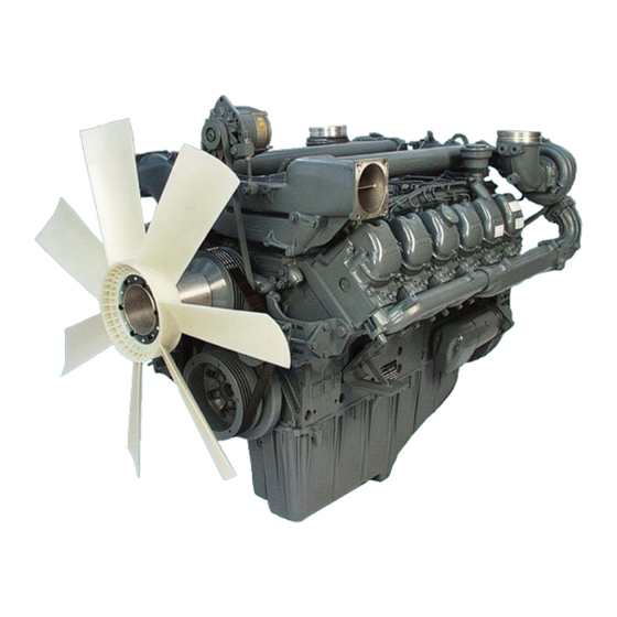
Page 18: Engine Views D 2848 Le 203
Engine views D 2848 LE 203 Front view of engine Rear view of engine... - Page 19 Engine views D 2848 LE 203 View of engine from right-hand side View of engine from left-hand side...
- Page 20 Engine views D 2848 LE 203 View of engine from above...
-
Page 21: Schematic Diagram Of Engine Lubrication System
Schematic diagram of engine lubrication system 1 Oil line to crankshaft 6 Oil pump with oil pressure relief valves 2 Injection pump lubrication 7 Bores for connecting rod bearing lubrication 3 Lube oil lines to turbochargers 8 Oil drain plug 4 Oil return line from turbochargers 9 Oil suction pipe 5 Bores for main bearing lubrication... - Page 22 Schematic diagram of engine lubrication system 1 Lube oil lines to turbochargers 7 Oil pressure relief valve 2 Rocker arm lubrication 8 Oil cooler 3 Gudgeon pin lubrication 9 Bypass valve 4 Spray nozzles for piston cooling and cam lubrication 10 Oil filter 5 Camshaft bearing lubrication 11 Oil galleries...
-
Page 23: Schematic Diagram Of Fuel System
Schematic diagram of fuel system 1 Fuel injector 5 Overflow valve 2 Fuel injection pump 6 Fuel tank 3 Electro-hydraulic shut-off (EHAB) 7 Fuel filter 4 Hand pump with prefilter 8 Fuel delivery pumps... -
Page 24: Schematic Diagram Of Cooling System
Schematic diagram of cooling system 1 Overflow and vent pipe 7 Filler pipe 2 Positive pressure / negative pressure valve 8 Thermostat 3 Coolant level in surge tank 9 Engine / crankcase 4 Surge tank 10 Water pump 5 Coolant filler neck 11 Fan 6 Degassing system 12 Radiator / intercooler... -
Page 25: Schematic Diagram Of Engine Control Unit
1 Injection pump drive gear 5 Crankshaft gear 2 PTO output gear / air compressor gear 6 Oil pump drive gear 3 Idler gear 7 Oil pump impeller gears 4 Camshaft drive gear... -
Page 26: Checking And Adjusting Start Of Fuel Delivery
Checking and adjusting start of fuel delivery Checking start of delivery Figs. 1 and 2 For the purpose of checking the start-of-delivery setting, an “OT” (= TDC) mark and a scale from 10 ... 50_ before TDC are engraved on a disc Á fitted in front of the torsional vibration damper. - Page 27 Checking and adjusting start of fuel delivery Fig. 5 Remove plug from inspection hole in timing case cover. Fig. 6 Then rotate engine so that mark on pointer fitted to injection pump coincides with mark on pump hub. Read degrees on scale engraved on disc on tor- sional vibration damper.
- Page 28 Checking and adjusting start of fuel delivery Fig. 9 Remove timing case cover. Note: Pipes are attached to the timing case cover. To facilitate reassembly, note down the positions of the brackets, pipe clamps, spacer sleeves etc. Fig. 10 Turn engine to specified angle for delivery start. Fig.
-
Page 29: Removing And Installing Injection Pump
Removing and installing injection pump Removing injection pump Note: The subsequent reinstallation of the injec- tion pump is rendered considerably easier if before its removal the engine has been turned to start of delivery. See page 24. Fig. 1 Remove the charge-air elbow and the charge-air pipes leading to the turbocharger. - Page 30 Removing and installing injection pump Fig. 5 Remove container together with fuel hand pump too. Fig. 6 Remove all fuel connections from injection pump. Remove oil return line from crankcase. Caution: The lines contain fuel. Catch emerging fuel in a container. Fig.
- Page 31 Removing and installing injection pump Fig. 9 Remove mounting bolts from injection pump. Take off injection pump. Note: Ensure meticulous cleanliness when work- ing on the injection pump. Prevent dirt and foreign matter from pene- trating into opened line connections. Installing injection pump Fig.
- Page 32 Removing and installing injection pump Fig. 13 Fit injection pump in such a way that the mounting bolts can be screwed in by hand. Check distance between injection pump and crank- case. Fig. 14 Tighten mounting bolts to specified torque (see “Service Data”).
-
Page 33: Removing And Installing Fuel Injectors
Removing and installing fuel injectors Removing fuel injectors Fig. 1 To facilitate removing the injection lines, remove the charge-air elbow and the charge-air pipes lead- ing to the turbocharger. Fig. 2 Remove the injection lines from the injection nozzles and from the injection pump. Remove the fuel return lines. - Page 34 Removing and installing fuel injectors Fig. 5 Screw adapter on to nozzle holder. Screw on inertia extractor and knock out nozzle holder. Take sealing ring off the injection nozzle. Check and repair injector, see page 33. Installing fuel injectors Fig. 6 Insert new sealing ring, apply “Never Seeze”...
-
Page 35: Checking And Repairing Fuel Injectors
Checking and repairing fuel injectors Checking fuel injectors Fig. 1 The nozzle tester (manual test stand) is used to check the − opening pressure − tightness − spray pattern of the injection nozzle. Use pure testing oil or pure Diesel fuel for the test. Prior to testing, clean nozzle and check it for wear, see page 34. - Page 36 Checking and repairing fuel injectors Disassembling fuel injectors Fig. 3 Insert injector assembly (the inlet orifice facing downwards) into the clamping device and hold in a vice. Remove union nut and take out nozzle body, inter- mediate washer, pressure pin, compression spring and shim.
- Page 37 Checking and repairing fuel injectors Fig. 7 Dip nozzle body and nozzle needle separately into filtered Diesel fuel and check their gliding quality. When pulled out of the nozzle body by up to a third of its length the nozzle needle must sink back to its seat under its own weight when released.
-
Page 38: Fuel Prefilter
Fuel prefilter Cleaning fuel prefilter Fig. 1 Disassemble fuel prefilter: D Remove filter housing (arrow) Fig. 2 D Wash out filter housing À and gauze filter Á in clean Diesel fuel and blow them out with com- pressed air D Reassemble using new seal D Screw on filter housing and tighten it to 10−12 Nm Fig. -
Page 39: Removing And Attaching Fuel Filter, Exchanging Filter Cartridge
Removing and attaching fuel filter, exchanging filter cartridge Removing and attaching fuel filter Fig. 1 Remove the fuel lines À. Remove the mounting bolts Á and take off fuel filter. Attachment is to be carried out in reverse se- quence. The fuel lines are to be fitted with new sealing rings. - Page 40 Removing and attaching fuel filter, exchanging filter cartridge Bleeding the fuel system Note: To bleed the fuel system switch on the “ignition” so that the EHAB will be open. Figs. 4 and 5 An arrow on the filter head indicates the direction of fuel flow.
-
Page 41: Flame-Starter Sheathed-Element Glow Plug, Removing And Installing
Flame-starter sheathed-element glow plug, removing and installing Removing sheathed-element glow plug Fig. 1 Disconnect the electric connections from the sheathed-element glow plug. Remove fuel line carefully. Loosen counter nut on sheathed-element glow plug and remove glow plug. Installing sheathed-element glow plug Fig. -
Page 42: Draining And Filling With Coolant
Draining and filling with coolant Draining coolant Danger: Draining hot coolant involves a risk of scal- ding. Drain coolant as follows when cooling system has cooled down: Caution: Drain coolant into a suitable container and dispose of it in accordance with regula- tions. - Page 43 See Publication “Fuels, Lubricants and Coolants for MAN Diesel Engines”. Coolant must be added at the filler neck only. Ensure that the ratio of water to anti-freeze is cor- rect.
-
Page 44: Removing And Installing Thermostat Insert
Removing and installing thermostat insert Fig. 1 D Drain coolant, see page 40 Remove the three mounting bolts from the coolant neck and take off coolant neck. Fig. 2 Take out short-circuit inserts / thermostats. Check the function of the thermostat insert as follows: D Hang thermostat in a pot filled with water D Heat water... -
Page 45: Removing And Installing Engine Water Pump
Removing and installing engine water pump Removing engine water pump D Drain coolant, see page 40 D Remove the thermostats, see page 42 Fig. 1 Take V-belt off water pump, see page 120. Fig. 2 Remove coolant hose pipe leading to oil cooler. Fig. - Page 46 Removing and installing engine water pump Installing engine water pump Fig. 4 Clean the sealing faces on water pump and engine housing. Fit water pump with new seal. Fit the mounting bolts. Fig. 5 Turn engine to ignition TDC, see page 24. Set delivery start indicator so that its measuring edge points exactly to the TDC point on the grad- uated scale.
-
Page 47: Repairing Engine Water Pump
Repairing engine water pump Water pump for three thermostats Fig. 1 1 Pump housing 2 Impeller 3 Cap 4 Axial face seal 5 Water pump bearing 6 V-belt pulley / hub 7 Circlip Removing water pump, see page 43. Disassembling water pump Fig. - Page 48 Repairing engine water pump Fig. 5 Pull impeller off the pump bearing. For this purpose four threaded bores M8 are pro- vided. Fig. 6 Align water pump housing on a suitable and stable surface. Use a suitable mandrel to press the water pump shaft together with bearing out of the housing.
- Page 49 Repairing engine water pump Fig. 9 Turn water pump housing over. Press in new mechanical seal with press-fitting sleeve (special tool) until it stops. Observe installation note for seal on page 51. Note: The seal can be exchanged even without removing the water pump shaft.
- Page 50 Repairing engine water pump Fig. 13 If no suitable pressing tool is available, you may use self-made special tools (see chapter “Special tools”) and proceed as follows: D Align guide ring (2) with the two dowel pins on the pump housing D Insert pressing ring (1) into guide ring D Place a flat steel (min.
- Page 51 Pull off V-belt pulley with three-arm puller. Unclip the circlip from the water-pump housing. Fig. 16 Press impeller off the shaft, using a suitable man- drel. For this purpose align water pump housing horizontally on a stable support. The picture shows an assembly device for this.
- Page 52 Repairing engine water pump Fig. 18 Turn water pump housing over. Press in new mechanical seal with press-fitting sleeve (special tool) until it stops. Observe installation note for seal on page 51. Note: The seal can be exchanged even without removing the water pump shaft.
- Page 53 Install mechanical seal while “wet”, i.e. to install it, coat holding sleeve à and water pump shaft À with a mixture of either 50% water and 50% cleaning spirit or 40% to 50% antifreeze agent as per MAN 324 and water.
-
Page 54: Cleaning Cooling System
In such cases, the insects, dust etc. should be removed from the honeycomb system of the radia- tor block and the radiator itself then cleaned with the cleansing agent HENKEL P3-begesol. This cleansing agent is available from MAN in 10-kg cans under Part No. 09.21002-0164. Procedure:... - Page 55 Cleaning cooling system Removal of lime deposits in the cooling system Procedure: D Drain the coolant D Fill the system with undiluted original pickling fluid (Engine pickling fluid RB-06), see sources of supply D Let the engine run (also in normal operation) for approx. 8 hours with this filling in the cooling circuit D Drain the pickling fluid and thoroughly flush the system with tap water D If necessary, refill the circuit again with fresh pickling fluid and pickle the engine for another 8 hours D Drain the pickling fluid, fill the system with tap water, and run the engine at idle for 5 minutes to flush out...
-
Page 56: Changing Oil Filter
Changing oil filter Caution: Used oil and oil filters are classed as dan- gerous waste and must de disposed of ac- cordingly. Note instructions for preventing environmental damage. Fig. 1 Open oil drain plug on oil filter can and use con- tainer to catch oil that may emerge. -
Page 57: Removing And Installing Oil Cooler
Removing and installing oil cooler D Drain coolant, see page 40 D Remove oil filter, see page 54 Caution: Used oil and oil filter cartridges are dan- gerous waste. Observe safety regulations to prevent damage to the environment. Fig. 1 Remove oil filter head (5 bolts). - Page 58 Removing and installing, repairing oil pump Drain engine oil Danger: The oil is hot − risk of scalding. Do not touch the oil drain plug with bare fingers. Oil is an environmental hazard. Handle it with care! Figs. 1 and 2 With the engine at operating temperature, remove the oil drain plugs on the oil sump and the oil filter bowl and allow the old oil to drain off completely.
-
Page 59: Removing And Installing, Repairing Oil Pump
Removing and installing, repairing oil pump Fig. 5 Remove the mounting bolts from the overpressure valve and from the oil pump. Take off overpressure valve and oil pump. The overpressure valve is encapsulated. Opening pressures see “Service Data”. Note: Depending on the engine model and oil pan variant, various oil pump versions are possible. - Page 60 Removing and installing, repairing oil pump Fig. 9 Attach cover. Tighten the mounting bolts to the specified torque. Grind or exchange heavily worn covers. Checking axial play of the pump gears Fig. 10 Position dial gauge and push shaft up to the stop in one direction and set dial gauge to “0”.
- Page 61 Removing and installing, repairing oil pump Refilling with oil Caution: Do not add so much engine oil that the oil level rises above the max. marking on the dipstick. Overfilling will result in damage to the engine. Figs. 13 and 14 Refill with fresh engine oil at the oil filler neck (arrow).
-
Page 62: Oil Spray Nozzle
Oil spray nozzle Removing oil spray nozzle D Drain engine oil, see page 56 D Remove oil pan, see page 56 Fig. 1 Remove mounting bolts from oil spray nozzle (arrow). Take off oil spray nozzle with valve. Checking oil spray nozzle valve Fig. - Page 63 Oil spray nozzle Fig. 5 Check direction of oil jet. The oil jet from each nozzle must reach unhampered the inlet port of the cooling duct in the piston crown À and two cams Á. On no account must bent oil spray nozzles be re- adjusted.
-
Page 64: Removing And Installing Vibration Damper, Changing Front Crankshaft Seal
Removing and installing vibration damper, changing front crankshaft seal Removing vibration damper D Relax and remove V-belt, see page 120 D Turn engine to ignition TDC. This ensures that in subsequent assembly work the indicating dial will be in the correct position. Fig. - Page 65 Removing and installing vibration damper, changing front crankshaft seal Changing front crankshaft seal Fig. 5 Remove the mounting bolts from the cover. Fig. 6 Take off cover. Replace front crankshaft seal only as a complete unit, i.e. race and radial shaft seal. Replace race Fig.
- Page 66 Removing and installing vibration damper, changing front crankshaft seal Fig. 9 Special tools are required for installing the race. Clean inner side of race and crankshaft stub. Coat crankshaft stub with sealing agent “Antipor 46”. D Push race À and pressing sleeve Á onto adapter Å...
- Page 67 Removing and installing vibration damper, changing front crankshaft seal Installing vibration damper Fig. 13 Fit oil splash ring to crankshaft. Place vibration damper on two guide pins (M16 x 1.5). Ensure that the position of the graduated disc relative to the crankshaft is correct. Tighten mounting bolts to specified torque.
-
Page 68: Removing And Installing Flywheel, Replacing Gear Ring
Removing and installing flywheel, replacing gear ring Removing flywheel D Remove speed pickup, see page 127 Fig. 1 Loosen mounting bolts, securing the engine against turning if necessary. Fig. 2 Remove two bolts facing each other and replace them by two guide pins (special tool). Remove all bolts. - Page 69 Removing and installing flywheel, replacing gear ring Changing starter gear ring Fig. 5 Remove flywheel. Drill a hole in starter gear ring and snap it using a chisel. Caution: Take care not to damage the flywheel. Fig. 6 Note: Since the maximum axial runout (lateral runout) of the starter ring gear must not be exceeded, the axial runout of the flywheel is to be measured on the contact face of...
-
Page 70: Removing And Installing Crankshaft Seal (Flywheel End)
Removing and installing crankshaft seal (flywheel end) Removing crankshaft seal Fig. 1 Remove flywheel, see page 66. Use special tool or a screwdriver to prise out seal. Installing crankshaft seal Fig. 2 When fitting a new shaft seal, you should also ex- change the bearing race of the flywheel. -
Page 71: Exchanging Bearing Race
Pull off the bearing race to be exchanged using a puller (special tool). Fig. 2 Insert the new bearing race into the pressing man- drel (special tool) so that for the subsequent as- sembly the internally chamfered side faces the fly- wheel. -
Page 72: Crankshaft Seals
Crankshaft seals General remarks on crankshaft seals As a matter of fundamental principle only radial shaft seals made of polytetrafluor ethylene (PTFE), trade name Teflon, are used. PTFE seals can be easily distinguished from the former elastomer seals by their considerably wider and flat sealing lip which is no longer pre-loaded by means of a tubular spring. -
Page 73: Removing And Installing Intake Manifold
Removing and installing intake manifold Note: When carrying out work on the intake sys- tem, ensure meticulous cleanliness to pre- vent dirt and foreign matter from penetrat- ing into the system. Removing intake manifold Fig. 1 Remove the charge-air elbow and the charge-air pipes leading to the turbocharger. -
Page 74: Removing And Installing Exhaust Manifold
Removing and installing exhaust manifold Removing exhaust manifold D Remove turbocharger, see page 76 Fig. 1 Remove the guard plates. Fig. 2 Note: The exhaust-gas pipe can be removed with the exhaust manifold attached. Remove the mounting bolts from the exhaust pipe. Danger: The exhaust pipe is heavy. -
Page 75: Turbocharger, Trouble Shooting
Turbocharger, trouble shooting Before removing the turbocharger carry out the following checks Turbochargers are frequently exchanged if the oil consumption is too high, the output too low or the intake and / or exhaust gas noises appear to be abnormal. Subsequent inspections by the manufacturer of the supposedly defective parts frequently prove the turbo- chargers to be in order. - Page 76 − The engine is overfilled with oil D Check whether the correct dipstick and guide pipe combination is installed − The engine oil used is unsuitable (see publication “Fuels, Lubricants, Coolants for MAN Diesel Engines”) − The engine is being run on impermissibly steep inclines −...
-
Page 77: Checking The Charge-Air Pressure
Extreme operating conditions (full-load operation and high air temperature) and the use of unsuitable en- gine oils (also see publication “Fuels, Lubricants, Coolants for MAN Diesel Engines”) may cause deposits on the compressor as well as in the intercooler, which results in a reduction in charge-air pressure. -
Page 78: Removing And Installing Turbocharger
Removing and installing turbocharger Removing turbocharger Fig. 1 Remove the charge-air elbow and the charge-air pipes leading to the turbocharger. Fig. 2 Remove pipe leading to crankcase breather (arrow). Fig. 3 Detach intake neck. Fig. 4 Remove oil pressure line À and oil return line Á from turbocharger. - Page 79 Removing and installing turbocharger Fig. 5 Remove the bolts from the turbocharger. Take off turbocharger. Note: Ensure meticulous cleanliness when putt- ing the turbocharger aside to prevent dirt and foreign matter from penetrating into the interior of the turbocharger. Installing turbocharger Fig.
-
Page 80: Checking Axial And Radial Clearance Of Turbocharger Rotor Shaft
Checking axial and radial clearance of turbocharger rotor shaft D Remove turbocharger, see page 76 D Mark turbine housing relative to the bearing housing D Remove turbine housing Axial clearance Fig. 1 Apply dial gauge holder and dial gauge under pre- load to shaft end face of the turbine wheel as shown. -
Page 81: Removing And Installing Cylinder Head
Removing and installing cylinder head Removing the rocker arms and push rods Fig. 1 Take off the cylinder head covers. Caution: Residual amounts of oil may emerge du- ring this operation. Used oil is dangerous waste. Observe safety regulations to prevent da- mage to the environment. - Page 82 Removing and installing cylinder head Fig. 5 Take off cylinder head and cylinder head gasket. Check whether cylinder head sealing face and cyl- inder block are plane using a straight edge. Non-plane cylinder heads can be remilled 1 mm. Notice specified projection of injection nozzles and valve recess (see “Service Data”).
- Page 83 Removing and installing cylinder head Figs. 9 and 10 Tighten bolts by angle. Observe order of tightening and specified tighten- ing method, and see instructions and notes on the cylinder head bolts in the publication “Service Data”. Note: To avoid any distortion between cylinder heads and exhaust manifolds, we recom- mend proceeding as follows: D Place cylinder head gaskets and cyl-...
- Page 84 Removing and installing cylinder head General notes The sealing effect of the cylinder head gasket largely depends on whether the required initial tension for the cylinder head bolts is reached and maintained. Use calibrated torque wrenches to tighten the cylinder head bolts. When the specified final torque is applied it must be maintained for at least 5 seconds.
-
Page 85: Setting Valve Clearance
Setting valve clearance Adjust the valves only when engine is cold (max. coolant temperature 50°C). Fig. 1 Remove cylinder head cover. Caution: Residual amounts of oil may emerge du- ring this operation. Used oil is dangerous waste. Observe safety regulations to prevent da- mage to the environment. - Page 86 Setting valve clearance Fig. 5 D Push feeler gauge between valve stem and rocker arm D Loosen lock nut (17 mm) and turn adjusting screw with screwdriver until feeler gauge can be moved with slight resistance D Tighten lock nut to the specified torque D Check clearance again D Refit cylinder head covers with new gaskets.
-
Page 87: Removing And Installing Rocker Arms
Removing and installing rocker arms Fig. 1 Remove rocker arms, see page 79. Unclip circlip. Fig. 2 Take rocker arms off the rocker arm shaft. Note: If the rocker arm bearing bushes have to be exchanged, ready-to-install new or re- conditioned rocker arms are to be used. -
Page 88: Removing And Installing Valves
Removing and installing valves Removing valves Remove rocker arms. Take off cylinder head, see page 79. Fig. 1 Note: Valve spring and valve spring retainer can also be replaced with the cylinder head installed. For this purpose the relevant piston must be at TDC, and the valve assembly lever is required. - Page 89 Removing and installing valves Installing valves Fig. 5 Note: Minor damage to the valve seat can be eliminated by lapping using valve lapping paste. New valves must always be lapped until an even valve seat has been achieved. Machine valve seat insert if necessary. Turn cylinder head over and insert valve spring washers.
- Page 90 Removing and installing valves Fig. 9 Screw valve assembly lever on to cylinder head. Insert the valve spring washers. Insert discs and valve springs. The word “TOP” facing upwards, the tight coils facing downwards. Replace damaged or weak springs. Fig. 10 Compress the valve springs using assembly lever and insert the valve cone pieces.
-
Page 91: Removing And Installing Valve Guides
Removing and installing valve guides D Removing and installing cylinder head, see page 79 D Removing and installing valves, see page 86 Fig. 1 Press valve guide out of the combustion chamber side using pressing mandrel (special tool). Oil new valve guide and drive / press it into the cylinder head using pressing mandrel and spacer sleeve (special tool). -
Page 92: Cylinder Head
Replacing valve seat insert Removing valve seat insert Note: f the valve seat inserts have to be changed it is necessary to change the valve guides too, as otherwise exact refacing of the valve seat inserts after the replacement cannot be guaranteed. For these reasons previously mentioned the tool for removing and installing valve guides and valve seat inserts was also designed in such a way that if this tool is used valve seat inserts can be re- placed only together with the valve guides, i.e. -
Page 93: Replacing Valve Seat Insert
Replacing valve seat insert Installing valve seat insert Fig. 4 Cool new valve seat insert down to approx. -200°C and insert it into the cylinder head (at an ambient temperature of approx. 20°C). Carry out check by driving it in until the stop is re- ached using pressing tool. -
Page 94: Reworking Valve Seat
Reworking valve seat Reworking valve seat (with Mira precision valve seat machining device) Fig. 1 1 Driving crank 2 Toggle switch 3 Handle 4 Lubricating nipple 5 Mains connection 6 Magnetic flange with coil 7 Guide pipe 8 Slewing arm 9 Guide mandrel 10 Tool 11 Hex socket screw... - Page 95 Reworking valve seat Fig. 4 Release Jaccard lever, place magnetic flange flush on the clamping plate and set the height so that the tool does not contact the valve seat. Set toggle switch to position 1. Tighten the Jaccard lever. Fig.
- Page 96 Reworking valve seat Fig. 8 Note: When dressing the valve seat inserts, re- move as little material as possible from the seat face. The valve retrusion is to be used as refer- ence value. If the cylinder head interface is to be machined (max.
-
Page 97: Refacing Valves
Refacing valves Fig. 1 Apply abrasive paste to tapered area on the valve seat. Oil valve guide and insert valve. Fig. 2 Use valve refacer to reface valve seat by applying moderate axial pressure and describing a turning motion. Caution: Keep valve stem and valve guide free of abrasive paste. -
Page 98: Checking Compression Pressure
Checking compression pressure Fig. 1 D Check valve clearance and adjust, if necessary, see page 83 D Let engine run until coolant temperature re- aches approx. 60−80°C D Remove all fuel injectors, see page 31 D For compression guideline values, see publica- tion “Service Data”... -
Page 99: Removing And Installing Timing Case
Removing and installing timing case Removing timing case D Remove starter, see page 117 D Removing flywheel, see page 66 D Remove fuel filter, see page 37 D If necessary removing air compressor, see page 121 Fig. 1 Oil and coolant lines, brackets for cable harnesses etc are attached to the timing case;... - Page 100 Removing and installing timing case Fig. 5 Tighten bolts to specified torque. Tighten the mounting bolts of the oil pan. Remove seal residues from sealing face of timing case cover. Screw on timing case cover with new seal. Fit the oil and coolant lines. Refit all components previously removed.
-
Page 101: Removing And Installing Camshaft, Exchanging Camshaft Bearings
Removing and installing camshaft, exchanging camshaft bearings Removing camshaft D Drain coolant, see page 40 D Remove oilpan, see page 56 D Remove starter, see page 117 D Remove flywheel and timing case, see page 66 D Remove the rocker arms and take out the push rods, see page 79 Note: For removing the camshaft the engine must be turned by 180_. - Page 102 Removing and installing camshaft, exchanging camshaft bearings Installing camshaft Fig. 4 Oil and insert the push rods. Oil the camshaft bearing bushes. Apply oil to camshaft and insert it carefully. Caution: Ensure that the bearings do not get dama- ged. Fig.
- Page 103 Removing and installing camshaft, exchanging camshaft bearings Fig. 8 Use suitable lever to press camshaft up to stop on timing case. Push camshaft forwards against the dial gauge feeler until stop is reached. The dial gauge reading equals the camshaft axial play. Refit all removed parts.
-
Page 104: Checking Valve Timing
Checking valve timing Note: If the valve timing is incorrect, serious da- mage to the engine may result. For this reason, if faults occur in the en- gine which could lead to the shrunk-fitted camshaft gear turning, check that the gear is correctly seated by checking the valve timing. -
Page 105: Removing And Installing Crankshaft
Removing and installing crankshaft Removing crankshaft D Remove oil pan and oil pump, see page 56 D Remove timing case, see page 97 D Remove front cover with crankshaft seal, see page 62 Fig. 1 Remove the bolts from the connecting rod bearing covers and put the covers aside, arranging them in the sequence of installation. - Page 106 Removing and installing crankshaft Checking spread of bearing shells Fig. 5 Position bearing shells together on flat surface. Measure and note down spread dimensions “A” and “B”. Spread dimension = A−B Installing crankshaft Fig. 6 Clean oil ducts in crankcase and in crankshaft with dry compressed air.
- Page 107 Removing and installing crankshaft Checking axial clearance Fig. 9 Note: The axial clearance of the crankshaft de- pends on the crankshaft bearing at the fly- wheel end (thrust bearing). D Fit dial gauge holder with dial gauge to crank- case D Apply dial gauge tip to crankshaft D Move crankshaft in axial direction to and fro and read off clearance on dial gauge...
-
Page 108: Removing And Installing Piston With Connecting Rod
Removing and installing piston with connecting rod Removing piston with connecting rod D Drain engine oil, see page 56 D Removing cylinder head, see page 79 Fig. 1 Remove bolts from connecting rod bearing cap. Fig. 2 Take off connecting rod bearing caps with bearing shells, expediting the procedure by means of light strokes with a synthetic hammer if necessary. - Page 109 Removing and installing piston with connecting rod Installing piston with connecting rod Note: If the pistons must be changed, ascertain by measuring the pistons or reading the measurement on the top of the piston whether undersized pistons were installed. If this is the case, undersized pistons must be used.
- Page 110 Removing and installing piston with connecting rod Fig. 9 The arrow on the top of the piston must always point towards the engine centre, i.e. towards the injection pump. Fig. 10 Put connecting rod bearing caps in place. Caution: The numbers on the connecting rod bea- ring cap and connecting rod big end must be on one side.
-
Page 111: Removing Piston From And Attaching To Connecting Rod Checking - Changing Connecting Rod
Removing piston from and attaching to connecting rod checking - changing connecting rod Detaching piston from and attaching to connecting rod Fig. 1 Remove piston with connecting rod. Clamp connecting rod in a vice using soft jaws. Remove gudgeon pin circlip. Fig. - Page 112 Removing piston from and attaching to connecting rod checking - changing connecting rod Fig. 5 Clean connecting rod and inspect for external damage; scrap any defective rods. Check connecting rod to see whether the piston pin bore is parallel or twisted relative to the bearing shell bore.
-
Page 113: Removing, Installing And Changing Piston Rings
Removing, installing and changing piston rings Piston ring arrangement Fig. 1 1 Compression ring (double-sided keystone ring) 2 Compression ring (tapered compression ring) 3 Oil scraper ring (bevelled-edge ring) Removing piston rings Fig. 2 Remove piston with connecting rod. Clamp connecting rod in a vice using soft jaws. Adjust piston ring pliers to piston diameter. - Page 114 Removing, installing and changing piston rings Installing piston rings Figs. 5 and 6 Use piston ring pliers to place piston rings in the correct piston ring grooves (“TOP” mark facing up- wards). Checking piston ring axial clearance Fig. 7 Use feeler gauge to ascertain the piston ring clear- ance at several points in each groove.
-
Page 115: Replacing Cylinder Liners
Replacing cylinder liners Removing cylinder liners Note: Observe oversizes for cylinder liner outer diameters and collar heights (see “Service Data ”). D Remove cylinder head, see page 79 D Remove pistons, see page 106 Fig. 1 Mark cylinder liner position relative to engine so that it can be reinstalled in the same position if re- used. - Page 116 Replacing cylinder liners Fig. 5 Note: After fitting the cylinder liners ensure that the O-rings are in the correct position by checking the liner protrusion with special tool. Use special tool, see page 178, as follows: Position press-on measuring plate with turned collar facing the liner using 2 fitting sleeves to centre plate.
- Page 117 Replacing cylinder liners Fig. 9 Apply thin coat of engine oil to cylinder liner in the area of the upper and lower O-ring. Apply thin coat of engine oil to lower O-rings in the crankcase. Insert cylinder liners into crankcase and push them down by hand.
-
Page 118: Measuring Piston Protrusion
Measuring piston protrusion Measuring piston protrusion Fig. 1 Remove cylinder heads. Move piston to be measured to TDC. Apply dial gauge in holder to crankcase sealing face. Set dial gauge to “0”. Fig. 2 Carefully slew dial gauge holder round, lifting the dial gauge tip as you do so. -
Page 119: Removing And Installing Starter
Removing and installing starter Fig. 1 Disconnect minus cable from battery or switch off battery main switch if fitted. Disconnect cable from terminal 31 (minus terminal, thick cable), terminal 30 (plus terminal, thick cable) and terminal 50 from starter. Fig. 2 Remove mounting nuts. -
Page 120: Removing And Refitting Alternator
Removing and refitting alternator Removing alternator D Relax V-belt and take it off the alternator pulley, see page 120 D Disconnect earth cable from battery Fig. 1 Disconnect terminals B+, B− (55 A alternator only), D+ and W from alternator. Alternator −... -
Page 121: V-Belts
V-belts Checking condition Fig. 1 D Check V-belts for cracks, oil, overheating and wear D Change demaged V-belts Checking tension Fig. 2 Use V-belt tension tester to check V-belt tension. D Lower indicator arm À into the scale Fig. 3 D Apply tester to belt at a point midway between two pulleys so that edge of contact surface Á... - Page 122 V-belts Tensioning / exchanging V-belt Alternator − top-mounted Fig. 5 D Remove fixing bolts À D Remove lock-nut Á D Adjust nut  until V-belts have correct tensions D Retighten lock-nut and fixing bolts To replace the V-belts loosen lock-nut and swing alternator inwards.
-
Page 123: Removing And Refitting Air Compressor
Removing and refitting air compressor Removing air compressor Fig. 1 Remove fuel filter. Close cut-off valve from fuel tank to engine. Remove all fuel lines from fuel filter and take off fuel filter complete with EHAB. Caution: The filter cartridges contain fuel. When putting aside the filter, catch emerg- ing fuel in a suitable container. -
Page 124: Electronic Speed Control
An electronic control system consists of three components: 1. Speed pickup In MAN engines the speed pickup Á, which works according to the induction principle, is located on the flywheel housing. It consists of a permanent magnet surrounded by a coil. - Page 125 Electronic speed control Electric control unit The GAC ESD 5221 electronic speed governor is used as an example here to give a general overview of the possibilities provided by this control system and to show what characteristic data can be set or altered. When installing and commissioning, please heed without fail the Operator’s Manual for the respective con- trol unit model.
- Page 126 Electronic speed control 1 LED display for electronic overspeed control 2 Output contacts “Overspeed” LED display for overspeed 3 Overspeed reset button: initial position of the relay contacts after overspeed signal has been sent. Resetting can also be effected by briefly interrupting the battery power supply 4 Overspeed test button, lowers the switching point by approx.
-
Page 127: Troubleshooting With Gac Governor
Troubleshooting with GAC governor Fig. 1 The control unit is equipped with a terminal strip for the connections of the output and input signals. − Checking procedure: Engine does not BATTERY start. Fig. 2 Check battery voltage on control unit during start- ing procedure. - Page 128 Troubleshooting with GAC governor Fig. 5 ACTUATOR Check final controlling element. Remove both final controlling element cables from control unit and measure resistance. Correct value: 4,6 - 5 W If value deviates, check cabling and plug. If cabling and plug are in order, exchange final controlling element.
-
Page 129: Removing And Installing Speed Pickup
Removing and installing speed pickup Fig. 1 The speed pickup is fitted to the bottom right-hand side of the flywheel housing. To remove it, disconnect cable from terminal, re- move the mounting bolts from the retaining plate and take it off together with the speed pickup. Fig. -
Page 130: Overspeed Protection
Overspeed protection If an electronic speed governor is used, an over- speed protection independent of the governor must be provided. For this purpose an electromagnetic shut-off valve (EHAB) is installed in the fuel supply line to the injection pump. If the governor fails, this valve will shut off the fuel supply, thus preventing the engine from revving up in an uncontrolled manner. -
Page 131: Coolant Level Probe
Coolant level probe Monitoring the coolant level All engines are equipped with either one or two coolant level probes for monitoring the coolant level in the coolant expansion tank. This probe is of the capacitative type. The sensor and the evaluating electronics form a unit. -
Page 133: Service Data
Service Data... -
Page 134: Engine D 2848 Le 201 / 202 / 203 / 211 / 212 / 213
Specifications Engine D 2848 LE 201 / 202 / 203 / 211 / 212 / 213 Design ..........V 90_ Mode of operation . -
Page 135: Engine D 2840 Le 201 / 202 / 203 / 211 / 212 / 213
Specifications Engine D 2840 LE 201 / 202 / 203 / 211 / 212 / 213 Design ..........V 90_ Mode of operation . -
Page 136: Engine D 2842 Le 201 / 202 / 203 / 211 / 212 / 213
Specifications Engine D 2842 LE 201 / 202 / 203 / 211 / 212 / 213 Design ..........V 90_ Mode of operation . -
Page 137: Crankcase
Dimensions Service Data Limit values Crankcase Standard size: 153,90−154,00 mm (Ø 153,9 H9) for cylinder liners with 0,5 and 1,0 mm lar- ger outside diameter: 154,40−154,50 mm (Ø 154,4 H9) Ø Standard size: Ø 145,80−145,84 mm (Ø 145,8 H7) for cylinder liners with 0,5 mm larger out- side diameter: 146,30−146,34 mm (Ø... -
Page 138: Crankshaft
Dimensions Service Data Limit values Crankshaft Crankshaft front end (opposite end to flywheel) 99,985−100,020 mm (Ø 100 j7) standard size: 89.98−90.00 mm undersize −0.25: 89.73−89.75 mm undersize −0.50: 89.48−89.50 mm undersize −0,75: 89.23−89.25 mm undersize −1.00: 88,98−89,00 mm standard size: 103.98−104.00 mm undersize −0.25: 103.73−103.75 mm... - Page 139 Dimensions Service Data Limit values Crankshaft rear end (adjacent to flywheel) Max. permissible runout with crankshaft taken up in end bearings: D 2848 LE 2.. at bearing 3 0,06 mm D 2840 LE 2.. at bearing 3 and bearing 4 0,06 mm D 2842 LE 2..
- Page 140 Dimensions Service Data Limit values Alignment bearing standard size: 37.74−37.81 mm undersize −0.25: 38.24−38.31 mm undersize −0.50: 38.24−38.31 mm undersize −0.75: 38.74−38.81 mm undersize −1.00: 38,74−38,81 mm Spread: 0,1−0,5 mm Marking: top / bottom standard size: 0164 / 0165 mm undersize −0.25: 0168 / 0169 mm undersize −0.50:...
-
Page 141: Flywheel And Starter Gear Ring
Dimensions Service Data Limit values Flywheel and starter gear ring Ø Flywheel: 432,490−432,645 mm (Ø 432 u9) Internal gear ring Ø: 432,000−432,155 mm (Ø 432 H9) Interference: 0,335−0,645 mm Installation temperature: 200−230_C Ø Ø m = 65,1 kg (with gear ring) J = 1,975 kgm Number of teeth: Z = 160, module 3 Matching gear: Starter pinion (Z = 9) - Page 142 Dimensions Service Data Limit values Flywheel and starter gear ring Ø Flywheel: 432,490−432,645 mm (Ø 432 u9) Internal gear ring Ø: 432,000−432,155 mm (Ø 432 H9) Interference: 0,335−0,645 mm Installation temperature: 200−230_C Ø m = 60,554 kg (with gear ring) J = 2,392 kgm Number of teeth: Z = 160, module 3 Matching gear: Starter pinion (Z = 9)
- Page 143 Dimensions Service Data Limit values Flywheel and starter gear ring Ø Flywheel: 432,490−432,645 mm (Ø 432 u9) Internal gear ring Ø: 432,000−432,155 mm (Ø 432 H9) Interference: 0,335−0,645 mm Installation temperature: 200−230_C Ø m = 32,640 kg (with gear ring) J = 1,10 kgm Number of teeth: Z = 160, module 3 Matching gear: Starter pinion (Z = 9)
-
Page 144: Conrod
Dimensions Service Data Limit values Conrod up to engine No... 8628 999 ..46,055−46,065 mm Ø Bearing bore in measuring directions 1, 2 and 3 and in measuring planes a and b: 90,064−90,106 mm Pre−condition: New conrod bearing in place, conrod as- sembled 8 mm 8 mm... - Page 145 Dimensions Service Data Limit values Conrod from engine No... 8629 001 ..46,055−46,065 mm Bearing bore in measuring directions 1, 2 and 3 and in measuring planes a and b: 90,064−90,106 mm Pre−condition: New conrod bearing in place, conrod as- sembled 8 mm 8 mm...
- Page 146 Dimensions Service Data Limit values Conrod D 2848 / 40 / 42 LE 211 / 212 / 213 46,055−46,065 mm Bearing bore in measuring directions 1, 2 and 3 and in measuring planes a and b: 90,075−90,120 mm Edge condition: New conrod bearing in place, conrod as- 8 mm 8 mm...
-
Page 147: Piston
Dimensions Service Data Limit values Piston D 2848 LE 2.. up to engine No..8628 999..Compression height: 81,250−81,300 mm with undersize 0,2 mm: 81,050−81,100 mm 0,4 mm: 80,850−80,900 mm 0,6 mm: 80,650−80,700 mm Piston protrusion above crankcase top: 0,01−0,38 mm Ø... - Page 148 Dimensions Service Data Limit values Piston D 2840 / 42 LE 2.. up to engine No..8358 999..Compression height: 81,250−81,300 mm with undersize 0,2 mm: 81,050−81,100 mm 0,4 mm: 80,850−80,900 mm 0,6 mm: 80,650−80,700 mm Piston protrusion above crankcase top: 0,01−0,38 mm Ø...
- Page 149 Dimensions Service Data Limit values Piston D 2848 LE 2.. from engine No..8629001..D 2840 / 42 LE 2.. from engine No..8359 001..Compression height: 81,250−81,300 mm with undersize 0,2 mm: 81,050−81,100 mm 0,4 mm: 80,850−80,900 mm 0,6 mm: 80,650−80,700 mm Piston protrusion above crankcase top: Ø...
-
Page 150: Cylinder Head
Dimensions Service Data Limit values Cylinder head Ø 12,000−12,018 mm (Ø 12 H7) Ø 17,1−17,5 mm ö Intake valve ö = 60_ Exhaust valve b = 45_ a = 3,3−3,8 mm b = 3,3−3,8 mm Ø Valve guide bore in cylinder head: 18,000−18,018 mm (Ø... - Page 151 Dimensions Service Data Limit values Valves Ø Intake valve:11,969−11,980 mm Exhaust valve: 11,944−11,955 mm Max. wear limit: max. 0,1 mm Valve recess for intake and exhaust valve: 0,7−1,3 mm Valve springs Inner spring: Free length (L), approx. 65,5 mm Spring force at L46,3 mm: 128−152 N Spring force at L = 32,3 mm: 255−294 N Outer spring: Free length (L), approx.
-
Page 152: Valve Gear
Dimensions Service Data Limit values Valve gear Rocker arm bearing pedestal 24,967−24,980 mm (Ø 25 f6) Rocker arms Rocker arm radial clearance: 0,025−0,054 Wear limit: 0,08 mm 25,005−25,021 mm Camshaft Replace if there are traces of wear Camshaft axial clearance: 0,20−0,90 mm Wear limit: 1,5 mm 69,910−69,940 mm (Ø... - Page 153 Dimensions Service Data Limit values Valve tappets Bore in crankcase: 20,000−20,021 mm (Ø 20 H7) Ø 19,944−19,965 mm Valve clearance Valve clearance (cold engine) Intake valve: 0,5 mm Exhaust valve: 0,6 mm Valve timing 1 = engine direction of turn 2 = intake valve opens 24 °...
-
Page 154: Engine Lubrication
Dimensions Service Data Limit values Engine lubrication Valve opening pressures Bypass valve for oil filter 2−4 bar Single horizontal, 2−fold horizontal 2,8−3,6 bar 2−fold vertical, 2−fold vertical reversible 2,2−2,8 bar Overpressure valve on the oil pump 9−10 bar Pressure valve of the oil injection nozzles Opening pressure 1,6−1,9 bar Pressure at max. - Page 155 Dimensions Service Data Limit values Three-wheel oil pump for D 2842 LE 2.. Oil pump wheel 14,5−14,7 mm 28,927−28,960 mm (Ø 28 e8) Housing depth: 28,000−28,033 mm (Ø 28 H8) Axial clearance: 0,040−0,106 mm 33,911−33,950 mm (Ø 34 e8) Housing depth: 34,000−34,039 mm (Ø...
-
Page 156: Cooling System
Dimensions Service Data Limit values Cooling system Engine coolant pump D 2840 LE 2.. gap: 0,5−0,9 mm Ø impeller: 135−136 mm Bearing seat in housing: 54,940−54,970 mm (Ø 55 R7) Ø of bearing: 54,981−54,994 mm Interference: 0,011−0,054 mm Bore for bearing shaft in impeller: 16,000−16,018 mm (Ø... - Page 157 Dimensions Service Data Limit values Valve cover on expansion tank Valve cover with working valve (small co- ver) opens at 0,6 bar−0,7 bar overpressure, 0,02 bar−0,08 bar underpressure Valve cover with safety valve (for filler, big cover) opens at 0,85 bar−1,2 bar overpressure Thermostat Opening begins at: 79_C ("2_) Fully open: 94_C...
-
Page 158: Turbocharger
Dimensions Service Data Limit values Turbocharger Manufacturer D 2848 LE 201 / 202 / 203 K27−3267 MLCKA 21.22 D 2848 LE 211 / 212 / 213 − 1500 rpm K27−3369 QXAK 19.22 D 2848 LE 211 / 212 / 213 − 1800 rpm K27−3369 QXAK 19.22 D 2840 LE 201 / 202 −... -
Page 159: Fuel System
Dimensions Service Data Limit values Fuel system Injection nozzles D 2848 LE 201 / 202 / 203 Manufacturer Bosch Type of injector DLLA 144 P 581 Number of holes Opening pressure of injector New nozzle holder: 295 + 8 bar Used nozzle holder: 280 + 8 bar Nozzle holder... - Page 160 Dimensions Service Data Limit values Injection pumps and governors D 2848 LE 201 / 202 / 203 In−line injection pump: GAC governor PE 8 P120 A500 LS7891 Governor: GAC governor ACB 275 H D 2848 LE 211 / 212 / 213 In−line injection pump: GAC governor PE 8 P120 A500 LV...
- Page 161 Dimensions Service Data Limit values Start of delivery Model Start of delivery ± 1° crank angle before TDC (Speed constant = without injec- tion timing mechanism) with optimised with optimised consumption D 2848 LE 201 1500 rpm, constant 14° 10° 1800 rpm, constant 14°...
-
Page 162: Starter Motor
Dimensions Service Data Limit values Starter motor Manufacturer: Bosch Type: Operating method: splined shaft Starter motor pinion: Number of teeth: Z = 9 Module: Nominal power: 6,6 kW Nominal voltage: 24 V Alternator Manufacturer: Bosch Type: Design: 1−pole, insulated Operation: Threephase current Voltage: Max. -
Page 163: Torque Guide Values
Torque guide values Note: All screw connections whose purpose is not stated in the following table are to be tightened in accordance with the guide values in our company standard M 3059 (see page 163). Fit the bolts slightly oiled! Screw plugs DIN 908 M14x1,5, M16x1,5... - Page 164 Torque guide values Lubrication Oil cooler to oil filter head M8,8.8 ..........22 Nm Cover oil pump M8,8.8 .
- Page 165 Torque guide values Installation tightening torques according to company standard M 3059 Bolts / nuts with external or internal hexagon, head without collar or flange Thread size Property classes / tightening torques in Nm x pitch for 8.8 / 8 for 10.9 / 10 for 12.9 / 12 13,0...
- Page 166 Torque guide values Cylinder-head bolts General notes The engine may have either of the following two types of cylinder head bolt: D Cylinder head bolts with hex head tightened by the angle−of−rotation method, socket size 19 D Cylinder head bolts with Torx head tightened by the angle−of−rotation method, Torx wrench size E18 Bolts to be used in event of repairs: Bolts with hex head may be replaced by bolts with Torx head if all the bolts on the engine are to be chan-...
- Page 167 Torque guide values Retightening cylinder head bolts on new engines Engine cold or warm) Zweiter Nachzug der Zylinder- kopfschrauben erledigt The cylinder heads are fitted with cylinder-head bolts for rotation angle tightening. On new engi- nes, the cylinder-head bolts are retightened at the Second retightening of cylinder- factory after running in and marked by the sticker head-bolts completed...
- Page 168 Torque guide values Retightening the cylinder-head bolts following a repair (engine cold) Before inserting the cylinder-head bolts, apply Intake side / injection nozzle engine oil to the thread (not the threaded hole) and coat the seating surface of the bolt head with installation paste “Optimoly White T”.
- Page 169 Torque guide values Reuse of used cylinder-head bolts Check Before used cylinder-head bolts are reused, they must be checked as follows: Length With each tightening, the bolts are deliberately stressed beyond the stretch limit and each L = shaft length tightening thus extends their length permanently.
-
Page 170: Tightening Torque Values, Injection Pumps
Fixing Torque guide values Injection pump Tightening torque values, injection pumps D 2848 L.., D 2840 L.. Order of tightening: 1−2−3−4 in the steps: 1. initial torque: 10 Nm 2. initial torque: 50−55 Nm 3. final torque Bracket tightening method effective only if bolts of the strength class 8.8 (no more) are used. -
Page 171: Special Tools
Special tools... - Page 172 Special tools...
- Page 173 Special tools Fig. no. Designation Item number Test connection for compression recorder 80.99607−0002 V-belt tension indicator 80.99605−0267 Valve gauge 80.99607−0076 Valve setting spanner 83.09195−0002 Spanner for nuts on injection lines (17 mm) 80.99603−0025 Socket spanner set for fuel injector 4-groove 80.99603−0049 4-groove with fixing screw 80.99603−0121...
- Page 174 Special tools 12.2 12.1 14.1 15.6 15.7 15.4 15.3 15.1 15.3 15.5 15.1 15.2 18.1...
- Page 175 Special tools Fig. no. Designation Item number Puller for water pump pulley 80.99601−0037 Pressing mandrel for cassette seal in conjunction with handle 14.1 80.99617−0091 Driving mandrel for seal in timing case consisting of: 12.1 Guide sleeve 80.99604−0068 12.2 Pressing plate in conjunction with handle 14.1 80.99604−0069 Puller for front crankshaft bearing race 80.99601−0076...
- Page 176 Special tools 19.1 19.2 20.1 20.2 25.1 25.2 29.1 29.2...
- Page 177 Special tools Fig. no. Designation Item number Sleeves for valve stem seal 19.1 Insert sleeve for valve stem seal 80.99616−0004 19.2 Pressing sleeve for valve stem seal 80.99604−0005 Pressing tool for valve guide 20.1 Pressing mandrel for valve guide 80.99617−0013 20.2 Pressing rings in conjunction with 20.1 80.99616−0003...
- Page 178 Special tools...
- Page 179 Special tools Fig. no. Designation Item number Pressure gauge + accessories for charge-air pressure measurement 80.99605−0160 Dial gauge holder for measuring valve retrusion and piston protrusion 90.99605−0172 Valve assembly lever 80.99606−0031...
- Page 180 Special tools Fig. no. Designation Item number Measuring combination, consisting of: (1) Dial gauge 08.71000−1205 (2) Tracer pin for dial gauge 80.99605−0197 (3) Dial gauge holder 80.99605−0179 (4) Contact pin 80.99605−0180 (5) Dial gauge holder 80.99605−6006 (6) Dial gauge holder 80.99605−0172 Press-on measuring plate 80.99605−0195...
- Page 181 Special tools Pressing mandrel for cap, dia. 50.1 mm Pressing mandrel for cap, dia. 62.1 mm...
- Page 182 Special tools Special tools for water pump repair for local manufacture (Material: steel as available) Support ring for pressing out the water pump bearing Ø 68 Ø 56...
- Page 183 Special tools Special tools for water pump repair for local manufacture (Material: steel as available) Pressing ring for water pump cover Ø 153,8 − 154,2 Ø 137 Support ring for pressing in the water pump cover Ø 134 Ø 168...
-
Page 184: Index
Index Cylinder head covers ..... . Air compressor ......Cylinder head gaskets . - Page 185 Index Oil cooler, Removing and installing ... Thermostat ....... Oil pan .
Need help?
Do you have a question about the D 2848 LE 2 Series and is the answer not in the manual?
Questions and answers