Table of Contents
Advertisement
Quick Links
Antaira Technologies
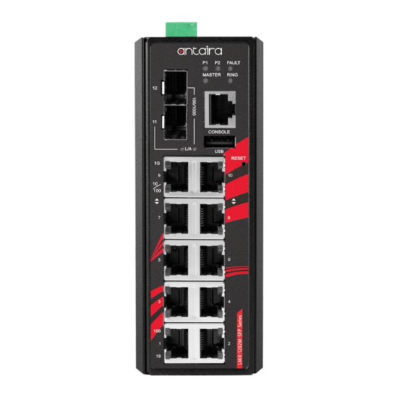
LMX-1202M-SFP Series
12-Port Industrial Managed Ethernet Switch, w/8*10/100Tx RJ45,
2*10/100/1000Tx RJ45, and 2*100/1000 SFP Slots, 12~48VDC
Power Input
Quick Installation Guide
Version 1.1
(November 2019)
Tel: 1-844-268-2472
Fax: 1-714-671-9944
www.antaira.com
Package Check List
The package contains the following items:
1 – Quick installation guide
1 – LMX-1202M-SFP(-T)
1 – Wall mounting bracket set with screws
1 – DC cable –18 AWG & DC jack 5.5 x 2.1mm
1 – RJ45 to DB9 Serial Console cable
1 – RJ45 dust cover set
Front Panel Layout
Grounding Screw
SFP# 11~12 – 100/1000 SFP
SFP# 11~12 – LED for Link/Activity Status
LAN# 9~10 – LED for Link/Activity Status
1000Mbps
LAN# 9~10 – LED for Link/Activity Status
10/100Mbps
LAN# 1~8 – LED for Link/Activity
Status 100Mbps
LAN# 1~8 – LED for Link/Activity
Status 10Mbps
Top Panel View
LMX-1202M-SFP series top panel is equipped with one 6-pin
removal terminal block connector for dual DC power inputs
(12~48VDC).
Product Overview
System Interface/Performance
All RJ45 ports support the auto MDI function
Embedded 8*10/100Tx RJ45, 2*10/100/1000Tx RJ45, and
2*100/1000 SFP Slots
Store-and-forward switching architecture
8K MAC address table
Power line EFT protection: 2,000VDC; Ethernet ESD
Protection: 6,000VDC
19020000000108
Power Input & Connection
Operating Temperature
Case/Installation
6-Pin Removal Terminal Block (Power Input)
LED Indicators
LED for Power 1, Power 2, Fault, Master,
and Ring
RJ45 for Serial Console RS232
USB2.0 – Configuration Backup Port
Reset Button
LAN# 9~10 – 10/100/1000Tx RJ45
LAN# 1~8 – 10/100Tx RJ45
LAN Port 1~8
(Upper LED)
6-Pin Removal Terminal Block (Power Input)
Grounding Screw
LAN Port 1~8
(Lower LED)
LAN Port 9~10
(Upper LED)
LAN Port 9~10
(Lower LED)
SFP Port
LINK/ACT
DC 12 to 48V redundant power with a 6-pin removal terminal
block
It is recommended to use a UL listed industrial power supply
Standard operating temperature model: -10°C to 70°C
Extended operating temperature model: -40°C to 75°C
IP30 protection
DIN-Rail and wall mount design
LED
Color
Description
On
Power input 1 is active
Power 1
Green
Off
Power input 1 is inactive
On
Power input 2 is active
Power 2
Green
Off
Power input 2 is inactive
Green
Preconfigured alarms are not detecting failure
Fault
Green/Red
Red
Preconfigured alarms are detecting failure
Flashing
Switch is in the process of booting
On
ERPS Owner Mode (Ring Master) is ready
Master
Green
Off
ERPS Owner Mode (Ring Master) is not active
On
Ring Network is active
Ring
Green
Off
Ring Network is not active
On
Connected to network, 100Mbps
Flashing
Networking is active
Green
Off
Not connected to network
On
Connected to network, 10Mbps
Flashing
Networking is active
Green
Off
Not connected to network
On
Connected to network, 1000Mbps
Flashing
Networking is active
Green
Off
Not connected to network
On
Connected to network, 10/100Mbps
Flashing
Networking is active
Green
Off
Not connected to network
On
Connected to network
Green:1000Mbps
11~12
/
Flashing
Networking is active
Amber:100Mbps
Off
Not connected to network
Advertisement
Table of Contents

Subscribe to Our Youtube Channel
Related Manuals for ANTAIRA LMX-1202M-SFP Series


Summary of Contents for ANTAIRA LMX-1202M-SFP Series
- Page 1 Ring Network is active Ring Green Top Panel View Ring Network is not active LMX-1202M-SFP series top panel is equipped with one 6-pin Connected to network, 100Mbps removal terminal block connector for dual DC power inputs LAN Port 1~8 Flashing Networking is active (12~48VDC).
- Page 2 (V1+, V1-) and PWR2 (V2+, V2-) contacts on the expense for shipping the RMA unit(s) to Antaira. Antaira is industrial Ethernet switch on the wall. terminal block connector as shown below in Figure 1.
Need help?
Do you have a question about the LMX-1202M-SFP Series and is the answer not in the manual?
Questions and answers