Johnson Controls Tyco HS2TCHPRO Installation Instructions Manual
Hide thumbs
Also See for Tyco HS2TCHPRO:
- User manual (140 pages) ,
- User manual (48 pages) ,
- User manual (54 pages)
Table of Contents
Advertisement
Quick Links
HS2TCHPRO/HS2TCHPROBLK
Installation Instructions
Warning: Please refer to the System Installation Manual for information on limitations regarding product use and
function and information on the limitations as to liability of the manufacturer. These instructions shall be used in con-
junction with the system Installation Manual of the Control Panel with which this equipment is intended to be used.
29010964R001
Advertisement
Table of Contents

Subscribe to Our Youtube Channel
Related Manuals for Johnson Controls Tyco HS2TCHPRO


Summary of Contents for Johnson Controls Tyco HS2TCHPRO
- Page 1 HS2TCHPRO/HS2TCHPROBLK Installation Instructions Warning: Please refer to the System Installation Manual for information on limitations regarding product use and function and information on the limitations as to liability of the manufacturer. These instructions shall be used in con- junction with the system Installation Manual of the Control Panel with which this equipment is intended to be used. 29010964R001...
-
Page 2: Table Of Contents
Contents Safety Instructions Installation Instructions Specifications Unpacking Mounting Wiring Basic Setup Setting the Keypad Language Enrolling the Keypad Keypad Display Symbols Proximity (Prox) Tags Support Assign Proximity Tags Delete Proximity Tags Function Key Assignment Available Function Key Options Programming Labels Optional Settings Enable/Disable Fire, Medical, Panic Buttons Extra Power Option... - Page 3 Approvals FCC Compliance Statement Industry Canada Compliance Statement Simplified Declaration of Conformity EN50131-1 Grade 3/Class II Limited Warranty SOFTWARE PRODUCT LICENSE - 3 -...
-
Page 4: Safety Instructions
Safety Instructions Read the safety information before you install the equipment. Important: This equipment must be installed by a skilled person only. A skilled person is an installer with appropriate technical training. The installer must be aware of potential hazards during installation and measures available to min- imize risks to the installer and other people. -
Page 5: Installation Instructions
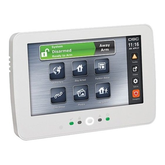
Installation Instructions Installation Instructions The HS2TCHPRO/HS2TCHPROBLK keypad can be used on security systems with up to 248 zones. These keypads are compatible with the PowerSeries Pro panel models HS3128, HS3032, HS3248. Specifications Temperature range: UL/ULC: 0°C to +49°C (32°F to 120°F); EN: -10°C to +55°C (14°F to 131°F) Weight: 405 g Humidity (MAX): 93% R.H. -
Page 6: Mounting
Mounting Mount the keypad near designated points of entry and exit. Once a dry and secure location is selected, do the fol- lowing: 1. If there is an SD card in the keypad, remove the SD card before opening the touchscreen. See Figure 1. Warning: Do not disassemble the touchscreen without removing the SD card first. -
Page 7: Wiring
Wiring Figure 2 - Mounting the Backplate Callout Description Mounting holes Wiring slot Hole for tamper screw Note: For ULC fire installations, the keypad must be mounted on top of an electrical box and used with conduit. 5. Run wire through wiring slot. Connect Corbus wiring to the keypad. See the Wiring section. 6. -
Page 8: Basic Setup
4. If the ‘P/Z’ terminal is programmed as an output, a small relay (such as DSC model RM-1 or RM-2), buzzer or other DC operated device may be connected between the positive supply voltage and the ‘P/Z’ terminal (max.load is 50mA). -
Page 9: Keypad Display Symbols
Basic Setup When this mode is selected, the total number of keypads currently enrolled is displayed. 1. Enter [902][000] to begin auto-enrollment of new keypads. Keypads are assigned to the next available slot. [902][001] Manual Enroll 1. Enter [902][001] or use the [<][>] keys and press [*]. 2. -
Page 10: Available Function Key Options
To program function keys 1,3,4,5: 1. On the keypad, press [*][8][Installer Code]. 2. Enter [861]-[892] to program keypads 1-32 respectively. 3. Enter [001-[005] for function keys 1-5 or use the [<][>] keys and press [*]. 4. Enter a 2-digit number to assign a function key operation - [00]-[68]. See Available Function Key Options below. -
Page 11: Optional Settings
Optional Settings 3. Enter the label name for the selected item. 4. Press Save when complete. Optional Settings The following settings are available through the Options menu. Enable/Disable Fire, Medical, Panic Buttons 1. Press Options, Installer Menu [Installer Code], Keypad Programming, then Options. 2. -
Page 12: Keypad Partition Assignment
[000] Keypad Partition Assignment Valid entries are 00-32. |___|___| [011] Keypad Input/Output Programming Zone or PGM Number Default 000 |___|___|___| [012] Local PGM Output Pulse Activation Time |___|___| Minutes (00-99) |___|___| Seconds (00-99) [021] First Keypad Options Default Value Option ON |__| Fire Key Enabled Fire Key Disabled... -
Page 13: Third Keypad Options
Keypad Programming Note: For UL/ULC installations, bit 5 (Power LED) and bit 6 (Power LED Indicates AC Present) shall be ON. [023] Third Keypad Options Default Value Option ON |__| Armed LED Power Save Armed LED Off in Sleep Mode |__| Keypad Status Shows Stay Arm Keypad Status Shows Stay/Away Arm |__|... -
Page 14: Reset Keypad Programming To Factory Defaults
04 Alarm tone (4 second duration) [991] Reset Keypad Programming to Factory Defaults 1. Press [*][8][Installer Code]. 2. Enter [991]. 3. Use the [<][>] keys to scroll to the applicable keypad. 4. Press [*] to select the keypad. 5. Re-enter [Installer Code]. 6. -
Page 15: Limited Warranty
Limited Warranty Note: For EN50131 compliant installations the following functions (initiated from the keypad emergency buttons) have to be disabled: Fire Alarm function Auxiliary (Medical) Alarm function Panic Alarm function Limited Warranty Digital Security Controls (DSC) warrants that for a period of 12 months from the date of purchase, the product shall be free of defects in materials and workmanship under normal use and that in fulfilment of any breach of such war- ranty, DSC shall, at its option, repair or replace the defective equipment upon return of the equipment to its repair depot. -
Page 16: Software Product License
SOFTWARE PRODUCT LICENSE The SOFTWARE PRODUCT is protected by copyright laws and international copyright treaties, as well as other intel- lectual property laws and treaties. The SOFTWARE PRODUCT is licensed, not sold. 1. GRANT OF LICENSE - This EULA grants You the following rights: (a) Software Installation and Use - For each license You acquire, You may have only one copy of the SOFTWARE PRODUCT installed. - Page 17 Limited Warranty 3. COPYRIGHT - All title and intellectual property rights in and to the SOFTWARE PRODUCT (including but not limited to any images, photographs, and text incorporated into the SOFTWARE PRODUCT), the accompanying printed mater- ials, and any copies of the SOFTWARE PRODUCT, are owned by DSC or its suppliers. You may not copy the printed materials accompanying the SOFTWARE PRODUCT.
- Page 18 DSC website. Please visit http://www.dsc.com/open-source-documentation for detailed information. © 2020 Johnson Controls. All rights reserved. JOHNSON CONTROLS, TYCO and DSC are trademarks of Johnson Con- trols. • www.dsc.com •...
Need help?
Do you have a question about the Tyco HS2TCHPRO and is the answer not in the manual?
Questions and answers