Table of Contents

Subscribe to Our Youtube Channel
Related Manuals for Johnson Controls CIW01


Summary of Contents for Johnson Controls CIW01
- Page 1 Operation Manual Model: CIW01 FLTR Meeting Room MODE SPEED LOUV. TEMP COOL LOUV. Adj. Menu On/Off Back/Help ECO IMPORTANT: READ AND UNDERSTAND THIS MANUAL BEFORE USING THIS WIRED CONTROLLER. KEEP THIS MANUAL FOR FUTURE REFERENCE. P5415479...
-
Page 3: Table Of Contents
TABLE OF CONTENTS 1. Safety Summary ..............................1 2. Switch Names and Functions ..........................4 3. Operation Method ............................5 3.1 Basic Procedures ............................5 3.2 Operation Mode (Cooling, Heating, Dry, Cooling/Heating Automatic and Air Flow Operation) ....5 3.3 Automatic Cooling/Heating Operation .....................6 4. Setting Method ..............................7 4.1 Temperature Setting ..........................7 4.2 Fan Speed ...............................7 4.3 Louver Swing Direction ...........................8... - Page 4 9. Help Menu ..............................39 9.1 Help Menu .............................39 9.2 Current Setting Display ........................39 9.3 Indicators on LCD ..........................40 9.4 About Operation ...........................41 9.5 Troubleshooting ............................41 9.6 Contact Information ..........................42 10. Other Indications ............................42 10.1 In Normal Condition ..........................42 10.1.1 Main/Sub Controller ........................42 10.1.2 Central Control ..........................43 10.1.3 Priorities ............................43 10.1.4 External Power Saving Control Processing .................43...
-
Page 5: Safety Summary
● Use only Johnson Controls recommended, provided as standardized, or replacement parts. ● Johnson Controls will not assume any liability for injuries or damage caused by not following steps outlined or described in this manual. Unauthorized modifi cations to Johnson Controls products are prohibited as they…... - Page 6 Shielded cable must be used in all areas to reduce the potential for communication errors. When shielded cabling is applied, proper bonding and termination of the cable shield is required as per Johnson Controls guidelines. Plenum and riser ratings for communication cables must be considered per application and local code requirements.
- Page 7 ● Be sure to install circuit breakers (ground fault interrupter, isolating switch, molded case circuit breaker, and so forth) with the specifi ed capacity. Ensure that the wiring terminals are tightened securely to recommended torque specifi cations. ● Clamp electrical wires securely with a cord clamp after all wiring is connected to the terminal block. In addition, run wires securely through the wiring access channel.
-
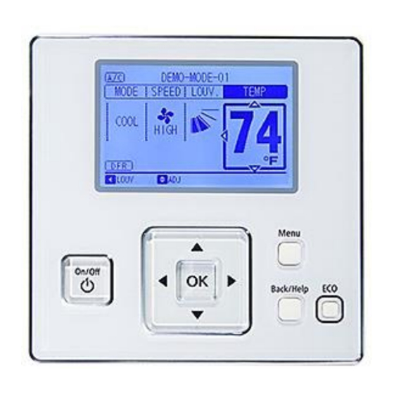
Page 8: Switch Names And Functions
2. Switch Names and Functions The fi gure below shows all the functions for reference. The actual display during operation is different. Display Part Fan Speed Indicator Room Name Louver Swing Schedule Timer Indicator Indicator Indicator Page 7) It is displayed when the schedule timer function is set. -
Page 9: Operation Method
3. Operation Method <Before Operation> Basic Procedures (1) Function Selection Apply power to the outdoor unit(s) at least By pressing “ ”or “ ”, the icon “ ” moves 12 hours prior to operation of the system for to the next function in order of the functions preheating of the compressor oil. -
Page 10: Automatic Cooling/Heating Operation
Automatic Cooling/Heating Operation In case dual setpoint is selected in automatic cooling/heating operation, *during auto mode both cooling setpoint and heating setpoint can be selected. By default, temperature when the cooling/heating mode changes as follows. Cooling mode changes to heating mode when the indoor temperature is heating setpoint -2°F (-1°C). -
Page 11: Setting Method
4. Setting Method Fan Speed (1) Press “ ” or “ ” and select “SPEED”. Temperature Setting (1) Press “ ” or “ ” and select “TEMP”. Menu Menu Back/Help Back/Help (2) By pressing “ ” or “ ”, the fan speed changes as follows. (2) By pressing “... -
Page 12: Louver Swing Direction
Louver Swing Direction 5. Operation (1) Press “ ” (On/Off). Operation Start Make sure that the power is ON. Press “ ” Press “ ” (On/Off). or “ ” and select “LOUV.”. The run indicator turns on and the operation starts. Menu Back/Help On/Off... -
Page 13: Power Saving Guidance
(1) To set the operation lock, press “ ” and (2) The current setting status is displayed for “Back/Help” simultaneously for 3 seconds. “Power Save Mode”, “Sav ON/OFF”, “Sav Level and Schedule”. It is possible to change The icon “ ” shows the lock is turned ON. When pressing “... -
Page 14: Menu Operation
(3) Press “ ” or “ ” and select the setting 8. Menu Operation function. By pressing “OK”, each type of Menu setting is displayed. • Every function setting is displayed in the “Menu”. Refer to the following concerning each setting. -
Page 15: Simple Timer Operation
Simple Timer Operation (4) Press “OK” to fi nish the “Simple Timer” setting. The confi rmation screen is • This function is used to start or stop the unit displayed. operation at the set time. Simple Timer 15:10(Fri) • The timer operation contents can be set from Menu “Not Used”, “Once”... -
Page 16: Reset Filter Sign Time
Reset Filter Sign Time Scheduled Operation This function is used to turn off the fi lter sign 8.4.1 Schedule Setting indication and to reset the time of use for the fi lter. • This function is used to start or stop the unit operation at a set time. - Page 17 (3) Select the day of the week (from Mon. to (5) Press “OK”. Sun.) by pressing “ ” or “ ”. The confi rmation screen is displayed. Press “OK”. • “ ” (run) and “ ” (stop) is displayed on the Timer Setting (Mon) 15:10(Fri) LCD.
-
Page 18: Holiday Setting
8.4.2 Holiday Setting (4) Press “OK” after the setting is completed. The confi rmation screen is displayed. • This function is used to deactivate the schedule operation temporarily for just one day. After that, the schedule operation recovers Holiday Setting 15:10(Fri) Menu automatically. -
Page 19: Schedule On/Off Setting
8.4.3 Schedule ON/OFF Setting Elevating Grille This function is not used. • This function is used to deactivate the scheduled operation temporarily. • The scheduled operation is not carried out when “OFF” is set in this function. • This function is used for long periods of time. (1) Select “Operation Schedule”... -
Page 20: Power Saving
(2) Select “Power Saving Mode Setting” by Power Saving pressing “ ” or “ ” and press “OK”. Function The “Power Saving Mode Setting” screen is 1. Outdoor Unit Capacity Control: displayed. “Peak cut mode” and “Moderate mode” are provided. Refer to 8.6.1. Controls the COOL/ Menu HEAT capacity of the outdoor unit. -
Page 21: Power Saving Detailed Setting (Outdoor Unit Capacity Control)
8.6.1 Power Saving Detailed Setting (2) Select “Detailed Setting” by pressing “ ” or “ ” and press “OK”. (Outdoor Unit Capacity Control) The power saving “Detailed Setting” screen This function is used to set the detail of the is displayed. outdoor unit capacity control. - Page 22 (5) Press “ ” or “ ” and select setting content. • If “Control Method” is selected, it changes as follows : “Peak Cut Control” ↔ “Moderate Control”. • If “Sav LOW (MED or HIGH)” is selected, it changes as follows : “100%”...
-
Page 23: Power Saving Detailed Setting (Indoor Unit Rotation Control)
8.6.2 Power Saving Detailed Setting (1) Select “Power Saving Setting” from the menu screen and press “OK”. (Indoor Unit Rotation Control) Regarding displayed item, refer to Menu “7. Power Saving Guidance”. This function sets the data of the indoor unit Menu 15:10(Fri) Back/Help... -
Page 24: Power Saving Detailed Setting (Intermittent Operation Control)
(5) Press “ ”or “ ” and select the setting 8.6.3 Power Saving Detailed Setting content. (Intermittent Operation Control) • If “Control Method” is selected, it changes This function is used to set details of the as follows: Intermittent Operation Control. “Address Order”... - Page 25 (2) Select “Detailed Setting” with “ ” or “ ” and (5) The setting confi rmation screen is displayed. press “OK”. Select “Yes” with “ ” or “ ” and press “OK” to confi rm the setting. The screen returns to •...
-
Page 26: Night Quiet Operation
Night Quiet Operation (3) The setting confi rmation screen is displayed. Select “Yes” with “ ” or “ ” and press “OK” This function is used to control the operation noise to confi rm the setting. The screen returns to of the outdoor unit. -
Page 27: Quick Function
Quick Function (3) The setting confi rmation screen is displayed. Select “Yes” with “ ” or “ ” and press “OK” This function operates for 30 minutes once the to confi rm the setting. The screen returns to operation starts. normal mode. -
Page 28: Comfort Setting
Comfort Setting (3) The setting confi rmation screen is displayed. Select “Yes” with “ ” or “ ” and press “OK” This function is used to control discharge or supply to confi rm the setting. The screen returns to air temperature when in the cooling mode. normal mode. -
Page 29: Power Saving/Operation Noise Reduction Schedule
8.10 Power Saving/Operation Noise (1) Select “Sav/Reduction Schedule” from the “Menu” screen and press “OK”. Reduction Schedule The power saving/operation noise reduction This function is used to start or stop the power schedule setting screen is displayed as “Sav/ saving or the noise reduction at the desired time. Reduction Schedule”. - Page 30 (4) Select the day set with “ ” or “ ” and (6) The setting confi rmation screen is displayed. press “OK”. The “Time Setting” screen is Select “Yes” with “ ” or “ ” and press “OK” displayed. to confi rm schedule setting. The screen returns to normal mode.
- Page 31 ■ Schedule ON/OFF Setting (3) Select “Schedule ON/OFF” with “ ” or “ ” and press “OK”. • This function is used to temporarily deactivate the schedule operation. Menu • Schedule control cannot be performed when the schedule setting is not accessible. Capacity Control 15:10(Fri) Back/Help...
-
Page 32: Individual Louver Setting
8.11 Individual Louver Setting (3) Select the indoor unit to change the louver direction by pressing “ ”, “ ”, “ ” or “ ”. 8.11.1 Setting Press “OK”. This setting is available only for indoor units that allow an individual louver control. Each louver Individual Louver Setting angle can be set individually. -
Page 33: Cancellation Of Louver Setting
8.11.2 Cancellation of Louver Setting 8.12 Louver Open/Close (1) Select “Individual Louver Setting” from the This function is unnecessary to set. “Menu” and press “OK”. Menu 15:10(Fri) 8.13 Ventilation Individual Louver Setting Louver Open/Close This function is unnecessary to set. VENTI Total Heat Exchanger SET Function 15... -
Page 34: Adjusting Date/Time
8.15 Adjusting Date/Time (3) Press “ ” or “ ” to change the setting. Press or keep pressing “ ” or “ ” to adjust • This function is used to adjust the date and time. numbers. • Revise time setting periodically and adjust if (4) After the setting is completed, press “OK”. -
Page 35: Daylight Saving Time
8.16 Daylight Saving Time ■ Stop Daylight Saving Time This function adjusts time forward or backward (1) Select “Daylight Saving Time” from the an hour when daylight saving time starts or ends. “Menu” screen and press “OK”. Menu (1) Select “Daylight Saving Time” from the “Menu”... -
Page 36: Setback Setting
8.17 Setback Setting (3) Press “ ” or “ ” to select setting contents. 8.17.1 Setback Schedule Setting The time goes 30 minutes ahead or behind. • This function is used to start/stop Setback mode Long press “ ” or “ ”... -
Page 37: Setback Manual Setting
8.18 Screen Display Setting 8.17.2 Setback Manual Setting • This function is used to temporarily activate 8.18.1 Display Adjustment Setback operation. Function • This function is available only when Setback • Time Format: mode is set as Manual mode. Changes the time form to 12 hour or 24 hour. •... -
Page 38: Language Setting
8.18.2 Language Setting (4) Press “ ” or “ ” and set the display. This function changes the displayed language. Time Format: The time format changes as follows: (1) Select “Screen Display Setting” from the 12 Hour ↔ 24 Hour “Menu”... -
Page 39: Temperature Unit
8.18.3 Temperature Unit (4) Press “ ” or “ ” and select setting data. • If “Temperature Unit” is selected (1) Select “Screen Display Setting” from the it changes as follows : “Menu” screen and press “OK”. “Degrees C” ↔ “Degrees F”. •... -
Page 40: Main/Sub Remote Controller
8.18.4 Main/Sub Remote Controller (4) The setting confi rmation screen is displayed. Select “Yes” with “ ” or “ ” and press “OK” This function is used to select Display/Non- to confi rm the setting. display for “MAIN” or “SUB” displayed on the The screen returns to normal mode. -
Page 41: Power Consumption Display
(2) By pressing “Back/Help”, letter and symbol 8.20 Power Consumption Display types can be changed. This function displays the power consumption of the outdoor unit compressor. Room Name Registration The value of each displayed in Graph/List format Menu is 1 day (24h (- every 2 hrs.)), 1 week (7 days), £... - Page 42 (2) The confi rmation screen is displayed. Display Scale Press “OK” to change the screen to “Power Change the scale using “ ” or “ ”. Consumption” display. Menu Back/Help Menu Back/Help Graph ↔ List Display Press “ECO” to change the “Power Consumption”...
-
Page 43: Help Menu
9. Help Menu Current Setting Display This function displays the setting content of the Help Menu operating condition of the air conditioning and The explanation of indicators on the LCD and controller. operations can be found in the “Help Menu”. The purpose of the “Help”... -
Page 44: Indicators On Lcd
Indicators on LCD List of indications for the “Current Setting” This function is used for explaining each icon on ON/OFF the LCD. Operation Mode Each Type Fan Speed (1) Select “About Indication” from the “Help Setting 1 Menu” and press “OK”. Explanations of Louver indicators on the LCD are displayed. -
Page 45: About Operation
About Operation Troubleshooting This function is used to explain operations and This function is used to troubleshoot operating operation methods. problems. Make sure that the troubleshooting section is read carefully before requesting repairs. (1) Select “About Operation” from the “Help Menu”... -
Page 46: Contact Information
Contact Information 10. Other Indications The screen displays “Contact Information” and the 10.1 In Normal Condition latest alarm code. 10.1.1 Main / Sub Controller (1) Select “Contact Information” from the “Help The icon “MAIN” is displayed as ON when the Menu”... -
Page 47: Central Control
10.1.2 Central Control 10.1.4 External Power Saving Control Processing When remote control operation is restricted (all functions) During Outdoor Capacity Control setting in process of the central controller or outdoor unit The central control “ ” turns ON. The icon “Ext. Sav” is displayed as ON. If the remote control restriction is set from the central controller, the settings for “RUN”, However, if the controller is set for indoor unit... -
Page 48: Operation Restriction
10.1.6 Operation Restriction Power Activation Setback Operation The icon “Preheating” is displayed as ON. In case the setback operation is enabled The compressor starts preheating. and the card key is removed, setpoint is Because the unit cannot operate beyond 4 compensated and fan operate at “Low”... -
Page 49: In Alarm Condition
10.2 In Alarm Condition 10.2.2 Power Failure • All the indications are OFF. 10.2.1 Alarm • Once the unit is stopped by power failure for longer than 2 seconds, the unit is not started • The RUN indicator (red) fl ashes. again although power recovers. - Page 52 © 2017 Johnson Controls, Inc. P5415479-rev.4 Code No. LIT-12013123 Issued September, 2019...
Need help?
Do you have a question about the CIW01 and is the answer not in the manual?
Questions and answers