Table of Contents
Advertisement
Quick Links
Advertisement
Table of Contents

Related Manuals for Rohm TO-263-7L


Summary of Contents for Rohm TO-263-7L
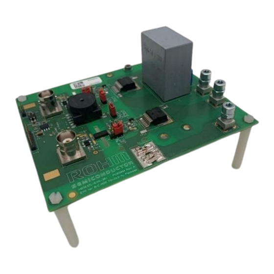
- Page 1 Generation SiC MOSFET (TO-263-7L) Half Bridge Evaluation Board User’s Guide...
- Page 2 [8] Be sure to wear insulated gloves when handling is required during operation. After Use [9] The ROHM Evaluation Board contains the circuits which store the high voltage. Since it stores the charges even after the connected power circuits are cut, please discharge the electricity after using it, and please deal with it after confirming such electric discharge.
- Page 3 The evaluation board provided here has only been subjected to functional testing under typical load conditions. The design of this evaluation board is tested by ROHM only as described in the user guide for this board. The design is not qualified in terms of safety requirements, manufacturing and operation over the entire operating temperature range or lifetime.
-
Page 4: Table Of Contents
Mounting Heatsink ..............................13 Starting up the board and tests ............................14 4.1. Evaluation board set up for various tests ........................14 Schematic and BOM ................................17 PCB Layout ..................................20 © 2022 ROHM Co., Ltd. No. 65UG002E Rev.001 4/23 Apr. 2022... -
Page 5: Safety Precautions
Failure to do so may cause personal injury. Caution: Incorrect connection of power supplies or loads can damage the board. Carefully review the information in this document. © 2022 ROHM Co., Ltd. No. 65UG002E Rev.001 5/23... -
Page 6: Introduction
Evaluate the switching characteristics with different gate resistors and gate drive voltages Continuous power testing in buck, boost or inverter configuration to evaluate the thermal performance of the SiC MOSFETs 3. Key Features Figure 2: Block diagram of evaluation board © 2022 ROHM Co., Ltd. No. 65UG002E Rev.001 6/23 Apr. 2022... -
Page 7: Connector Assignments
There are a total of 6 connectors on the evaluation board. Figure 4 shows the picture of connectors CO1 and CO2 with the respective pin assignments. Figure 3: Pin assignment of CO1 (left) and CO2 (right) © 2022 ROHM Co., Ltd. No. 65UG002E Rev.001 7/23... -
Page 8: Led Indications
LEDs “HS Supply” and LS Supply” lights up. Figure 5 shows the location of these LEDs. It must be noted that the board is functional only if all these three LEDs are lit. © 2022 ROHM Co., Ltd. No. 65UG002E Rev.001 8/23 Apr. -
Page 9: Isolated Power Supply And Setting The Gate Drive Voltage
A simple open loop control has been implemented for the isolated power supply generation. Hence to adjust the positive drive voltage the input supply on the CO1 has to be adjusted accordingly. The recommended gate source voltage of ROHM SiC MOSFET SCT4036KW is 15-18V. However, driving with 18V proves to be more efficient. - Page 10 The user must decide the appropriate turn-on/turn-off drive voltages and then adjust the input supply at connector CO1 and accordingly place jumpers J2-J4. Figure 7: Top view of the board with the jumper locations for adjusting turn off gate drive voltage © 2022 ROHM Co., Ltd. No. 65UG002E Rev.001 10/23...
-
Page 11: Setting The Gate Resistors
A total of 10 test points has been provided on this board to monitor the important signals during the electrical characterization process of the SiC MOSFETs. Table 1 shows the list of the test points and their purpose. © 2022 ROHM Co., Ltd. No. 65UG002E Rev.001 11/23 Apr. -
Page 12: Device Current Measurement
1.7mm. Figure 10 depicts the usage of a Rogowski coil for current measurements. For device current measurement using Rogowski coil, it is mandatory to short the jumper J1. © 2022 ROHM Co., Ltd. No. 65UG002E Rev.001 12/23 Apr. - Page 13 DUT source, care must be taken to use appropriate DC power supply and load that will support this. Figure 10: Current measurement set up with a co-axial shunt © 2022 ROHM Co., Ltd. No. 65UG002E Rev.001 13/23...
-
Page 14: Mounting Heatsink
Figure 11: Board bottom view with exposed copper and filled/capped vias (top left), thermal interface material with heatsink (top right), Mounting holes for heatsink (bottom left), evaluation board mounted with heatsink (bottom right) © 2022 ROHM Co., Ltd. No. 65UG002E Rev.001 14/23 Apr. -
Page 15: Starting Up The Board And Tests
Figure 12 shows the setup of the board for characterization of low side SiC MOSFETs. Figure 12: Double pulse test set up for low side device characterization © 2022 ROHM Co., Ltd. No. 65UG002E Rev.001 15/23 Apr. - Page 16 Figures 14, 15 and 16 show the setup and connection required for a synchro- nous buck, synchronous boost and 2-level inverter respectively. Figure 14: Synchronous Buck Converter test set up Figure 15: Synchronous Boost Converter test set up © 2022 ROHM Co., Ltd. No. 65UG002E Rev.001 16/23 Apr. 2022...
- Page 17 SiC MOSFET Figure 17 shows the efficiency measurements in buck operation of SiC MOSFETs SCT4036KW7 and SCT4062KW7 with this evaluation board. Figure 17: Efficiency Measurement in Buck operation © 2022 ROHM Co., Ltd. No. 65UG002E Rev.001 17/23 Apr. 2022...
-
Page 18: Schematic And Bom
HB2637L-EVK-301 User’s Guide 5. Schematic and BOM Figure 18: Schematic of the Power Supply Circuit © 2022 ROHM Co., Ltd. No. 65UG002E Rev.001 18/23 Apr. 2022... - Page 19 HB2637L-EVK-301 User’s Guide Figure 19: Schematic of the Power Stage © 2022 ROHM Co., Ltd. No. 65UG002E Rev.001 19/23 Apr. 2022...
- Page 20 Open choice CM Filter and Trafo Common mode filter ACM4520-142-2P-T000 Gate drive transformer 1:1.2:1.2 Vacuum- T60403-F5046-X100 schmelze Not mounted C19, C20, C27, Not placed/not mounted (n.p) C28, C33, C34, R4, © 2022 ROHM Co., Ltd. No. 65UG002E Rev.001 20/23 Apr. 2022...
-
Page 21: Pcb Layout
HB2637L-EVK-301 User’s Guide 6. PCB Layout Figure 20: Top Layer Figure 21: Inner Layer1 © 2022 ROHM Co., Ltd. No. 65UG002E Rev.001 21/23 Apr. 2022... - Page 22 HB2637L-EVK-301 User’s Guide Figure 22: Inner Layer2 Figure 23: Bottom Layer © 2022 ROHM Co., Ltd. No. 65UG002E Rev.001 22/23 Apr. 2022...
- Page 23 HB2637L-EVK-301 User’s Guide Figure 24: Silkscreen Top Figure 25: Silkscreen Bottom © 2022 ROHM Co., Ltd. No. 65UG002E Rev.001 23/23 Apr. 2022...
- Page 24 Products. ROHM does not grant you, explicitly or implicitly, any license to use or exercise intellectual property or other rights held by ROHM or any other parties. ROHM shall have no responsibility whatsoever for any dispute arising out of the use of such technical information.
Need help?
Do you have a question about the TO-263-7L and is the answer not in the manual?
Questions and answers