Table of Contents
Advertisement
Quick Links
UM11762
NTS0304EUK-ARD evaluation board
Rev. 1.0 — 27 May 2022
Document information
Information
Content
Keywords
NTS0304EUK, I
Arduino port, EVK
Abstract
The NTS0304EUK-ARD evaluation board is a daughterboard equipped
with an Arduino port, designated for easy test and design of NTS0304E
IC, 4-bit dual supply translating transceiver, with open drain, and auto
direction sensing. The board is fully compliant with IMXRT1050 EVK,
LPCXpresso55S69 (LPC55S69-ECK) and i.MX 8M Mini LPDDR4 EVK
(8MMINILPD4-EVK, 8MMINID4-EVK), including GUI software control. The
board can be attached to any device equipped with an Arduino port.
2
C-bus, level translator, bidirectional, auto direction sensing,
User manual
Advertisement
Table of Contents

Subscribe to Our Youtube Channel
Related Manuals for NXP Semiconductors NTS0304EUK-ARD


Summary of Contents for NXP Semiconductors NTS0304EUK-ARD
- Page 1 C-bus, level translator, bidirectional, auto direction sensing, Arduino port, EVK Abstract The NTS0304EUK-ARD evaluation board is a daughterboard equipped with an Arduino port, designated for easy test and design of NTS0304E IC, 4-bit dual supply translating transceiver, with open drain, and auto direction sensing.
- Page 2 UM11762 NXP Semiconductors NTS0304EUK-ARD evaluation board Revision history Date Description v.1.0 20220527 Initial version UM11762 All information provided in this document is subject to legal disclaimers. © NXP B.V. 2022. All rights reserved. User manual Rev. 1.0 — 27 May 2022...
- Page 3 UM11762 NXP Semiconductors NTS0304EUK-ARD evaluation board IMPORTANT NOTICE For engineering development or evaluation purposes only NXP provides the product under the following conditions: This evaluation kit is for use of ENGINEERING DEVELOPMENT OR EVALUATION PURPOSES ONLY. It is provided as a sample IC pre- soldered to a printed-circuit board to make it easier to access inputs, outputs and supply terminals.
-
Page 4: Introduction
(including original Arduino Uno R3) EVK / motherboards with the purpose of testing and measuring the characteristics of the NTS0304E Device Under Test (DUT). The NTS0304EUK-ARD daughterboard allows the ability to test and measure the static and dynamic characteristics of the DUT by accessing a digital potentiometer with SPI and C interface. -
Page 5: Assumptions
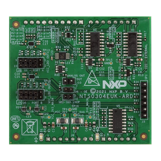
• Compliant with i.MX Mini LPDDR4 EVK board, including GUI (Windows 10) Note: For i.MX Mini LPDDR4 EVK Board it is necessary to use IMX8MMINI-IARD interposer board between the EVK and NTS0304EUK-ARD daughterboard (see IMX8MMINI-IARD User Manual). 4.2 Kit featured components Figure 1 identifies the main components on the board. -
Page 6: Block Diagram
UM11762 NXP Semiconductors NTS0304EUK-ARD evaluation board Figure 1. The NTS0304EUK-ARD board picture, top view (up) and bottom view (down) 4.3 Block diagram Figure 2 shows the block diagram of the NTS0304EUK-ARD daughterboard. The DUT is the NTS0304E IC (U6). The signal lines of the 4-bit level translator (the DUT) are connected to the circuit through the jumper headers J8 (PORT A), and J9 (PORT B). -
Page 7: Schematic Diagram
LDOs if the condition VCCA > VCCB occurs. For more details regarding power configuration, see the NTS0304E datasheet. Figure 2. NTS0304EUK-ARD block diagram 4.4 Schematic diagram The schematic diagram of NTS0304EUK-ARD is available at URL: http://www.nxp.com/ NTS0304E-ARD. 4.5 Arduino port... - Page 8 UM11762 NXP Semiconductors NTS0304EUK-ARD evaluation board Table 1. Arduino connectors pin chart and usage Ref Des Arduino label NTS0304EUK-ARD net Not used IOREF Not used RESET Not used 3.3V Power supply (3.3V) J6 (Power) Power supply (5V) Power supply return Power supply return...
-
Page 9: Level Translator
UM11762 NXP Semiconductors NTS0304EUK-ARD evaluation board Figure 3. NTS0304EUK-ARD – Arduino connectors 4.6 Level translator From the Arduino interface, the SPI and I C-bus are connected to PORT B of the 4-bit level translator U7. The are six total bus lines, therefore the SDA / SCL lines of the I bus are multiplexed with MOSI / SCLK of SPI bus. -
Page 10: Digital Potentiometer
UM11762 NXP Semiconductors NTS0304EUK-ARD evaluation board Figure 4. NTS0304EUK-ARD – Level translator 4.7 Digital potentiometer The signal lines from PORT B of level translators U8 and U10 are connected to the digital interface of U11 (Figure 5). The digital potentiometer AD5161 (U11) can be controlled through both SPI and I C-bus. -
Page 11: Spi / I2C External Connector
U9. The buffer output is available at analog out connector J10. Through the MUX U5, the analog out goes to input A0 of the Arduino interface. Figure 5. NTS0304EUK-ARD – Digital potentiometer 4.8 SPI / I C external connector The SPI / I C-bus lines can be accessed externally through connector J3. -
Page 12: Programmable Power Supplies Ldo1 And Ldo2
Figure 6. NTS0304EUK-ARD – SPI / I C-bus external connector 4.9 Programmable power supplies LDO1 and LDO2 NTS0304EUK-ARD contains two programmable power supplies: LDO1 and LDO2. Figure 7 depicts the LDO section of the schematic diagram. LDO1 provides the power for VCC_LDOUT1, and LDO2 supplies VCC_LDOUT2 power rail. Both regulators are controlled from the EVK through the Arduino port. -
Page 13: Ldo1
UM11762 NXP Semiconductors NTS0304EUK-ARD evaluation board Figure 7. NTS0304EUK-ARD – LDO section 4.9.1 LDO1 The programmable power supply LDO1 consists of an adjustable voltage regulator LDK120M (U3) and the analog switch 74HCT4052D (U1). The analog switch selects the resistor divider ratio in the feedback loop of the voltage regulator (U3). -
Page 14: Ldo2
The board contains four jumpers and several test points. Table 5 Figure 8 details the jumper locations and their default configurations. Table 6 describes the test points located on the NTS0304EUK-ARD board. Table 5. NTS0304EUK-ARD jumpers Ref Des Label Default Description ON – SPI chain loop closed OFF –... - Page 15 OFF - PORT A (U6) disconnected 1-2 / 3-4 / 5-6 / 7-8 – PORT B (U6) connected 1-2 / 3-4 / 5-6 / 7-8 OFF - PORT B (U6) disconnected Figure 8. NTS0304EUK-ARD Jumper locations Table 6. NTS0304EUK-ARD test points Ref Des Label Description...
-
Page 16: Installing And Configuring Software Tools
Ground Installing and configuring software tools NTS0304EUK-ARD evaluation board is designed and built as a daughterboard working in conjunction with an Arduino port equipped motherboard. The board was built to be fully compatible with the following NXP Evaluation (EVK) boards: •... - Page 17 J1 jumper shall be placed in position 5-6. If using an external power supply (connected to J2), the jumper J1 will be placed in position 1-2. 2. Insert the NTS0304EUK-ARD daughterboard on the Arduino connector of the EVK (see Figure 3.
-
Page 18: Lpcxpresso55S69 Development Board
UM11762 NXP Semiconductors NTS0304EUK-ARD evaluation board Figure 10. The assembly NTS0304EUK-ARD daughterboard / IMXRT1050 EVK board operation 6.2 Using the NTS0304EUK-ARD with an LPCXpresso55S69 development board Figure 11 shows the required hardware for operation of the NTS0304EUK-ARD and LPCXpresso55S69 EVK board. This configuration consists of: •... - Page 19 The following steps describe how to assemble, program, and operate the configuration shown in Figure 1. Insert the NTS0304EUK-ARD daughterboard to P16 – P19 connectors located on LPCXpresso55S69 development board (see the marked pins of P16 – P19, Figure 2. Connect the development board using port P6 USB port of PC 3.
-
Page 20: Using The Nts0304Euk-Ard With An I.mx 8M Mini Lpddr4 Evk Board
6.3 Using the NTS0304EUK-ARD with an i.MX 8M Mini LPDDR4 EVK board When an i.MX 8M Mini LPDDR4 EVK board is used with the NTS0304EUK-ARD board, a third board (IMX8MMINI-IARD interposer board) must be used, especially designed and built as an EVK – daughterboard interconnection. The EVK board i.MX 8M Mini LPDDR4 is not equipped with an Arduino port;... - Page 21 8MMINILPDDR4-EVK user manual and IMX8MMINI-IARD User Manual. The files can be downloaded from www.nxp.com/. Figure 13. The assembly NTS0304EUK-ARD daughterboard, IMX8MMINI-IARD interposer board, and i.MX 8M Mini LPDDR4 EVK, before starting To configure and operate the setup, follow the below steps: 1.
-
Page 22: Using Nts0304Euk-Ard With Another Device
EVK. Assure for correct electrical connections and avoid data conflicts on the signal lines, to prevent IC damage. GUI description A GUI application is available for the three EVK boards from NXP Semiconductors. The application is common for all three EVKs described in Section This section describes the GUI application and how the user can control the NTS0304EUK-ARD daughterboard from the graphical interface. - Page 23 UM11762 NXP Semiconductors NTS0304EUK-ARD evaluation board Figure 15. Graphical interface at start-up (“SETTINGS” tab activated by default) The GUI application starts with SETTINGS tab (marked with red arrow). The center of the window displays the board settings. The section provides the following settings: •...
- Page 24 UM11762 NXP Semiconductors NTS0304EUK-ARD evaluation board Figure 16. Graphical interface – “Dynamic” tab activated The second tab is DYNAMIC. Clicking on this new tab, a new window appears (see Figure 16). In the upper side of the window, from Set VCCA and Set VCCB drop-down lists, the user can select the power supply voltages.
-
Page 25: Abbreviations
UM11762 NXP Semiconductors NTS0304EUK-ARD evaluation board Figure 17. Graphical interface – “Static” tab activated The third tab is STATIC. Click on this tab and a new window appears (see Figure 17). The upper part of the display shows the same settings for Set VCCA and Set VCCB as in DYNAMIC tab. -
Page 26: References
NTS0304EUK-ARD evaluation board References 1. NTS0304E, 4-bit dual supply translating transceiver; open drain; auto direction sensing Product data sheet; NXP Semiconductors 2. MIMXRT1050-EVKB Board Hardware User’s Guide User manual; NXP Semiconductors 3. i.MX RT1050 Crossover Processors Data Sheet for Consumer Products Data sheet;... -
Page 27: Legal Information
NXP Semiconductors. In the event that customer uses the product for design-in and use in In no event shall NXP Semiconductors be liable for any indirect, incidental, automotive applications to automotive specifications and standards, punitive, special or consequential damages (including - without limitation - customer (a) shall use the product without NXP Semiconductors’... - Page 28 (up) and bottom view (down) ....6 LPCXpresso55S69 mother board, before Fig. 2. NTS0304EUK-ARD block diagram ....7 starting .............19 Fig. 3. NTS0304EUK-ARD – Arduino connectors ..9 Fig. 12. NTS0304EUK-ARD daughterboard / Fig. 4. NTS0304EUK-ARD – Level translator .....10 LPCXpresso55S69 motherboard operation ..20 Fig.
-
Page 29: Table Of Contents
Using the NTS0304EUK-ARD with an IMXRT1050 EVK board ........16 Using the NTS0304EUK-ARD with an LPCXpresso55S69 development board ...18 Using the NTS0304EUK-ARD with an i.MX 8M Mini LPDDR4 EVK board ......20 Using NTS0304EUK-ARD with another device ...............22 GUI description ..........22 Abbreviations ............
Need help?
Do you have a question about the NTS0304EUK-ARD and is the answer not in the manual?
Questions and answers