Table of Contents
Advertisement
Quick Links
UM11597
PCF2131-ARD evaluation board
Rev. 1.0 — 15 September 2021
Document information
Information
Content
Keywords
PCF2131, I
header, EVK
Abstract
The PCF2131-ARD evaluation board is a daughtercard equipped with Arduino
port and Aardvark header, for easy test and design of PCF2131TF IC. The
board is fully compliant with IMXRT1050 EVK, LPCXpresso55S69 and i.MX
8M Mini LPDDR4 EVK, including GUI software control.
2
C-bus, SPI-bus, Real Time Clock, RTC, Arduino port, Aardvark
User manual
Advertisement
Table of Contents

Related Manuals for NXP Semiconductors PCF2131-ARD


Summary of Contents for NXP Semiconductors PCF2131-ARD
- Page 1 C-bus, SPI-bus, Real Time Clock, RTC, Arduino port, Aardvark header, EVK Abstract The PCF2131-ARD evaluation board is a daughtercard equipped with Arduino port and Aardvark header, for easy test and design of PCF2131TF IC. The board is fully compliant with IMXRT1050 EVK, LPCXpresso55S69 and i.MX...
- Page 2 UM11597 NXP Semiconductors PCF2131-ARD evaluation board Revision history Date Description 20210915 Initial version UM11597 All information provided in this document is subject to legal disclaimers. © NXP B.V. 2021. All rights reserved. User manual Rev. 1.0 — 15 September 2021...
- Page 3 UM11597 NXP Semiconductors PCF2131-ARD evaluation board IMPORTANT NOTICE For engineering development or evaluation purposes only NXP provides the product under the following conditions: This evaluation kit is for use of ENGINEERING DEVELOPMENT OR EVALUATION PURPOSES ONLY. It is provided as a sample IC pre- soldered to a printed-circuit board to make it easier to access inputs, outputs and supply terminals.
-
Page 4: Introduction
C-bus or SPI-bus, a backup battery switch-over circuit, a programmable watchdog function, four timestamps function, and other features. For more details see the PCF2131TF datasheet. The PCF2131-ARD works as a daughtercard which can be connected through an Arduino port to various Arduino compatible (including original Arduino UNO R3) boards. -
Page 5: Assumptions
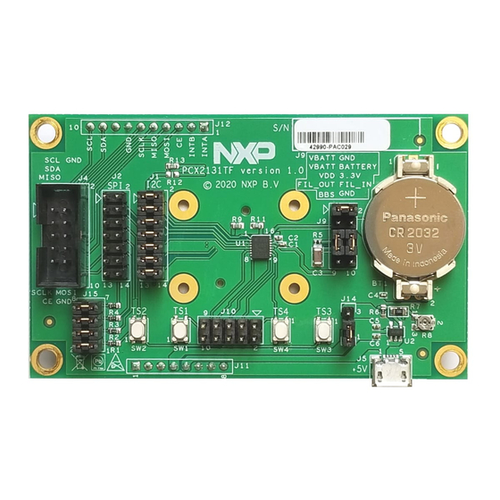
• Compliant with i.MX Mini LPDDR4 EVK board, including GUI (Windows 10) Note: For i.MX Mini LPDDR4 EVK Board it is necessary to use an IMX8MMINI-IARD interposer board between the EVK and PCF2131-ARD daughterboard (see UM11612 IMX8MMINI-IARD User Manual). 4.2 Kit featured components Figure 1 identifies the main components on the board. -
Page 6: Schematic, Board Layout And Bill Of Materials
Figure 1. Evaluation board featured component location, top view (up) and bottom view (down) 4.3 Schematic, board layout and bill of materials The schematic, board layout and bill of materials for the PCF2131-ARD evaluation board are available at http://www.nxp.com/PCF2131-ARD. 4.4 Arduino port... - Page 7 UM11597 NXP Semiconductors PCF2131-ARD evaluation board line used on this connector). See Table 1 for the connector pin chart, and the lines used in the circuit. Table 1. Pin chart of Arduino connectors Ref Des Arduino label PCF2131-ARD function Not used...
-
Page 8: I2C/Spi Bus Selection
PCF2131 JUMPER(OPTION1) = 1-2, 3-4, 5-6, 7-8, 9-10: ON - SPI-bus active aaa-043564 Figure 2. PCF2131-ARD daughterboard, I C/SPI bus jumper selection Note that interface selection should be done before the battery is supplied to VBAT pin. Once VBAT pin is powered, interface type can’t be changed even with the jumpers moved from I C locations to SPI locations, or vice versa. -
Page 9: Aardvark Header
I2C_SDA SPI_MISO SPI_SCK SPI_MOSI SPI_CE The PCF2131-ARD daughtercard contains a dedicated header (J4) for direct connection with an Aardvark I C/SPI Host Adapter. Table 3 depicts the pin chart of the Aardvark header. For more details, see the Aardvark I C / SPI Host Adapter from Total Phase (www.totalphase.com). -
Page 10: Power Supply
VBBS PCFVDD PCFVDD PCFBAT VBAT 0.1uF 0.1uF aaa-043565 Figure 3. PCF2131-ARD daughterboard, time stamp section 4.8 Power supply Figure 4 represents the J9 section of the PCF2131-ARD schematic diagram. 330 OHM VDD_3V3 VBBS VBBS PCFVDD PCFVDD PCFBAT HU2032-LF HDR 2X5 47uF 0.1uF... - Page 11 VDD_3V3 R/C FILTER PCF2131 aaa-043567 Figure 5. PCF2131-ARD daughterboard, pullup resistors detail To prevent the dongle from back powering the EVM, the following should be performed by the user (see Figure • The interface dongle should be plugged into the EVM after PCX2131TF or EVM is powered up.
-
Page 12: Installing And Configuring Software Tools
Installing and configuring software tools PCF2131-ARD evaluation board is designed and built as a daughterboard able to work in conjunction with a motherboard equipped with an Arduino port. The board is fully compatible with the following NXP Evaluation (EVK) boards: •... -
Page 13: Using Pcf2131-Ard With Imxrt1050 Evk Board
Figure 7. PCF2131-ARD daughterboard, initial hardware setup 6.1.1 Using PCF2131-ARD with IMXRT1050 EVK board Figure 8 shows the required hardware for operation of the PCF2131-ARD daughterboard with IMXRT1050 EVK. The following items are necessary: • One IMXRT1050-EVK board • One PCF2131-ARD daughterboard •... - Page 14 J1 jumper is placed in position 5-6. If using an external power supply (connected to J2), the jumper J1 is placed in position 1-2. • Insert the PCF2131-ARD daughtercard on the Arduino connector of the EVK (see Figure • Using USB connector J28, connect the EVK board to a USB port of the computer.
-
Page 15: Using Pcf2131-Ard With Lpcxpresso55S69 Development Board
Figure 9. PCF2131-ARD daughterboard / IMXXRT1050 EVK board, during operation 6.1.2 Using PCF2131-ARD with LPCXpresso55S69 development board Figure 10 shows the required hardware for operation of the PCF2131-ARD and LPCXpresso55S69 EVK board. This configuration consists of: • One LPCXpresso55S69 EVK board •... - Page 16 The following steps describe the hardware assembly operations, powering up, programming and operating the setup assembly: • Insert the PCF2131-ARD daughtercard to P16 – P19 connectors located on LPCXpresso55S69 development board (see the marked pins of P16 – P19, Figure UM11597 All information provided in this document is subject to legal disclaimers.
- Page 17 UM11597 NXP Semiconductors PCF2131-ARD evaluation board • Connect the development board using port P10 USB port of PC • Install the LPCXpresso55S69 target firmware (please download from NXP site and read the EVK_Firmware_And_GUI_Install_Guide_For_Arduino_Boards.pdf instruction file) • Install GUI application on PC (see the same instruction file) •...
- Page 18 UM11597 NXP Semiconductors PCF2131-ARD evaluation board Figure 11. PCF2131-ARD daughterboard / LPCXpresso55S69 motherboard operation UM11597 All information provided in this document is subject to legal disclaimers. © NXP B.V. 2021. All rights reserved. User manual Rev. 1.0 — 15 September 2021...
-
Page 19: Using Pcf2131-Ard With I.mx 8M Mini Lpddr4 Evk Board
PCF2131-ARD evaluation board 6.1.3 Using PCF2131-ARD with i.MX 8M Mini LPDDR4 EVK board When an i.MX 8M Mini LPDDR4 EVK board is used with the PCF2131-ARD board, a third board (IMX8MMINI-IARD interposer board) must be used, designed and built as an EVK – daughterboard interconnection. The EVK board i.MX 8M Mini LPDDR4 is not equipped with an Arduino port;... - Page 20 8M Mini LPDDR4 EVK, before getting to start To configure and operate the setup: 1. Insert the PCF2131-ARD onto the IMX8MMINI-IARD interposer board Arduino connectors (located on the top side) 2. Attach IMXMMINI-IARD connector plug J1 (located on the bottom of the board) into J1003 expansion board located on the top side of i.MX 8M Mini LPDDR4 EVK (see...
-
Page 21: Using Pcf2131-Ard With Another Arduino Device
Arduino port, and an EVK without an Arduino port. In the first case, a firmware shall be developed according with PCF2131TF specifications, and then simply attach PCF2131-ARD daughterboard to the EVK, to operate the board. In the second case, using the pin chart of Arduino connectors... -
Page 22: Gui Description
This section describes the GUI application for the three mentioned EVKs and how the user can control the PCF2131-ARD daughterboard from the graphical interface. First, install the GUI package and software on the PC (Windows 10). For more details, see UM11581. - Page 23 UM11597 NXP Semiconductors PCF2131-ARD evaluation board Clear Log button. A status bar located in the bottom side of the interface shows in real time the status connection between PC and the EVK. Figure 15. Graphical interface at start-up (“Settings” tab activated by default)
- Page 24 UM11597 NXP Semiconductors PCF2131-ARD evaluation board Figure 16. Graphical interface – “Registers” tab activated Figure 17 shows the graphical interface when Date/Time is activated. From this tab the user can set the date and the time of the RTC. The information is displayed in the upper blue section of the window.
- Page 25 UM11597 NXP Semiconductors PCF2131-ARD evaluation board The next tab is Alarm. The interface of this tab is shown in Figure 18. From here the alarm corresponding registers can be managed. See the PCF2131 datasheet to see more details regarding the alarm function and register map of the DUT IC. Note that...
- Page 26 UM11597 NXP Semiconductors PCF2131-ARD evaluation board Figure 19. Graphical interface – “Timestamp” tab activated Figure 20. Graphical interface – “ Watchdog Timer” tab activated UM11597 All information provided in this document is subject to legal disclaimers. © NXP B.V. 2021. All rights reserved.
-
Page 27: Abbreviations
UM11597 NXP Semiconductors PCF2131-ARD evaluation board Figure 21. Graphical interface – “Interrupt Mask” tab activated Figure 22. Graphical interface – “PWR/BATT” tab activated Abbreviations Table 5. Abbreviations Acronym Description Device Under Test Electro Static Discharge UM11597 All information provided in this document is subject to legal disclaimers. -
Page 28: References
1. PCF2131, Highly accurate nano-power RTC with integrated quartz crystal(Rev. 1.0 – 12 May 2021); Product data sheet; NXP Semiconductors; 2. MIMxrt1050 EVK Board Hardware User’s Guide User manual; NXP Semiconductors; 3. i.MX RT1050 Crossover Processors Data Sheet for Consumer Products Data sheet;... -
Page 29: Legal Information
10.1 Definitions and products using NXP Semiconductors products in order to avoid a default of the applications and the products or of the application or use by customer’s third party customer(s). NXP does not accept any liability in this Draft —... - Page 30 Fig. 2. PCF2131-ARD daughterboard, I2C/SPI LPDDR4 EVK, before getting to start ....20 bus jumper selection ......... 8 Fig. 13. PCF2131-ARD daughterboard / i.MX 8M Fig. 3. PCF2131-ARD daughterboard, time stamp Mini LPDDR4 EVK board operation ....21 section ............. 10 Fig.
-
Page 31: Table Of Contents
Assumptions ............5 Static handling requirements ......5 Minimum system requirements ......5 Getting to know the hardware ......5 PCF2131-ARD evaluation board features ..5 Kit featured components ........5 Schematic, board layout and bill of materials ............6 Arduino port ............6 I2C/SPI bus selection ........
Need help?
Do you have a question about the PCF2131-ARD and is the answer not in the manual?
Questions and answers