Table of Contents
Advertisement
Quick Links
UM10540
NVT2001GM and NVT2002DP demo boards
Rev. 1 — 7 March 2012
Document information
Info
Content
Keywords
NVT, voltage translator, level translator, level shift, passive voltage
translator, passive level translator, passive level shift, I2C-bus, SMBus,
SPI, NVT2001, NVT2002
Abstract
NXP Voltage Translators (NVT) are used in bidirectional signaling voltage
level translation applications for I/O buses with incompatible logic levels.
The NVT2001 and NVT2002 are single- and dual-channel voltage
translators, operational from 1.0 V to 3.6 V at V
1.8 V to 5.5 V at V
open-drain or push-pull I/O devices.
(high voltage side) without direction control for
CC(B)
User manual
(low voltage side) and
CC(A)
Advertisement
Table of Contents

Related Manuals for NXP Semiconductors NVT2002DP


Summary of Contents for NXP Semiconductors NVT2002DP
- Page 1 UM10540 NVT2001GM and NVT2002DP demo boards Rev. 1 — 7 March 2012 User manual Document information Info Content Keywords NVT, voltage translator, level translator, level shift, passive voltage translator, passive level translator, passive level shift, I2C-bus, SMBus, SPI, NVT2001, NVT2002...
- Page 2 UM10540 NXP Semiconductors NVT2001GM and NVT2002DP demo boards Revision history Date Description 20120307 user manual; initial release Contact information For more information, please visit: http://www.nxp.com For sales office addresses, please send an email to: salesaddresses@nxp.com UM10540 All information provided in this document is subject to legal disclaimers.
-
Page 3: Introduction
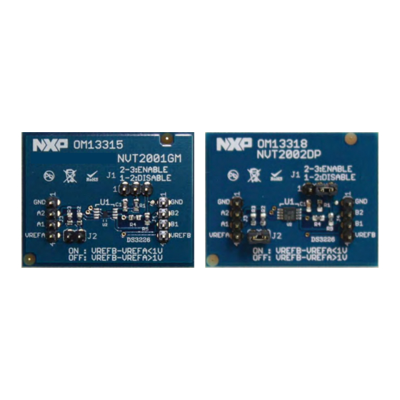
NVT2001GM and NVT2002DP demo boards 1. Introduction The NVT2001GM (OM13315) and NVT2002DP (OM13318) demo boards are designed to evaluate the NXP 1-channel or 2-channel bidirectional voltage level translators. The demo boards interface between device I/Os operating at different voltage levels. Since the... -
Page 4: Hardware Description
NVT2001GM and NVT2002DP demo boards 2. Hardware description 2.1 Schematic The demo boards contain footprints for the NVT2001GM and NVT2002DP devices, where the jumpers, headers, and passive components are shared. The NVT2001GM and NVT2002DP demo board schematic is shown in Figure 2. -
Page 5: Jumper And Header Functions
Jumper/header Function Notes J1 (3-pin) Device switch enable or disable Short pins 2 and 3 to enable the NVT2001GM or NVT2002DP control device (default). When pins 1 and 2 are shorted, the device is disabled. J2 (2-pin) Connects 10 kΩ pull-up resistors to Short pins 1 and 2 to connect 10 kΩ... -
Page 6: Legal Information
In no event shall NXP Semiconductors, its affiliates or their suppliers be liable Notwithstanding any damages that customer might incur for any reason to customer for any special, indirect, consequential, punitive or incidental whatsoever, NXP Semiconductors’... -
Page 7: Table Of Contents
UM10540 NXP Semiconductors NVT2001GM and NVT2002DP demo boards 6. Contents Introduction ......3 Hardware description .
Need help?
Do you have a question about the NVT2002DP and is the answer not in the manual?
Questions and answers