Table of Contents
Advertisement
Quick Links
UM11763
PCA9617ADP-ARD user manual
Rev. 1.0 — 22 July 2022
Document information
Information
Content
Keywords
PCA9617A, I
Abstract
The PCA9617ADP-ARD evaluation board is a daughterboard equipped with
an Arduino port, designated for easy testing and design of PCA9617A IC,
level translating FM+ I
IMXRT1050 EVK, LPCXpresso55S69 (LPC55S69-EVK) and i.MX 8M Mini
LPDDR4 EVK (8MMINILPD4-EVK, 8MMINID4-EVK), including GUI software
control. The board can be attached to any device equipped with an Arduino
port.
2
C-bus, level translator, repeater, Arduino port, EVK
2
C-bus repeater. The board is fully compliant with
User manual
Advertisement
Table of Contents

Subscribe to Our Youtube Channel
Related Manuals for NXP Semiconductors PCA9617ADP-ARD


Summary of Contents for NXP Semiconductors PCA9617ADP-ARD
- Page 1 PCA9617A, I C-bus, level translator, repeater, Arduino port, EVK Abstract The PCA9617ADP-ARD evaluation board is a daughterboard equipped with an Arduino port, designated for easy testing and design of PCA9617A IC, level translating FM+ I C-bus repeater. The board is fully compliant with IMXRT1050 EVK, LPCXpresso55S69 (LPC55S69-EVK) and i.MX 8M Mini...
- Page 2 UM11763 NXP Semiconductors PCA9617ADP-ARD user manual Revision history Date Description v.1.0 20220722 Initial version UM11763 All information provided in this document is subject to legal disclaimers. © 2022 NXP B.V. All rights reserved. User manual Rev. 1.0 — 22 July 2022...
- Page 3 UM11763 NXP Semiconductors PCA9617ADP-ARD user manual IMPORTANT NOTICE For engineering development or evaluation purposes only NXP provides the product under the following conditions: This evaluation kit is for use of ENGINEERING DEVELOPMENT OR EVALUATION PURPOSES ONLY. It is provided as a sample IC pre- soldered to a printed-circuit board to make it easier to access inputs, outputs and supply terminals.
-
Page 4: Introduction
PCA9617A, a level translating FM+ I C-bus repeater, produced by NXP Semiconductors. The evaluation board serves as a daughterboard that can be connected through an Arduino port to various Arduino compatible (including original Arduino Uno R3) EVK/motherboards with the purpose of testing and measuring the characteristics of the PCA9617A Device Under Test (DUT). -
Page 5: Assumptions
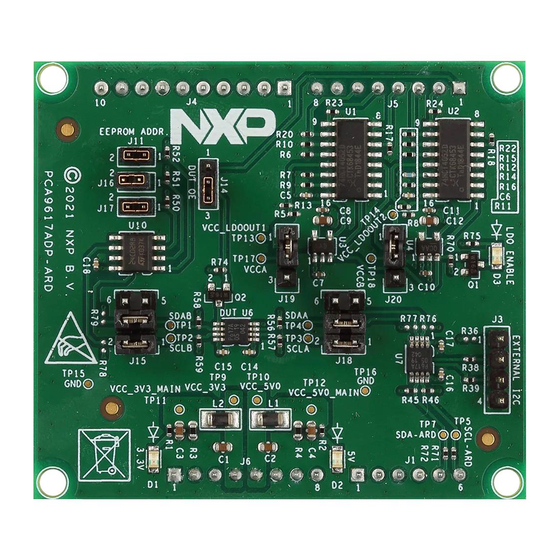
• Compliant with i.MX Mini LPDDR4 EVK board, including GUI (Windows 10). Note: For i.MX Mini LPDDR4 EVK Board it is necessary to use an IMX8MMINI-IARD interposer board between the EVK and PCA9617ADP-ARD daughterboard (see IMX8MMINI-IARD User Manual). 4.2 Kit featured components Figure 1 identifies the main components on the board. -
Page 6: Schematic Diagram
PCA9617ADP-ARD user manual The Arduino port connectors (J1, J4, J5, J6) are located on the bottom side of the board. Figure 1. The PCA9617ADP-ARD board picture, top view (up) and bottom view (down) 4.3 Schematic diagram The schematic diagram of PCA9617ADP-ARD is available at: http://www.nxp.com/... - Page 7 UM11763 NXP Semiconductors PCA9617ADP-ARD user manual The daughterboard uses only eight signal lines. Table 1 shows the pin chart of connectors, and the lines used in the circuit. See also the SPF-46669_A.pdf schematic file. Table 1. Arduino connectors pin chart Ref Des...
-
Page 8: I2C Bus Repeater/Level Translator
C bus repeater/level translator Figure 2 shows the I C-bus repeater and EEPROM section of PCA9617ADP-ARD schematic diagram. The I C-bus of the Arduino port (A5 – SCL and A4 – SDA), controlled by the EVK goes to side “B” of PCA9617A level translator/repeater (U7). U7 (the same as the DUT) works as an interface between 3.3 V fixed voltage I... - Page 9 UM11763 NXP Semiconductors PCA9617ADP-ARD user manual Figure 2. PCA9617ADP-ARD – I C-bus repeater/level translator section UM11763 All information provided in this document is subject to legal disclaimers. © 2022 NXP B.V. All rights reserved. User manual Rev. 1.0 — 22 July 2022...
-
Page 10: Programmable Power Supplies
NXP Semiconductors PCA9617ADP-ARD user manual 4.6 Programmable power supplies The PCA9617ADP-ARD contains two programmable power supplies: LDO1 and LDO2. Figure 3 depicts the LDO sections of the schematic diagram. LDO1 provides the power for VCCA, and LDO2 supplies VCCB power rail. Both regulators are controlled from the EVK through the Arduino port. -
Page 11: Jumpers And Test Points
NXP Semiconductors PCA9617ADP-ARD user manual Figure 3. PCA9617ADP-ARD – LDO1 (up) and LDO2 (down) section The enable input for both LDOs (U3 and U4) are controlled through an interlock loop circuit. Both regulators are disabled when “LDO_EN” are pulled down. This is accomplished when LDO1 switch (U1) is “2Z/2Y3 –... - Page 12 ON: E1 = 0 EEPROM ADDR (E1) OFF: E1 = 1 ON: E2 = 0 EEPROM ADDR (E2) OFF: E2 = 1 Figure 4. PCA9617ADP-ARD Jumper locations Table 5. PCA9617ADP-ARD test points Ref Des Test point/jumper label Description SDAB C SDA line, side B...
-
Page 13: Installing And Configuring Software Tools
PCA9617ADP-ARD daughterboard through the one of above mentioned EVKs. The GUI application is common for all three EVKs. The GUI software is also built to control two daughterboards: the PCA9617ADP-ARD and the PCA9846PW-ARD (both manufactured by NXP Semiconductors). For details regarding... - Page 14 J1 jumper shall be placed in position 5-6. If using an external power supply (connected to J2), the jumper J1 will be placed in position 1-2. 2. Insert the PCA9617ADP-ARD daughterboard on the Arduino connector of the EVK (see Figure 3.
-
Page 15: Using The Pca9617Adp-Ard With An Lpcxpresso55S69 Development Board
Figure 6. PCA9617ADP-ARD daughterboard/IMXRT1050 EVK board operation 6.2 Using the PCA9617ADP-ARD with an LPCXpresso55S69 development board Figure 7 shows the required hardware for operation of the PCA9617ADP-ARD and LPCXpresso55S69 EVK board. This configuration consists of: • One LPCXpresso55S69 EVK board • One PCA9617ADP-ARD daughterboard •... - Page 16 For more details regarding power up and operation of the LPCXpresso55S69 development board, see UM11158 - LPCXpresso55S69/LPCXpresso55S28 Development Boards User Manual. Figure 7. PCA9617ADP-ARD daughterboard and LPCXpresso55S69 motherboard, before starting The following steps describe how to assemble, program, and operate the configuration shown in Figure UM11763 All information provided in this document is subject to legal disclaimers.
-
Page 17: Mini Lpddr4 Evk Board
6.3 Using the PCA9617ADP-ARD with an i.MX 8M Mini LPDDR4 EVK board When an i.MX 8M Mini LPDDR4 EVK board is used with the PCA9617ADP-ARD board, a third board (IMX8MMINI-IARD interposer board) must be used, especially designed and built as an EVK – daughterboard interconnection. The EVK board i.MX 8M Mini LPDDR4 is not equipped with an Arduino port;... - Page 18 • One USB-A/USB Micro-B cable • A PC with Windows 10 operating system It is recommended to attach the PCA9617ADP-ARD to the Arduino connectors of the IMX8MMINI-IARD interposer board first, and then the resulting assembly to the i.MX 8M Mini LPDDR4 EVK. This can be done by plugging J1 connector located on the interposer board to J1003 connector on the EVK.
-
Page 19: Using Pca9617Adp-Ard With Another Device
Arduino port, and an EVK without an Arduino port. In the first case, firmware shall be developed according to PCA9617A specifications; to operate the board, attach PCA9617ADP-ARD daughterboard to the EVK. In the second case, using the Arduino connectors pin chart... -
Page 20: Gui Description
UM11763 NXP Semiconductors PCA9617ADP-ARD user manual GUI description A GUI application is available for the three EVK boards from NXP Semiconductors. The application is common for all three EVKs described in Section 6, and the following development boards: PCA9617ADP-ARD and PCA9846PW-ARD. - Page 21 UM11763 NXP Semiconductors PCA9617ADP-ARD user manual Figure 11. Graphical interface at start-up (“settings” tab activated by default) The second tab is Device Control. Clicking on this new tab, a new window appears (see Figure 12). In upper side of the window, the user can select the VCCA and VCCB power supply voltages from two drop-down lists.
-
Page 22: Abbreviations
Universal Serial Bus References 1. PCA9617A, Level translating Fm+ I C-bus repeater Product data sheet; NXP Semiconductors 2. MIMXRT1050-EVKB Board Hardware User’s Guide User manual; NXP Semiconductors 3. i.MX RT1050 Crossover Processors Data Sheet for Consumer Products Data sheet; NXP Semiconductors 4. - Page 23 CASPER, 320KB SRAM; 640 KB flash, USB HS, Flexcomm Interface, SDIO, 32-bit counter/timers, SCTimer/PWM, PLU, 16-bit 1.0 Msamples/sec ADC, Comparator, Temperature Sensor, AES, PUF, SHA, CRC, RNG Product data sheet; NXP Semiconductors 6. i.MX 8M Mini LPDDR4 EVKB Board Hardware User’s Guide User guide; NXP Semiconductors 7.
-
Page 24: Legal Information
NXP Semiconductors. In the event that customer uses the product for design-in and use in In no event shall NXP Semiconductors be liable for any indirect, incidental, automotive applications to automotive specifications and standards, punitive, special or consequential damages (including - without limitation - customer (a) shall use the product without NXP Semiconductors’... -
Page 25: Table Of Contents
Using the PCA9617ADP-ARD with an IMXRT1050 EVK board ........13 Using the PCA9617ADP-ARD with an LPCXpresso55S69 development board ...15 Using the PCA9617ADP-ARD with an i.MX 8M Mini LPDDR4 EVK board ......17 Using PCA9617ADP-ARD with another device ...............19 GUI description ..........20 Abbreviations ............
Need help?
Do you have a question about the PCA9617ADP-ARD and is the answer not in the manual?
Questions and answers