Advertisement
Quick Links
Advertisement

Related Manuals for SHANGRI-LA RIO ENTERTAINMENT UNIT SLRIOENTUOA


Summary of Contents for SHANGRI-LA RIO ENTERTAINMENT UNIT SLRIOENTUOA
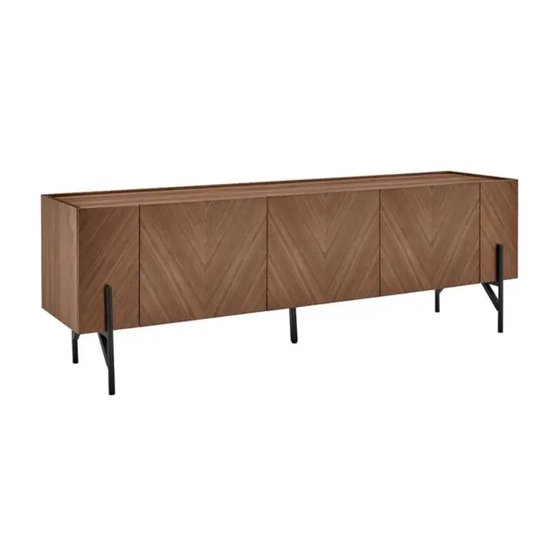
- Page 1 RIO ENTERTAINMENT UNIT SLRIOENTUOA & SLRIOENTUWA...
- Page 3 COMPONENTS Parts list SIZE CARTON NO. SIZE CARTON NO. 396x396x16 (x2) 1778x328x5 (x1) 1768x379x16 (x1) 396x197x16 (x1) 1768x396x16 (x1) 396x197x16 (x1) 353x379x16 (x1) 396x465x16 (x2) 353x379x16 (x1) 396x465x16 (x1) 1768x60x16 (x1)
- Page 4 Hardware A Cam Bolt (x26) B Cam Connector (x26) C Dowel (x24) D M7x50mm Bolt (x3) E Allen Key F M6x25 Screw (x2) G M6x30 (x11) H M6x16 (x2) I Flat Hinge J Bent Hinge (x4) (x2) Note: This product includes two different types of hinges. Ensure the correct ones are used during assembly.
- Page 5 ASSEMBLY Step 1: Attach the two legs (1) & (2) to the centre support (3) using the four M6x30 Screws (G). E Allen Key G M6x30 (x4)
- Page 6 Step 2: Attach the centre leg (4) to the centre support (3) using the two M6x16 Screws (H). E Allen Key H M6x16 (x2)
- Page 7 Step 3: Insert eight Cam Bolts (A) and eight Dowels (C) into parts (2) & (3) in the locations shown below. Important: Ensure the Dowels (C) are placed in the inner holes and the Cam Bolts (A) are in the outer holes. A Cam Bolt (x8) C Dowel (x8)
- Page 8 Step 4: • Insert eight Cam Connectors (B) into all the holes adjacent to the corresponding Cam Bolts. Note: Ensure the arrow on the Cam Connector (B) is facing the direction of the hole. • Attach parts (2), (3), (4) & (5) together by screwing the Cam Connectors (B) clockwise. B Cam Connector (x8)
- Page 9 Step 5: Insert 10 Cam Bolts (A) and 10 Dowels (C) into parts (1L) & (1R) in the locations shown below. A Cam Bolt (x10) C Dowel (x10)
- Page 10 Step 6: • Insert 10 Cam Connectors (B) into all the holes adjacent to the corresponding Cam Bolts. Note: Ensure the arrow on the Cam Connector (B) is facing the direction of the hole. • Attach parts (1L), (1R), (6) & (7) to the assembled frame by screwing the Cam Connectors (B) clockwise.
- Page 11 Step 7: • Secure the two Flat Hinges (H) to parts (8) & (10) using the included hinge fasteners. IMPORTANT: Ensure only the Flat Hinges (I) are used in this step. The Bent Hinges (J) will not fit. • Repeat with parts (9) and (11). I Flat Hinge (x4)
- Page 12 Step 9: • Insert eight Cam Bolts (A) and six Dowels (C) into parts (8) & (9) in the locations shown below. • Insert eight Cam Connectors (B) into all the holes adjacent to the corresponding Cam Bolt (A). Note: Ensure the arrow on the Cam Connector (B) is facing the direction of the hole. •...
- Page 13 Step 10: Secure the legs to the underside of the entertainment unit using the seven M6x30 Hex Screws (G). G M6x30mm Hex Screw (x7)
- Page 14 Step 11: Secure the legs in place using the two M6x25 Screws (F) from inside the entertainment unit. F M6x25 Screw (x2)
- Page 15 Step 12: Insert the three M7x50 Screws (D) in the rear of the entertainment unit. D M7x50mm Screw (x3)
- Page 16 Step 13: Secure part (10) to the entertainment unit assembly using the two Bent Hinges (J) and the included hinge fasteners. J Bent Hinges (x2)
- Page 17 Adjustments Adjust door up and Adjust door and back Adjust door left and down using screw A using screw C right using screw B Assembly Completed...
- Page 18 NOTES...
- Page 20 Need more information? We hope that this user guide has given you the assistance needed for a simple set-up. For the most up-to-date guide for your product, as well as any additional assistance you may require, head online to help.kogan.com...
Need help?
Do you have a question about the RIO ENTERTAINMENT UNIT SLRIOENTUOA and is the answer not in the manual?
Questions and answers