Advertisement
Quick Links
Advertisement

Related Manuals for SHANGRI-LA SLMANILBFWA


Summary of Contents for SHANGRI-LA SLMANILBFWA
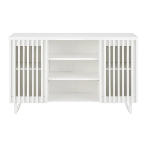
- Page 1 MANILA BUFFET SLMANILBFWA, SLMANILBFNA, SLMANILBFBA...
-
Page 3: Safety And Warnings
To avoid any damage to these items during transportation, the slide runners and slide tracks have been pre-assembled together in pairs. Each pair includes a slide runner and slide track. Before assembling your new Shangri-La unit, please separate the slide runners from the slide tracks according to the following instructions. - Page 4 Step 1: Extend the slide runners apart from the slide track. Step 2: Gently press the plastic release lever on the slide runner while pulling the slide runner and slide track apart from each other. Step 3: The slide runner and slide track should now be separated.
- Page 5 Step 2: Adjust the gap between the door and side panel. Top panel Door Side panel Loosen the screw slightly. Adjust the hinge to the right position (see steps 2a & 2b). then tighten the screw. Step 2a: Move the door in Step 2b: Move the door out Top panel Top panel...
- Page 6 Step 3: Adjust the gap between the two doors. Top panel Door Side panel Loosen or tighten the screw slightly to adjust the gap between the door panels (see step 3a & step 3b). Step 3a: Move the door right Step 3b: Move the door left Top panel Top panel...
- Page 7 COMPONENTS...
- Page 8 Parts list No Dimensions (mm) 340 x 585 x 15 2 340 x 585 x 15 3 340 x 585 x 15 4 394 x 1200 x 25 5 340 x 1199 x 15 6 322 x 326 x 15 7 322 x 482 x 15 8 336 x 594 x 2.5 9 246 x 594 x 2.5...
- Page 9 Hardware A Φ15x9.6 (x8) B L=35mm (x8) C Φ5.5x38 (x8) D Φ35mm (x4) E Φ4x15 (x24) F L=584mm (x1) G (x14) H Φ3x18 (x14) I Φ6x13x1 (x9) J Φ4x16 (x1) K (x1) L Φ6x30 (x6) M 25x340x105 (x2) N Φ=4mm (x1) O Φ6x35 (x2) P 15x25x1050 (x1) Q (x16)
- Page 10 ASSEMBLY Step 1: Using a Phillips screwdriver (not supplied), secure C screws as shown below. C Φ5.5x38 (x8)
- Page 11 Step 2: M 25x340x105 (x2) N Φ=4mm (x1) O Φ6x35 (x2) P 15x25x1050 (x1) I Φ6x13x1 (x2)
- Page 12 Step 3: I Φ6x13x1 (x6) L Φ6x30 (x6) N Φ=4mm (x1)
- Page 13 Step 4: B L=35mm (x8)
- Page 14 Step 5: Ensuring the arrows on B point towards the holes A will be placed into, use a Phillips screwdriver (not supplied) and secure B into part 4. F L=584mm (x1) A Φ15x9.6 (x8)
- Page 15 Step 6: Secure Q support pegs with R screws in the inner corners between parts labelled 1, 2, and 3 to the desired level. Place parts 6 and 7 on top. Cover the exposed screw holes and A nuts with S. Q (x16) R Φ3.5x10 (x16) S Φ20mm (x12)
- Page 16 Step 7: D Φ35 (x4) E Φ4x15 (x24)
- Page 17 Step 8: G (x14) H Φ3x18 (x14) Step 9: I Φ6x13x1 (x1) J Φ4x16 (x1) K (x1)
- Page 18 Step 10: Secure a screw (not supplied) through L to prevent the unit from toppling. TOPPLING FURNITURE WARNING: • It is strongly recommended that this product is permanently fixed to the wall. • Please seek professional advice if you are in doubt of what fixing device to use. •...
- Page 19 Assembly complete.
- Page 20 Need more information? We hope that this user guide has given you the assistance needed for a simple set-up. For the most up-to-date guide for your product, as well as any additional assistance you may require, head online to help.kogan.com...
Need help?
Do you have a question about the SLMANILBFWA and is the answer not in the manual?
Questions and answers