Autel MaxiCOM MK808 Manual
Automotive scanner
Hide thumbs
Also See for MaxiCOM MK808:
- Quick reference manual (2 pages) ,
- Manual (168 pages) ,
- Manual (114 pages)
Table of Contents
Advertisement
Quick Links
Trademarks
®
Autel
, MaxiSys
®
MaxiCheck
are trademarks of Autel Intelligent Technology Corp., Ltd.,
registered in China, the United States and other countries. All other marks
are trademarks or registered trademarks of their respective holders.
Copyright Information
No part of this manual may be reproduced, stored in a retrieval system or
transmitted, in any form or by any means, electronic, mechanical,
photocopying, recording, or otherwise without the prior written permission of
Autel.
Disclaimer of Warranties and Limitation of Liabilities
All information, specifications and illustrations in this manual are based on
the latest information available at the time of printing.
Autel reserves the right to make changes at any time without notice. While
information of this manual has been carefully checked for accuracy, no
guarantee is given for the completeness and correctness of the contents,
including but not limited to the product specifications, functions, and
illustrations.
Autel will not be liable for any direct, special, incidental, indirect damages or
any economic consequential damages (including the loss of profits).
IMPORTANT
Before operating or maintaining this unit, please read this manual carefully,
paying extra attention to the safety warnings and precautions.
For Services and Support
pro.autel.com
www.autel.com
1-855-288-3587/1-855-AUTELUS (North America)
0086-755-86147779 (China)
Support@autel.com
For technical assistance in all other markets, please contact your local selling
agent.
®
®
, MaxiDAS
, MaxiScan
®
®
, MaxiTPMS
i
®
, MaxiRecorder
, and
Advertisement
Table of Contents

Related Manuals for Autel MaxiCOM MK808


Summary of Contents for Autel MaxiCOM MK808
- Page 1 All information, specifications and illustrations in this manual are based on the latest information available at the time of printing. Autel reserves the right to make changes at any time without notice. While information of this manual has been carefully checked for accuracy, no...
-
Page 2: Safety Information
Safety Information For your own safety and the safety of others, and to prevent damage to the device and vehicles upon which it is used, it is important that the safety instructions presented throughout this manual be read and understood by all persons operating or coming into contact with the device. -
Page 3: Safety Instructions
Safety Instructions The safety messages herein cover situations Autel is aware of. Autel cannot know, evaluate or advise you as to all of the possible hazards. You must be certain that any condition or service procedure encountered does not jeopardize your personal safety. - Page 4 Refer to the service manual for the vehicle being serviced and adhere to all diagnostic procedures and precautions. Failure to do so may result in personal injury or damage to the test equipment. To avoid damaging the test equipment or generating false data, make sure the vehicle battery is fully charged and the connection to the vehicle DLC is clean and secure.
-
Page 5: Table Of Contents
CONTENTS 1 USING THIS MANUAL ................1 ................... 1 ONVENTIONS 2 GENERAL INTRODUCTION ..............3 COM D ................. 3 ISPLAY ABLET ..................7 CCESSORY 3 GETTING STARTED................9 ................... 9 OWERING ..................13 OWERING 4 DIAGNOSTICS OPERATIONS ..............14 ..................14 ETTING TARTED ................15 EHICLE DENTIFICATION... - Page 6 8 SETTINGS OPERATIONS ..............82 ......................82 ....................83 ANGUAGE ..................84 RINTING ETTING ................85 OTIFICATION ENTER ...................86 PDATE .....................87 BOUT ..................88 YSTEM ETTINGS ....................88 IRMWARE 9 UPDATE OPERATIONS .................90 10 SUPPORT OPERATIONS ...............93 ................93 RODUCT EGISTRATION .................94 UPPORT CREEN AYOUT ...................94 CCOUNT ..................95 OMPLAINT ..................97 OGGING...
- Page 7 ................118 ERVICE ROCEDURES 17 COMPLIANCE INFORMATION .............. 121 18 WARRANTY..................124 ..............124 IMITED ARRANTY...
-
Page 8: Using This Manual
Using this Manual This manual contains device usage instructions. Some illustrations shown in this manual may contain modules and optional equipment that are not included in your system. Conventions The following conventions are used. Bold Text Bold text is used to highlight selectable items such as buttons and menu options. - Page 9 Example: IMPORTANT Keep the cable away from heat, oil, sharp edges and moving parts. Replace damaged cables immediately. Hyperlink Hyperlinks, or links, that take you to other related articles, procedures, and illustrations are available in electronic documents. Blue italic text indicates a selectable hyperlink and blue underlined text indicates a website link or an email address link.
-
Page 10: General Introduction
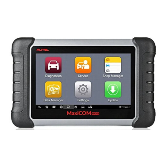
General Introduction When it comes to ultra-portability, MaxiCOM MK808 is your perfect companion. Installed with a fast quad-core processor, MK808 offers maximum convenience and swift diagnosis. The intuitive user screen makes using the device effortless through a 7-inch LCD touchscreen that displays at 1024 x 600 quality. - Page 11 Illuminates red when the Display Tablet is powered on and the battery level is below 15%. Figure 2-2 MaxiCOM MK808 Display Tablet Back View Collapsible Stand – extends from the back to allow hands-free viewing of the Display Tablet.
- Page 12 Built-in Battery Figure 2-3 MaxiCOM MK808 Display Tablet Top View Mini USB OTG Port Micro SD Card Slot – holds the micro SD card. 10. DB15-Pin Port – connects the main cable. 11. USB Port 12. Lock/Power Button – long press button to turn tablet off and on. Quick press button to lock screen.
-
Page 13: Technical Specifications
Technical Specifications Table 2-1 Specifications Item Description Recommended Use Indoor Operating System Android 4.4.4 Processor Cortex-A9 processor (1.5 GHz) Memory 32GB 7-inch capacitive touchscreen with Display 1024x600 resolution Mini USB 2.0 USB 2.0 Connectivity Wi-Fi Micro SD card (supports up to 32GB) ... -
Page 14: Accessory Kit
237.8 mm (9.4”) x 148.6 mm (5.9”) x 35.5 mm Dimensions (W x H x D) (1.4”) Net Weight 788 g (2.42 lb.) ISO9141-2, ISO14230-2,ISO15765, K/L-Line, Flashing Code, SAE-J1850 VPW, SAE-J1850 Supported Automotive PWM, ISO11898(Highspeed, Middlespeed, Protocols Lowspeed and Singlewire CAN,fault-tolerant CAN), SAE J2610,GM UART,UART Echo Byte Protocol, Honda Diag-H Protocol, TP2.0, TP1.6 Accessory Kit... - Page 15 User Manual Tool operations instructions. Quick Guide Device connection and diagnostic software update instructions.
-
Page 16: Getting Started
The system boots up, and displays the lock screen. Slide the Lock icon to the left to access the MaxiCOM Job Menu or slide to the right to unlock. Figure 3-1 Sample MaxiCOM MK808 Job Menu Application Buttons... - Page 17 NOTE The tablet screen is locked by default upon startup. It is recommended to lock the screen when not in use to protect the information in the system and conserve the power. Almost all operations on the tablet are controlled through the touchscreen. The touchscreen navigation is menu driven, which allows you to quickly locate the test procedure, or data that you need, through a series of choices and questions.
- Page 18 Quick Link Operations on page 113. Provides quick search for the supported Function functions and vehicles of Autel diagnostic tools. Viewer Function Viewer Operations on page 114. Locator and Navigation Buttons Operations of the Navigation buttons at the bottom of the screen are...
- Page 19 Table 3-2 Locator and Navigation Buttons Button Name Description Indicates the location of the screen. Swipe the Locator screen left or right to view the previous or next screen. Back Returns to the previous screen. Android Returns to Android System’s Home screen. Home Displays a list of applications that are currently in Recent...
-
Page 20: Powering Down
Table 3-3 Shortcuts Panel Buttons Button Name Description Calculator Launches calculator when pressed. Clock Launches clock when pressed. Wi-Fi Enables/disables Wi-Fi when pressed. Enables/disables Airplane Mode when Airplane Mode pressed. Launches the Android System Settings System Settings screen when pressed. Powering Down All vehicle communications must be terminated before shutting down the Display Tablet. -
Page 21: Diagnostics Operations
(ABS), airbag system (SRS) and more. Getting Started The Diagnostics operations require connecting the MaxiCOM MK808 to the test vehicle’s DLC using the main cable. Vehicle Menu Layout When the tablet is properly connected to the vehicle, the platform is ready to start vehicle diagnosis. -
Page 22: Vehicle Identification
Top Toolbar Buttons The operations of the toolbar buttons at the top of the screen are listed and described in the table below: Table 4-1 Top Toolbar Buttons Button Name Description Home Returns to the MaxiCOM Job Menu. Displays a dropdown list; tap Auto Detect for auto VIN detection;... - Page 23 Auto VIN Scan Manual VIN Input Automatic Selection Manual Selection Auto VIN Scan The MaxiCOM diagnostic system features the latest VIN-based Auto VIN Scan function to identify vehicles with just one touch, enabling the technician to quickly identify the vehicle, san all the diagnosable ECUs on the vehicle and perform diagnostics on the selected system.
- Page 24 Figure 4-3 Sample Auto VIN Screen 2 Review the information to ensure it is correct. Tap Yes to confirm the vehicle or NO if the information is not correct. Figure 4-4 Sample Vehicle Profile Screen The tool will establish communication with the vehicle to read control unit information.
- Page 25 Figure 4-5 Sample Diagnostic Screen Manual VIN Input For some vehicles that not supporting the Auto VIN Scan function, the MaxiCOM diagnostic system allows you to enter the vehicle VIN manually. To perform Manual VIN Input Tap the Diagnostics application button from the MaxiCOM Job Menu.
- Page 26 Tap Done. The vehicle will be identified and the Vehicle Diagnostics screen will display. Tap Cancel to exit Manual Input. Automatic Selection In some cases when users have selected the vehicle brand instead of performing Auto VIN Scan, the system will still provide an option for vehicle VIN scan.
-
Page 27: Navigation
This mode of vehicle selection is menu driven, repeat the first two steps from the automatic selection operation and tap Manual Selection. Follow the on- screen prompts to make a series of choices to select the correct vehicle. Press the Back button at the bottom right corner of the screen to return to the previous step. - Page 28 Operations on page 76. Records the communication data and ECU information of the test vehicle. The saved data can be reported and sent to Autel’s technical center via Data the Internet. Logging You can go to the Support application to follow up...
- Page 29 displays. To submit Data Logging reports in Diagnostics Tap the Diagnostics application button from the MaxiCOM Job Menu. The Data Logging button on the diagnostic toolbar is available throughout the Diagnostics operations. Tap the Data Logging button. The button displays blue during the active recording process.
-
Page 30: Diagnosis
Screen Messages Screen messages appear when additional input is needed before proceeding. There are three main types of on-screen messages: Confirmation, Warning, and Error. Confirmation Messages This type of messages usually displays as an “Information” screen that informs you when you are about to perform an action that cannot be reversed or when an action has been initiated and your confirmation is needed to continue. - Page 31 There are two options available when accessing the Diagnosis section: Auto Scan – starts auto scanning for all the available systems on the vehicle. Control Units – displays a selection menu of all available control units of the test vehicle. After a section is made and the tablet establishes communication with the vehicle, the corresponding function menu or selection menu displays.
- Page 32 Column 2 – displays the scanned systems. Column 3 – displays the diagnostic indicators describing test results. These indicators are defined as follows: : Indicates that the scanned system may not support the code reading function, or there is a communication error between the Display Tablet and the control system.
- Page 33 Control Units This option allows you to manually locate a required control system for testing through a series of choices. Follow the menu driven procedures and make proper selection each time; the program will guide you to the diagnostic function menu after selections are made. Figure 4-9 Sample Function Menu The Function Menu options vary slightly for different vehicles.
- Page 34 Identify the test vehicle by selecting from the menu options. Select the Diagnosis section. Locate the required system for testing by Auto Scan or through menu driven selections in Control Units. Select the desired diagnostic function from the Function Menu. ECU Information This function retrieves and displays the specific information for the tested control unit, including unit type, version numbers and other specifications.
- Page 35 some vehicles, freeze frame data can also be retrieved for viewing. The sample Read Codes screen displays as below: Figure 4-12 Figure 4-11 Sample Read Codes Screen Diagnostics Toolbar Buttons – see Table 4-2 Diagnostics Toolbar Buttons on page 21 for detailed descriptions of the operations for each button.
- Page 36 Before performing this function, make sure the vehicle’s ignition key is in the ON (RUN) position with the engine off. To erase codes Tap Erase Codes from the Function Menu. A warning message displays to inform you of data loss if this function is completed.
- Page 37 of the screen and the toolbar buttons will display. See Table 4-2 Diagnostics Toolbar Buttons on page 21 for detailed descriptions of the operations for each button. Main Section Name Column – displays the parameter names. Check Box – tap the check box on the left side of the parameter name to make item selection.
- Page 38 When this mode is applied, three control buttons will display on the right side of the parameter item, allowing you to manipulate the display status. Text Button – resumes Text Display Mode. Scale Button – changes the scale values, which are displayed below ...
- Page 39 Functional Buttons The operations of available functional buttons on Live Data screen are described below: Back – returns to previous screen or exits the function. Record – starts recording the retrieved live data; the recorded data is then stored as a video clip in the Data Manager application for future reviews.
- Page 40 Figure 4-13 Sample Setting Mode in Live Data There are four navigation buttons on top of the Setting mode screen. Selected Button – displays the configuration screen on which you can set the threshold values, an upper limit and a lower limit, for triggering the buzzer alarm.
- Page 41 maximum value. Tap the ON/OFF button on the right side of the Buzzer Alarm button to turn it on or off. Tap Done to save the setting and return to the Live Data screen; or tap Cancel to exit without saving. If the threshold limits are successfully set, two horizontal lines will appear on each of the data graphs (when Waveform Graph Mode is applied) to indicate the alarming point.
-
Page 42: Generic Obd Ii Operations
recording start point. Tap Done to save the setting and return to the Live Data screen; or tap Cancel to cancel without saving and exit Setting. Done Button - confirms and saves the setting, and returns you to the Live Data screen. - Page 43 Select a specific protocol under the Protocol option. Wait for the OBD II Diagnostic Menu to display. Figure 4-14 Sample OBD II Diagnostic Menu NOTE ○ Tapping the button beside the function name to display additional function information. Select a function option to continue. ...
- Page 44 DTC & FFD When this function is selected, the screen displays a list of Stored Codes and Pending Codes. When the Freeze Frame data of certain DTCs are available for viewing, a snowflake button will display on the right side of the DTC item. The erase codes function can be applied by tapping the Clear DTC button at the bottom of the screen.
- Page 45 Test results reported by this service do not necessarily indicate a faulty component or system. If test results indicate another failure after additional driving, then a DTC is set to indicate a faulty component or system, and the MIL is illuminated. ...
-
Page 46: Exiting Diagnostics
On-Board Monitor This option allows you to view the results of On-Board Monitor tests. The tests are useful after servicing or after erasing a vehicle’s control module memory. Component Test This service enables bi-directional control of the ECM so that the diagnostic tool is able to transmit control commands to operate the vehicle systems. - Page 47 Or tap the Vehicle Swap button on the diagnostics toolbar to return to the Vehicle Menu screen. From the Vehicle Menu screen, tap the Home button on the top toolbar; or tap the Back button on the navigation bar at the bottom of the screen.
-
Page 48: Service Operations
Service Operations The Service section is specially designed to provide you with quick access to the vehicle systems for various scheduled service and maintenance performances. The typical service operation screen is a series of menu driven executive commands. By following the on-screen instructions to select appropriate execution options, enter correct values or data, and perform necessary actions, the system will guide you through the complete performance for various service operations. - Page 49 NOTE All required work must be carried out before the service indicators are reset. Failure to do so may result in incorrect service values and cause DTCs to be stored by the relevant control module. NOTE For some vehicles, the scan tool can perform added functionality to reset additional service lights (maintenance cycle, service interval).
- Page 50 service. Using CBS Reset UDS as an example. Tap CBS Reset UDS on the Oil Reset function list to start the operation. The screen will guide you to confirm the date and time, if the displayed date and time are correct, tap Yes to confirm. If not, tap No and go to the Settings menu to set the correct date and time.
-
Page 51: Electronic Parking Brake (Epb) Service
Figure 5-3 Sample Oil Reset Service Screen 2 Tap on the value you want to reset and then tap the Reset button on the right bottom of the screen. Figure 5-4 Sample Oil Reset Service Screen 3 When the reset is done, the availability would display as 100%. Tap ESC to exit. - Page 52 Ensure that the EPB control system is reactivated after the maintenance work has been completed. NOTE Autel accepts no responsibility for any accident or injury arising from the maintenance of the Electronic Parking Brake system. To perform EPB functions Tap the Service application button from the MaxiCOM Job Menu.
- Page 53 Figure 5-5 Sample EPB Function List Follow the step-by-step on-screen instruction to complete the service. Press OK button to exit. EMF Star-up This service function would start the parking brake, it must be conducted after the following repairs: Replacing an EMF control unit. ...
- Page 54 bottom left to exit. Tap on the action taken to continue. Figure 5-7 Sample EMF Star-up Screen 2 A screen will display to remind you that the fault memory of the parking brake control unit will be deleted, press Continue to proceed or the Back button to exit.
-
Page 55: Bms
Parking Brake: Workshop Mode This service is used to activate and deactivate the so-called installation position for the Automatic Hold brake. In this mode, the parking brake is moved into the opened position and temporarily deactivated for personal protection. The installation position must be activated for the following repairs: ... - Page 56 addition to performing the battery reset. Consult the vehicle manual for additional vehicle-specific information. Register Battery Replacement This option allows displaying the mileage reading of last battery replacement, registering the battery replacement after replacing a new battery and informing the power management system that a new battery has been fitted to the vehicle.
- Page 57 Tap on the service to perform. In this case, it is function 1. Display kilometer reading at last battery change and one before last. A notice screen displays. Figure 5-10 Sample BMS Screen 1 Read carefully the complete information and press Continue. Figure 5-11 Sample BMS Screen 2 Check the battery capacity and the battery replacement information displayed.
- Page 58 Tap on function 1 to return to the selection screen or tap function 2 to end the service function. Figure 5-12 Sample BMS Screen 3 To register the battery replacement Tap on the corresponding service you want to carry out. In this case, it is function 2 Register battery replacement.
- Page 59 Figure 5-14 Sample BMS Screen 5 Enter battery replacement: Same capacity Enter battery replacement: Different capacity Enter battery replacement: Changing from the normal lead-acid battery (white housing) to AGM battery (black housing) End service function. Using function 1 as an example. Figure 5-15 Sample BMS Screen 6 Read carefully the information on the screen and tap Yes to continue.
-
Page 60: Steering Angle Sensor (Sas) Service
Follow the on-screen instructions to input the data matrix code labeled on the newly installed battery. Tap OK to continue. Figure 5-16 Sample BMS Screen 7 Tap Continue once the code was accepted and the exchange is complete. Figure 5-17 Sample BMS Screen 8 Steering Angle Sensor (SAS) Service Steering Angle Sensor Calibration permanently stores the current steering wheel position as the straight-ahead position in the steering angle sensor... - Page 61 NOTE AUTEL accepts no responsibility for any accident or injury arising from servicing the SAS system. When interpreting DTCs retrieved from the vehicle, always follow the manufacturer’s recommendation for repair.
- Page 62 Tap the needed service in the SAS function list. The list may vary by vehicle. Figure 5-18 Sample SAS Function Menu Steering Angle Sensor Calibration This function allows users to perform steering angle sensor calibration and clear records. Available function options vary by vehicle. Tap Steering Angle Sensor Calibration from the SAS function menu to enter the function screen.
-
Page 63: Dpf Service
Figure 5-19 Sample SAS Function Screen 1 A confirmation message will display when the operation is complete. A message will display if operation could not be completed because of an existing issue. Repair problem after exiting the diagnostics application. Figure 5-20 Sample SAS Function Screen 2 DPF Service The DPF function allows you to carry out numerous functions to the Diesel Particulate Filter system. - Page 64 The ECM monitors driving style and selects a suitable time to employ regeneration. Cars driven primarily at idling speed and low load will attempt to regenerate earlier than cars driven with higher loads and at higher speed. For regeneration to occur, a prolonged high exhaust temperature must be obtained.
- Page 65 Figure 5-21 Sample DPF Service Function Menu Starting Basic Inspection Quantity This function enables you to start fuel delivery matching. Tap Starting Basic Inspection Quantity from the service functions menu to enter the service screen. The tool communicates with the vehicle and reads the fault codes memory.
- Page 66 [1] Enter New Value for Adjustment From the Starting Basic Inspection Quantity menu, tap [1] and the screen displays as below. Figure 5-23 Sample Enter New Value Screen After entering the value, tap OK to save the value to the tool. Tap ESC to exit the operation.
- Page 67 The tool communicates with the vehicle and reads the fault codes memory. Follow the on-screen instructions to finish this procedure. Then the tool will display as below. Press the corresponding number button to perform the desired function. Figure 5-24 Sample Injection Rate Screen [1] Enter New Value for Adjustment From the Injection Rate menu, tap [1] and the screen displays as below.
- Page 68 [2] Reset Adjustment to 100% Once the [2] is pressed, the tool will automatically reset the value to 100%. [3]/[4] Store Data and Exit When the injection volume adjustment is completed, select [3] and OK to store the new value in the control units; or select [4] and OK to retain the old value.
- Page 69 Figure 5-26 Sample Regeneration Confirmation Screen Follow the on-screen instructions to perform the particle filter regeneration and tap OK. Figure 5-27 Sample Regeneration Status Screen When the particle filter regeneration is complete, the tool will ask for a confirmation to exit. Tap Repeat to re-check the status or tap End to exit.
- Page 70 Figure 5-28 Sample Repeat Screen NOTE In the case of a particle filter heavily loaded with soot, it can occur that the regeneration request is blocked again after a short time or is not released. In this case, it is required to regenerate the particle filter by driving the vehicle for approximately 30 minutes at a constant speed.
- Page 71 If there are DPF-related codes stored in DDE, the screen displays as below. Select OK to continue or Cancel to exit this function. Figure 5-29 Sample Codes Screen The tool displays a list of particle filter test. Select the corresponding button to perform the desired test [1] [2] [3] [4] [5].
-
Page 72: Tire Pressure Monitor System (Tpms) Service
Tire Pressure Monitor System (TPMS) Service The TPMS service function include displaying sensor IDs from the vehicle’s ECU, inputting TPMS sensor replacement IDs and testing sensors. Figure 5-30 Sample TPMS Function Menu Select tire pressure sensor replacement (Front left wheel sensor) as an example. - Page 73 Figure 5-31 Sample Tire Pressure Sensor Replacement Screen Tap Front left wheel sensor on the tire pressure sensor replacement menu. Enter the 8 digit sensor identification as required. Press OK. Figure 5-32 Sample Sensor ID Input Screen Continue to select tire position and enter sensor IDs. A message will display when the entered IDs have been registered to the vehicle.
-
Page 74: Immo Service
On completion of the drive cycle, carry out the tire pressure monitor system test application. IMMO Service An immobilizer is an anti-theft mechanism that prevents an automobile’s engine from starting if the correct ignition key is not used or other device is present. - Page 75 NOTE To complete key fob programming, you need to acquire the Security Code, which can be acquired through the Security Code Read function in hot functions. Before programming, please check and erase the fault codes. Read the on-screen information carefully and follow the instructions to complete the operation.
-
Page 76: Shop Manager Operations
Shop Manager The Shop Manager application manages the workshop information including customer information records and test vehicle history records. There are three main functions available: Vehicle History Workshop Information Customer Manager The operations of these functions of the Shop Manager application are controlled by the toolbar buttons, which are listed and described in the table below: Table 6-1 Top Toolbar Buttons in Shop Manager... -
Page 77: Vehicle History
Button Name Description Tap this button to create a new customer account Account file. Tap this button to open a note form. Audio, video, History Notes image and text files may be attached. Tap this button to display the Vehicle History with Vehicle History corresponding test vehicle records. - Page 78 Tap the Diagnostics button at the bottom of the thumbnail of a vehicle record item. Or, Or, tap the vehicle record thumbnail to view record. A Historical Test record sheet displays, check the recorded information of the recorded test vehicle, and tap the Diagnostics button on the upper right corner.
-
Page 79: Workshop Information
relevant files or images. NOTE The vehicle VIN number, or license and the customer information account are correlated by default. Tap Add to Customer to supplement a Historical Test record sheet to an existing customer account, or add a new associated account with the test vehicle record. -
Page 80: Customer Manager
Cancel to exit without saving. Customer Manager Use the Customer Manager function to create and edit customer accounts and correlate with the associated test vehicle history records. To create a customer account Tap the Shop Manager application on the MaxiCOM Job Menu. Select Customer Manager. - Page 81 Select a customer account by tapping the corresponding name card. A Customer Information sheet displays. Tap the Edit button on the top toolbar to start editing. Tap the Delete Customer Information button. A confirmation message displays. Tap OK to confirm the command, and the account is deleted. Tap Cancel to cancel the request.
- Page 82 Main Section – displays the note list on the left column and the detail information of the selected note displays on the right column. Table 6-2 Function Buttons in History Notes Button Name Description Returns to the previous screen. Back Deletes the selected note.
-
Page 83: Data Manager Operations
Data Manager The Data Manager application is used to store, print, and review the saved files. Most operations are controlled through the toolbar. Selecting the Data Manager application opens the file system menu. Different file types are sorted separately under different options, there are five types of information files to be viewed or played back. - Page 84 Image Files The Image section contains all captured screenshot images. Figure 7-2 Sample Image Screen Toolbar Buttons – used to edit, print and delete the image files. See the following table for detailed information. Main Section – displays the stored images. Table 7-1 Toolbar Buttons in Image Button Name...
- Page 85 > Support & Updates > Firmware & Downloads > UPDATE CLIENT, and install to your PC. The Maxi PC Suite consists of Autel Printer, MaxiSys Pinter and PC Suite. Double click on Setup.exe item. Select the installation language and the printer driver installation wizard will load.
- Page 86 Click on Finish to complete the installation procedure. To delete selected images Select Data Manager application from the MaxiCOM Job Menu. Select Image to access the JPG database. Tap the Enter Edit button to display the editing toolbar. Select the images that need to be deleted by tapping the thumbnail images, the selected thumbnail displays a tick icon at the bottom right corner.
- Page 87 Figure 7-3 Sample Data Playback Screen Drop-down Toolbar – tap the button at the top center of the screen to open the Drop-down Toolbar. Main Section – displays the recorded data frames. Navigation Toolbar – allows you to manipulate data playback. Use the Navigation Toolbar buttons to playback the record data from frame to frame.
- Page 88 records of all sent or unsent (saved) data logs on the diagnostic system. For more details, please refer to Data Logging of Support operation on page 97.
-
Page 89: Settings Operations
Settings Selecting Settings application opens a setup screen to adjust the default setting and view information about the MaxiCOM system. There are eight system settings: Unit Language Printing Setting Notification Center Auto Update About ... -
Page 90: Language
Figure 8-1 Sample Unit Setting Screen Language This option allows you to adjust the display language for the MaxiCOM system. To adjust the language setting Tap the Settings application on the MaxiCOM Job Menu. Tap the Language option on the left column. Select the required language. -
Page 91: Printing Setting
Printing Setting This option allows you to print via Wi-Fi connection. To setup the printer connection Tap the Settings application on the MaxiCOM Job Menu. Tap the Printing Setting option on the left column. Tap the Print via Network item to activate the printing function that enables the device to send files to the printer through the PC via Wi- Fi connection. -
Page 92: Notification Center
Notification Center The Notification Center function configures the MaxiCOM tablet to receive regular system and service update notifications from Autel. To ensure you receive all such notifications, keep this function on at all times. Internet access is required. -
Page 93: Auto Update
Auto Update The Auto Update allows the tool to automatically update the operating system, the MaxiCOM system and vehicle software. Tap the button on the right side of each software update to perform and set the time the automatic update should be done. -
Page 94: About
Figure 8-5 Sample Set Time Screen About The About screen lists the MaxiCOM’s version, hardware, and serial number. To check the MaxiCOM product information in About Tap the Settings application on the MaxiCOM Job Menu. Tap the About option on the left column. The product information screen displays on the right. -
Page 95: System Settings
System Settings Access the Android background system setting screen to adjust operating system settings including wireless and network settings, sound and display and system security settings. Android device information is also displayed. To enable the App Switcher function Tap the Settings application on the MaxiCOM Job Menu. Tap the System settings option on the left column. - Page 96 Figure 8-7 Sample Firmware Screen...
-
Page 97: Update Operations
Settings application, a notification message will display when an update is available. (See Notification Center page 85 for details). Figure 9-1 Sample Update Screen – for MaxiCOM MK808 ① Navigation and Controls Home Button – returns to the MaxiCOM Job Menu. - Page 98 for example: a vehicle make. ② Status Bar Left Side – displays the MaxiCOM device model information and serial number. Right Side – displays an update progress bar indicating the completion status. ③ Main Section Left Column – displays vehicle icons and update software version ...
- Page 99 resume the update. The update will resume from the point at which it was paused. The firmware will be installed automatically once its download has completed. The previous version will be replaced.
-
Page 100: Support Operations
On the Sign In page, input your account ID and password. If you are a new Autel product user and do not have an account yet, click the Create Autel ID button on the left side. -
Page 101: Support Screen Layout
Support Screen Layout The Support application screen is navigated with four simple buttons on the top navigation bar, operation of each is described below in turn from left to right: Home Button – returns to the MaxiCOM Job Menu. Back –... -
Page 102: User Complaint
User Info – displays detailed information of your registered on-line Autel account, such as your Autel ID, Name, Address and other contact information. Device Info – displays the registered product information, including the Serial Number, Registration Date, Expire Date, and Warranty Period. - Page 103 Period Filter – displays only the complaint records within the defined period. Status Filter – displays the corresponding complaint records according to the selected case status. New Complaint Button – starts a new complaint case. Complaint List The complaint list normally displays all the complaint records of all time and all status by default.
-
Page 104: Data Logging
Select the required processing time on the last section according to the urgency of the case. Tap Submit to send the completed form to Autel’s online service center, or tap Reset to refill it. The submitted complaints will be processed and responded to by customer service personnel. -
Page 105: Communities
Tap Send to send your message to the technical center. Communities The Communities section launches and synchronizes with the Technical Forums on Autel’s official website www.autel.com. The community’s forum allows for discussion of technical issues, the sharing of information or tips with other members in Autel’s online support communities. -
Page 106: User Profile
To start a discussion Tap Start a discussion on the Communities Home screen. A list of the major forums is displayed. Select a desired community according to the subject you are interested in. Enter your topic and the discussion content in the appropriate input field. -
Page 107: Training Channels
Stuff – displays a list of your posts in the various forums. Training Channels The Training section provides quick links to Autel’s online video accounts. Select a video channel by language to see all the available online tutorial videos. -
Page 108: Academy Operations
Academy Autel provides various tutorials and technical bulletins written by top-notch technicians and product experts. Please review the materials on the tablet or view additional technical articles on the online forum by clicking on click on the links provided. -
Page 109: Remote Desk Operations
The Remote Desk application launches the TeamViewer Quick Support program, a simple, fast and secure remote control screen. Use this application to receive ad-hoc remote support from Autel’s support technicians by allowing them to control your MaxiCOM tablet on their PC via the TeamViewer software. - Page 110 remote control request. A popup will display to ask for your confirmation to allow remote control on your device. Tap Allow to accept, or tap Deny to reject. Refer to the associated TeamViewer documents for additional information.
-
Page 111: Maxifix Operations
MaxiFix The MaxiFix application launches the on-line troubleshooter database, which not only provides you virtually all common diagnostic trouble code (DTC) database for most vehicles, but also serves as a forum allowing for technicians to network with other MaxiCOM users, and gives you access to a vast database of repair and diagnostic tips along with proven filed fixes. - Page 112 to select vehicles and perform searches. The Main Screen – located at the center of the screen displaying content based on the vehicle attributes and keywords specified. The tabs on the main screen vary in accordance with the section selected on the Navigation Menu, allowing you to switch between functions.
- Page 113 Select the engine of the vehicle from the list. After completing the vehicle selection procedure, the identified vehicle is shown on the Header. Terminology MaxiFix Tip A MaxiFix Tip offers a detailed outline of an actual vehicle repair. Combined with proven results and vehicle specific data, this all-in-one information source provides quick and easy repair solutions.
-
Page 114: Operations
assessment by making clear the nature of an automotive problem so that beginner and advanced technicians can make effective repairs. Real Fix Tips – provides repair tips from actual shop practices and are presented in an easy to understand Complaint, Cause, Correction format. - Page 115 Home Home is the first option on the Navigation Menu at the bottom of the screen. Tap to open your MaxiFix home page. There is a list of questions posted on the community, and you can scroll down the page to the bottom and view more questions by tapping “View More”.
- Page 116 Marked Posts – opens a list with links to Tips and discussions that you are actively participating in. My Profile – allows you to view your Autel account information including: your Autel ID, personal information, MaxiFix score, phone number and...
- Page 117 Vehicle Preference – used to set up a list of preferred vehicles. The preferred list allows you to limit the choices that display on the “Select Vehicle” list to specific years, and makes. Click “Set Year” or “Set Make” to set your preferred models.
- Page 118 members’ profile by clicking their portrait. Information included in your profile determines how you are presented to the community, and what type of information will be sent to you from the community. My Messages My Messages, the fifth option on the Navigation Menu at the bottom of the screen, shows a list of message notification that are relevant to your activities in the Question section.
- Page 119 To close a question, you need to select the question’s response message from the message list on “My Messages” page first, then tap “Adopted Answer” and select “Close Question”. Tap the “Cancel” button to cancel your submission and return to My Messages page. It is strongly recommended that you share your repair solutions before closing a question.
-
Page 120: Quick Link Operations
Quick Link The Quick Link application provides access to Autel’s official website and to other popular automotive service websites. These sites are invaluable resources of automotive information and repair data and include forums, video training and expert consultation. Figure 14-1 Sample Quick Link Screen ... -
Page 121: Function Viewer Operations
Function Viewer The Function Viewer allows you to search the supported functions. There are two ways of searching, by vehicle or by function. To search by the vehicle Tap the Function Viewer application on the MaxiCOM Job Menu. The Function Viewer application screen displays. Tap the tool name on the top left to drop down the tool list, tap the one you want to search. - Page 122 Figure 15-2 Sample Function Viewer Screen 2 To search by the functions Tap the Function Viewer application on the MaxiCOM Job Menu. The Function Viewer application screen displays. Tap the tool name on the top left to drop down the tool list, tap the one you want to search.
-
Page 123: Maintenance And Service
Maintenance and Service Maintenance Instructions The following shows how to maintain your devices, together with precautions to take. Use a soft cloth and alcohol or a mild window cleaner to clean the touch screen on the tablet. Do not use any abrasive cleansers, detergent, or automotive chemicals to the tablet. -
Page 124: Troubleshooting Checklist
Your device may have not been connected to the charger properly. Check the connector. NOTE If your problems persist, please contact Autel’s technical support personnel or your local selling agent. About Battery Usage Your tablet is powered by a built-in Lithium-ion Polymer battery. This means that, unlike other forms of battery technology, you can recharge your battery while some charge remains without reducing your tablet’s autonomy due to... -
Page 125: S Ervice P Rocedures
DANGER The built-in Lithium-ion Polymer battery is factory replaceable only; incorrect replacement or tampering with the battery pack may cause an explosion. Do not use a damaged battery charger. Do not disassemble or open crush, bend or deform, puncture or shred. ... -
Page 126: Technical Support
Email: support@autel.com Address: 6th-10th floor, Building B1, Zhiyuan, Xueyuan Road, Xili, Nanshan, Shenzhen, 518055, China AUTEL NORTH AMERICA Phone: 855-AUTEL-US (855-288-3587) Monday-Friday 9am-6pm EST Website: www.autel.com Email: ussupport@autel.com Address: Suite 200, 175 Central Avenue, Farmingdale, New York, USA. - Page 127 Address: 155 Islington Street, Melbourne, Collingwood, VIC Repair Service If it becomes necessary to return your device for repair, please download the repair service form from www.autel.com, and fill it in. The following information must be included: Contact name ...
-
Page 128: Compliance Information
Compliance Information FCC Compliance FCC ID: WQ8-1610MX808 This device complies with Part 15 of the FCC rules and Industry Canada’s license-exempt RSSs. Operation is subject to the following two conditions: This device may not cause harmful interference. This device must accept any interference received, including interference that may cause undesired operation. - Page 129 -- Increase the separation between the equipment and receiver. -- Connect the equipment into an outlet on a circuit different from that to which the receiver is connected. -- Consult the dealer or an experienced radio/TV technician for help. Changes or modifications not expressly approved by the party responsible for compliance could void the user’s authority to operate the equipment.
- Page 130 CE COMPLIANCE This product is declared to conform to the essential requirements of the following Directives and carries the CE mark accordingly: EMC Directive 2014/30/EU R&TTE Directive 1999/5/EC Low Voltage Directive 2014/35/EU...
-
Page 131: Warranty
Warranty Limited One Year Warranty Autel Intelligent Technology Corp., Ltd. (the Company) warrants to the original retail purchaser of this MaxiCOM Diagnostic Device, that should this product or any part thereof during normal consumer usage and conditions, be proven defective in material or workmanship that results in product failure... - Page 132 IMPORTANT All contents of the product may be deleted during the process of repair. You should create a back-up copy of any contents of your product before delivering the product for warranty service.
Need help?
Do you have a question about the MaxiCOM MK808 and is the answer not in the manual?
Questions and answers