Table of Contents
Advertisement
Quick Links
Trademarks
®
Autel
, MaxiSys
®
MaxiCheck
are trademarks of Autel Intelligent Technology Corp., Ltd.,
registered in China, the United States and other countries. All other marks
are trademarks or registered trademarks of their respective holders.
Copyright Information
No part of this manual may be reproduced, stored in a retrieval system or
transmitted, in any form or by any means, electronic, mechanical,
photocopying, recording, or otherwise without the prior written permission of
Autel.
Disclaimer of Warranties and Limitation of Liabilities
All information, specifications and illustrations in this manual are based on
the latest information available at the time of printing.
Autel reserves the right to make changes at any time without notice. While
information of this manual has been carefully checked for accuracy, no
guarantee is given for the completeness and correctness of the contents,
including but not limited to the product specifications, functions, and
illustrations.
Autel will not be liable for any direct, special, incidental, indirect damages or
any economic consequential damages (including the loss of profits).
IMPORTANT
Before operating or maintaining this unit, please read this manual carefully,
paying extra attention to the safety warnings and precautions.
For Services and Support
pro.autel.com
www.autel.com
1-855-288-3587/1-855-AUTELUS (North America)
0086-755-86147779 (China)
Support@autel.com
For technical assistance in all other markets, please contact your local
selling agent.
®
®
, MaxiDAS
, MaxiScan
®
®
, MaxiTPMS
i
®
, MaxiRecorder
, and
Advertisement
Table of Contents

Related Manuals for Autel MaxiCOM MK808TS


Summary of Contents for Autel MaxiCOM MK808TS
- Page 1 All information, specifications and illustrations in this manual are based on the latest information available at the time of printing. Autel reserves the right to make changes at any time without notice. While information of this manual has been carefully checked for accuracy, no...
- Page 2 Safety Information For your own safety and the safety of others, and to prevent damage to the device and vehicles upon which it is used, it is important that the safety instructions presented throughout this manual be read and understood by all persons operating or coming into contact with the device.
- Page 3 Safety Instructions The safety messages herein cover situations Autel is aware of. Autel cannot know, evaluate or advise you as to all of the possible hazards. You must be certain that any condition or service procedure encountered does not jeopardize your personal safety.
- Page 4 Refer to the service manual for the vehicle being serviced and adhere to all diagnostic procedures and precautions. Failure to do so may result in personal injury or damage to the test equipment. To avoid damaging the test equipment or generating false data, make sure the vehicle battery is fully charged and the connection to the vehicle DLC is clean and secure.
-
Page 5: Table Of Contents
CONTENTS 1 USING THIS MANUAL ................1 ................... 1 ONVENTIONS 2 GENERAL INTRODUCTION ..............3 COM MK808TS D ............4 ISPLAY ABLET VCI – V ..........7 EHICLE OMMUNICATION NTERFACE ................10 THER CCESSORIES 3 GETTING STARTED ................11 ..................11 OWERING ..................15 OWERING 4 DIAGNOSTICS ..................16 ............16... - Page 6 TPMS D ..................79 IAGNOSIS ................83 ENSOR ROGRAMMING TPMS R ..................89 ELEARN TPMS OEM P ................93 7 DATA MANAGER ...................98 ....................98 PERATIONS 8 SETTINGS ................... 103 ...................... 103 ..................... 104 ANGUAGE ................... 105 RINTING ETTING ................107 OTIFICATION ENTER ..................108 PDATE ...................
- Page 7 ................140 RODUCT EGISTRATION ............... 141 UPPORT CREEN AYOUT ..................141 CCOUNT ..................142 OMPLAINT ..................145 OGGING ..................146 OMMUNITIES ................148 RAINING HANNELS FAQ D ..................148 ATABASE 16 QUICK LINK ..................149 17 FUNCTION VIEWER ................150 18 MAINTENANCE AND SERVICE ............
-
Page 8: Using This Manual
Using This Manual This manual contains device usage instructions. Some illustrations shown in this manual may contain modules and optional equipment that are not included in your system. Contact your sales representative for availability of other modules and optional tools or accessories. - Page 9 Important IMPORTANT indicates a situation which, if not avoided, may result in damage to the test equipment or vehicle. Example: IMPORTANT Keep the cable away from heat, oil, sharp edges and moving parts. Replace damaged cables immediately. Hyperlink Hyperlinks, or links, that take you to other related articles, procedures, and illustrations are available in electronic documents.
-
Page 10: General Introduction
General Introduction Together with the ability to quickly read and clear DTCs for all available modules of the majority of the makes and models on the market, MaxiCOM MK808TS provides superior special functions, including Oil Reset, EPB (Electronic Parking Brake), SAS (Steering Angle Sensor), BMS (Battery Management System) and DPF (Diesel Particulate Filter). -
Page 11: Maxicom Mk808Ts Display Tablet
MaxiCOM MK808TS Display Tablet Functional Description Figure 2-1 Display Tablet Front View 7.0” LCD Capacitive Touchscreen Ambient Light Sensor – detects ambient brightness. Power LED – indicates battery level & charging or system status. TPMS Service Symbol – indicates the position of the embedded TPMS antenna. - Page 12 Illuminates red when the Display Tablet is powered on and the battery level is below 15%. Figure 2-2 Display Tablet Back View Collapsible Stand – extends from the back to allow hands-free viewing of the Display Tablet. Heat Sink MaxiVCI Mini Holder Built-in Battery Figure 2-3 Display Tablet Top View...
- Page 13 Power Sources The tablet can receive power from any of the following sources: Internal Battery Pack External Power Supply Internal Battery Pack The tablet can be powered with the internal rechargeable battery, which if fully charged can provide sufficient power for about 7 hours of continuous operation.
-
Page 14: Vci - Vehicle Communication Interface
Item Description Input: N/A Audio input/output Output: buzzer 3.7 V/5000 mAh lithium-polymer battery Power and Battery Charges via 5 VDC power supply Tested Battery Life Around 7 hours of continuous use Battery Charging 5 V/1.5 A Input 600 mA (LCD on with default brightness, Power Consumption... - Page 15 Functional Description Figure 2-4 MaxiVCI Mini Views Vehicle Data Connector (16-Pin) – connects the MaxiVCI Mini to the vehicle’s 16-pin DLC directly. Power LED – refer to Table 2-2 Power LED on the Front Panel on page 8 for details. Connection LED –...
- Page 16 Color Description Lights solid blue when the device is successfully connected via BT but is not communicating with the vehicle. Blue Blinks blue when device successfully connected via BT and is communicating with the vehicle. Technical Specifications Table 2-4 Specifications Item Description ...
-
Page 17: Other Accessories
Other Accessories MaxiVCI Mini Connects to the vehicle’s DLC and provides wireless connection between the tablet and the vehicle. USB Cable (for test) USB Cable (for charging) 90 cm USB External Power Adapter Together with the mini USB cable, connects the tablet to the external DC power port for power supply. -
Page 18: Getting Started
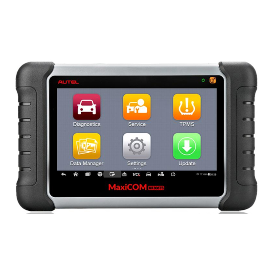
Slide the Lock icon to the left to enter the MaxiCOM Job Menu or slide to the right to unlock. Figure 3-1 Sample MaxiCOM MK808TS Job Menu Application Buttons Locator and Navigation Buttons... - Page 19 NOTE The tablet screen is locked by default when first powered on. It is recommended to lock the screen to protect the information in the system and reduce the power consumption. The touch screen navigation is menu driven enabling quickly access to functions and features by tapping on options headings and answering dialog windows.
- Page 20 See Quick Link on page 149 for details. Provides quick search for the supported Function functions and vehicles of Autel diagnostic tools. Viewer Function Viewer on page 150 for details. Locator and Navigation Buttons Operations of the Navigation buttons at the bottom of the screen are...
- Page 21 Button Name Description Back Returns to the previous screen. Android Returns to Android System’s Home screen. Home Displays a list of applications that are currently in use. Tap an app icon to launch. Recent Apps To remove an app, swipe it to the top or bottom.
-
Page 22: Powering Down
NOTE The shortcuts buttons will be highlighted when enabled, and dimmed when disabled. Table 3-3 System Status Icons Button Name Description Calculator Launches calculator when pressed. Clock Launches clock when pressed. Enables/disables BT when pressed. Wi-Fi Enables/disables Wi-Fi when pressed. Enables/disables Airplane Mode when Airplane Mode... -
Page 23: Diagnostics
Diagnostics The Diagnostics application can retrieve ECU information, read & erase DTCs, and view live data. The Diagnostics application can access the electronic control unit (ECU) for various vehicle control systems, including engine, transmission, antilock brake system (ABS), airbag system (SRS). Establishing Vehicle Communication The Diagnostics operations require connecting the MK808TS Diagnostic Platform to the test vehicle through the MaxiVCI Mini. - Page 24 VCI Connection The MaxiVCI Mini Power LED will light solid green when properly connected to the vehicle and ready to establish communication with the tablet. The wireless diagnostic interface MaxiVCI Mini supports 2 communication methods with the tablet, wireless BT and USB. BT Connection BT pairing is recommended as the first choice for the communication between the tablet and the MaxiVCI Mini.
-
Page 25: Getting Started
Check if the MaxiVCI Mini is properly positioned. Check if the Connection LED on the MaxiVCI Mini is illuminated for BT or USB. In case of BT connection, check if the network is configured correctly, or if the right MaxiVCI Mini has been paired up with the tablet. - Page 26 When the tablet device is properly connected to the vehicle, the platform is ready to start vehicle diagnosis. Tap on the Diagnostics application button on the MaxiCOM MK808TS Job Menu to access the Vehicle Menu. Figure 4-1 Sample Vehicle Menu...
-
Page 27: Vehicle Identification
Displays the USA vehicle menu. Displays the European vehicle menu. Europe Displays the Asian vehicle menu. Asia Search Searches for a specific vehicle make. Cancel Exits the search screen or cancels an operation. Vehicle Manufacturer Buttons To begin, select the manufacturer button of the test vehicle, followed by the vehicle mode and year. - Page 28 Tap the VIN Scan button on the top toolbar to open the dropdown list. Figure 4-2 Sample Auto VIN Screen Select Auto Detect. Once the test vehicle is identified, the screen will display the vehicle VIN. Tap OK at the bottom right to confirm the vehicle VIN.
- Page 29 Figure 4-4 Sample Vehicle Profile Screen The tool establishes communication with the vehicle and reads the control unit information. Choose Auto Scan to scan all the test vehicles’ available systems or tap Control Unit to access a specific system to diagnose. Figure 4-5 Sample Diagnostic Screen Manual VIN Input For vehicles not supporting the Auto VIN Scan function, you may manually...
- Page 30 Menu. The Vehicle Menu displays. Tap the VIN Scan button on the top toolbar to open the dropdown list. Select Manual Input. Tap the input box and enter the correct VIN. Figure 4-6 Sample Diagnostic Screen Tap Done. Once the vehicle is identified, the Vehicle Diagnostics screen displays.
-
Page 31: Navigation
Figure 4-7 Sample Selection Screen To perform Automatic Selection Tap the Diagnostics application button from the MaxiCOM Job Menu. The Vehicle Menu displays. Tap the manufacturer button of the test vehicle. Tap Automatic Selection and the VIN information will be acquired automatically. - Page 32 Diagnostics Screen Layout Figure 4-8 Sample Diagnostics Screen The diagnostic screens typically include four sections. Diagnostics Toolbar Status Information Bar Main Section Functional Buttons Diagnostics Toolbar The Diagnostics Toolbar contains a number of buttons such as print and save. The table below provides a brief description of the operations of the Diagnostics Toolbar buttons.
- Page 33 Button Name Description Prints a copy of the displayed data. See Printing Print Setting on page 105 for details. Help Displays operations instructions or tips. Saves the current page. See Data Manager Save page 98 for details. Records the communication data and ECU Data information of the test vehicle.
- Page 34 Status Information Bar The Status Information Bar at the top of the Main Section displays the following items: Menu Title – displays the menu heading of the Main Section. Voltage Icon – displays the vehicle’s voltage status. Main Section The Main Section of the screen varies according to the stage of operations. The Main Section can display vehicle identification selections, the main menu, test data, messages, instructions and other diagnostic information.
-
Page 35: Diagnosis
Error Messages Error messages display when a system or procedural error has occurred. Examples of possible errors include a disconnection or communication interruption. Making Selections The Diagnostics application is a menu driven program that presents a series of choices. As a selection is made, the next menu in the series displays. Each selection narrows the focus and leads to the desired test. - Page 36 Figure 4-9 Sample Auto Scan Operation Screen Navigation Bar Main Section Functional Buttons Navigation Bar List Tab – displays the scanned data in list format. Progress Bar – indicates the test progress. Main Section Column 1 – displays the sequence numbers. Column 2 –...
- Page 37 Column 4 – to perform further diagnosis or testing on a specific system item, ○ tap the > button to the right of that item. A Function Menu screen will display. Functional Buttons A brief description of the Auto Scan’s Functional Buttons’ operations are displayed in the table below.
- Page 38 Figure 4-10 Sample Function Menu The Function Menu options vary slightly for different vehicles. The function menu may include: ECU Information – provides the retrieved ECU information in detail. An information screen opens upon selection. Read Codes – displays detailed information of DTC records retrieved ...
- Page 39 ECU Information This function retrieves and displays the specific information for the tested control unit, including unit type, version numbers and other specifications. The sample ECU Information screen displays as below: Figure 4-11 Sample ECU Information Screen Diagnostics Toolbar Buttons – see Table 4-2 Diagnostics Toolbar Buttons on page 25 for detailed descriptions of the operations for each...
- Page 40 Figure 4-12 Sample Read Codes Screen Diagnostics Toolbar Buttons – see Table 4-2 Diagnostics Toolbar Buttons on page 25 for detailed descriptions of the operations for each button. Main Section Code Column – displays the retrieved codes from the vehicle. ...
- Page 41 To erase codes Tap Erase Codes from the Function Menu. A warning message displays to advise of data loss if this function is completed. Tap Yes to continue. A confirming screen displays when the operation is successfully done. Tap No to exit. Tap ESC on the confirming screen to exit Erase Codes.
- Page 42 operations for each button. Main Section Name Column – displays the parameter names. Check Box – tap the check box on the left side of the parameter name to make item selection. Tap the check box again to deselect the item. Drop-down Button –...
- Page 43 When this mode is selected, three control buttons display on the right side of the parameter item for manipulation of display status. Text Button – resumes Text Display Mode. Scale Button – changes the scale values that are displayed below ...
- Page 44 The operations of available functional buttons on Live Data screen are described below: Back – returns to the previous screen or exits the function. Record – starts recording the retrieved live data; the recorded data is then stored as a video clip in the Data Manager application for future review.
- Page 45 Figure 4-14 Sample Setting Mode in Live Data There are four navigation buttons on top of the Setting mode screen. Selected Button – displays the configuration screen to set the threshold values, an upper limit and a lower limit, for triggering the buzzer alarm.
- Page 46 Tap Done to save the setting and return to the Live Data screen; or tap Cancel to exit without saving. If the threshold limits are successfully set, two horizontal lines will display on each of the data graphs (when Waveform Graph Mode is applied) to indicate the alarm point.
-
Page 47: Generic Obd Ii Operations
Done Button - confirms and saves the setting, and returns to the Live Data screen. Cancel Button – cancels the setting operation, and returns to the Live Data screen. Generic OBD II Operations This option presents a quick way to check for DTCs, isolate the cause of an illuminated malfunction indicator lamp (MIL), check monitor status prior to emissions certification testing, verify repairs, and perform a number of other services that are emissions-related. - Page 48 Figure 4-15 Sample OBD II Diagnostic Menu NOTE ○ Tapping the i button displayed beside the function name opens a bubble with additional function information. Select a function option to continue. DTC & FFD I/M Readiness Live Data ...
- Page 49 item when the Freeze Frame data is available for viewing. Tap Clear DTC to erase codes. Figure 4-16 Sample DTC & FFD Screen Stored Codes Stored codes are the current emission-related DTCs from the ECM of the vehicle. OBD II/EOBD Codes have a priority according to their emission severity, with higher priority codes overwriting lower priority codes.
- Page 50 Freeze Frame Typically, the stored frame is the last DTC that occurred. Certain DTCs that have a greater impact on vehicle emission, have a higher priority. In these cases, the top prioritized DTC is the one for which the freeze frame records are retained.
-
Page 51: Exiting Diagnostics
Component Test This service enables bi-directional control of the ECM so that the diagnostic tool is able to transmit control commands to operate the vehicle systems. This function is useful in determining whether the ECM responds to a command well. Vehicle Information The option displays the vehicle identification number (VIN), the calibration identification, and the calibration verification number (CVN), and other... - Page 52 toolbar; or tap the Back button on the navigation bar at the bottom of the screen. Or tap the Home button on the diagnostics toolbar to exit the application directly and go back to the MaxiCOM Job Menu. Now, the Diagnostics application is no longer communicating with the vehicle and it is safe to open other MaxiCOM applications, or exit the MaxiCOM Diagnostic System and return to the Android System’s Home screen.
-
Page 53: Service
Service The Service section is specially designed to provide quick access to the vehicle systems for various scheduled service and maintenance tasks. The typical service operation screen is a series of menu driven executive commands. Follow on-screen instructions to select appropriate execution options, enter correct values or data, and perform necessary actions. - Page 54 NOTE All required work must be carried out before the service indicators are reset. Failure to do so may result in incorrect service values and cause DTCs to be stored by the relevant control module. NOTE For some vehicles, the scan tool can reset additional service lights such as maintenance cycle and service interval.
- Page 55 Follow the step-by-step on-screen instruction to complete the service. Using CBS Reset UDS as an example. Tap CBS Reset UDS on the Oil Reset function list to start the operation. The screen will display the date and time and ask for confirmation.
-
Page 56: Electronic Parking Brake (Epb) Service
Figure 5-4 Sample Oil Reset Service Screen 3 When the reset is done, the availability would display as 100%. Tap ESC to exit. Electronic Parking Brake (EPB) Service This function has a multitude of usages to maintain the electronic braking system safely and effectively. - Page 57 NOTE Autel accepts no responsibility for any accident or injury arising from the maintenance of the Electronic Parking Brake system. To perform EPB functions Tap the Service application button from the MaxiCOM Job Menu. Tap EPB button. The vehicle manufacturer selection screen will display.
- Page 58 Figure 5-6 Sample EMF Start-up Screen 1 Tap Continue to proceed with this service function or the Back button at the bottom left to exit. Tap on completed action to continue. Figure 5-7 Sample EMF Start-up Screen 2 The following screen will display a message to advise that the fault memory of the parking brake control unit will be deleted.
- Page 59 Figure 5-8 Sample EMF Start-up Screen 3 Follow the on-screen instructions to pull the parking brake button and wait for approximately three seconds until the parking brake is set. When the operation is successfully completed, a “Completed successfully” message will display on the screen, press OK to exit. Parking Brake: Workshop Mode This service is used to activate and deactivate the so-called installation position for the Automatic Hold brake.
-
Page 60: Battery Management System (Bms) Service
Battery Management System (BMS) Service The Battery Management System (BMS) allows the scan tool to evaluate the battery charge state, monitor the close-circuit current, register the battery replacement, and activate the rest state of the vehicle. NOTE This function is not supported by all vehicles. The screens shown in this section are examples. - Page 61 Tap the Service application button from the MaxiCOM Job Menu. Tap BMS button and wait for the vehicle manufacturer screen. You can tap VIN Scan or the vehicle make to acquire vehicle VIN information and tap Yes to confirm. See Vehicle Identification page 20 for detail.
- Page 62 Read carefully the complete information and press Continue to continue. Figure 5-11 Sample BMS Screen 3 Check the battery capacity and the battery replacement information on the screen. Tap on the corresponding function (function one in our example) to return to the selection screen or press the function two to end the service function.
- Page 63 Figure 5-13 Sample BMS Screen 4 Read carefully the information on the screen and scroll through list to view all functions. There are four functions listed: Figure 5-14 Sample BMS Screen 5 Enter battery replacement: Same capacity Enter battery replacement: Different capacity Enter battery replacement: Changing from the normal lead-acid battery (white housing) to AGM battery (black housing)
- Page 64 End service function. Figure 5-15 Sample BMS Screen 6 Take the first function as an example. Read carefully the information on the screen and tap Yes to continue. Follow the on-screen instructions to input the data matrix code of the newly installed battery which should be on the label of the battery.
-
Page 65: Steering Angle Sensor (Sas) Service
Figure 5-17 Sample BMS Screen 8 Steering Angle Sensor (SAS) Service Steering Angle Sensor Calibration permanently stores the current steering wheel position as the straight-ahead position in the steering angle sensor EEPROM. Therefore, the front wheels and the steering wheel must be set exactly to the straight-ahead position before calibration. - Page 66 NOTE AUTEL accepts no responsibility for any accident or injury arising from servicing the SAS system. When interpreting DTCs retrieved from the vehicle, always follow the manufacturer’s recommendation for repair. All software screens shown in this manual are examples, actual test screens may vary for each test vehicle.
- Page 67 Tap Steering Angle Sensor Calibration from the SAS function menu to enter the function screen. Follow the on-screen instructions to set the ignition on/off as guided. The vehicle battery voltage signal should be in the range 12.5 – 13.5 volts to proceed with this service, otherwise the scan tablet will display a warning message.
-
Page 68: Diesel Particle Filter (Dpf) Service
Diesel Particle Filter (DPF) Service The Diesel Particle Filter (DPF) function manages DPF regeneration, DPF component replacement teach-in and DPF teach-in after replacing the engine control unit. The ECM monitors driving style and selects a suitable time to employ regeneration. Cars driven a lot at idling speed and low load will attempt to regenerate earlier than cars driven more with high load and speed. - Page 69 vehicle while the other person observes the screen on the Tool. Do not attempt to drive and observe the scan tool at the same time. This is dangerous and puts your life and the lives of other motors and pedestrians at risk. Figure 5-21 Sample DPF Service Function Menu Starting Basic Inspection Quantity This function enables start fuel delivery matching.
- Page 70 Figure 5-22 Sample Starting Basic Inspection Quantity [1] Enter New Value for Adjustment From the Starting Basic Inspection Quantity menu, tap [1] and the screen displays as below. Figure 5-23 Sample Enter New Value Screen After entering the value, tap OK to save the value to the tool. Tap ESC to exit the operation.
- Page 71 NOTE The data you input should be in the range given. If the input data is out of range, the tool will display a warning message “Permissible adjustment range exceeded.” [2] Reset Adjustment to 0 Once the [2] is tapped, the tool will automatically reset the value to zero. [3]/[4] Store Data and Exit When the fuel delivery rate adjustment is completed, tap [3] to store the new value in the control units;...
- Page 72 From the Injection Rate menu, tap [1] and the screen displays as below. Figure 5-25 Sample Enter Value Screen NOTE The data you input should be in given range. If the input data is out of range, the tool will display a warning message “Permissible adjustment range exceeded.”...
- Page 73 Follow the on-screen instructions to tap on the corresponding number [1] [2] [3] [4] to enter the new value for the cylinder, restore the old value, and exit after finish the function. Particle Filter Regeneration This function is used to perform the particle filter regeneration. Tap Particle filter regeneration from the service functions menu.
- Page 74 A series of instruction screens display for users to perform the particle filter regeneration step by step. Follow the onscreen instructions and tap OK button until the tool displays the regeneration status as below. Figure 5-27 Sample Regeneration Status Screen When the particle filter regeneration is complete, confirm to exit the display.
- Page 75 During the regeneration phase and with the engine running, it can also occur that the display for “Regeneration active” jumps to “Regeneration not active”. This behavior can be seen exclusively with the vehicle stationary with the engine. Particle Filter Test It is advisable to carry out a series of particle filter tests as a result of constant DPF regeneration, such as checking oil level, oil change interval for diesel contamination, swirl flaps, backpressure sensors and particle filter...
-
Page 76: Immobilizer (Immo) Service
The tool shows a list of particle filter test. Select the corresponding number button to perform the desired test [1] [2] [3] [4] [5]. [1] Visual Inspection of Engine Oil [2] Visual Inspection of Particulate Filter [3] Function Check or Swirl Flaps [4] Exhaust Backpressure Test [5] Actual/Target Value Check-Mass Air Flow Sensor Immobilizer (IMMO) Service... - Page 77 MaxiCOM Job Menu. Tap Automatic Selection or Manual Selection to acquire vehicle VIN information and tap Yes to confirm. Tap Erase/Program all key fobs in the IMMO function list once displayed. The list may vary by test vehicle. NOTE To complete key fob programming, the Security Code will need to be required.
- Page 78 Figure 5-31 Sample Program Key FOB Screen...
-
Page 79: Tpms
TPMS MK808TS provides the most comprehensive TPMS services for technicians to quickly solve TPMS related problems in the shortest time and with the highest efficiency. Getting Started TPMS Service Menu Layout Tap TPMS on the MaxiTPMS Job Menu. The screen then opens the TPMS Vehicle Menu. -
Page 80: Vehicle Selection
TPMS Service Access Methods OEM Part No. Refer to TPMS by OEM Part No. on page 93 for details. Vehicle Selection Select the required manufacturer and follow the onscreen instructions to select vehicle information step by step to start a TPMS service session. Navigation Buttons Refer to Table 3-2 Locator and Navigation Buttons... - Page 81 Figure 6-3 Sample Vehicle Model Selection Figure 6-4 Sample Vehicle Year Selection The following screen may display for vehicles using Indirect TPMS.
- Page 82 Figure 6-5 Sample Indirect TPMS Selection Screen For indirect TPMS vehicle, only the Relearn function is supported. Tap the vehicle year information button, in the case of the above screen – 2008/08-2017/01 (indirect), to display the Relearn Procedure. Follow the instructions to complete the operation.
- Page 83 Figure 6-7 Sample TPMS Service Screen Top Toolbar Buttons Navigation Tab Main Section Functional Buttons Top Toolbar Buttons The top toolbar contains a number of buttons including print and save. See Table 4-1 Top Toolbar Buttons on page 19 for details. Navigation Tab The navigation tab at the top of the Main Section screen contains the following items:...
-
Page 84: Tpms Check
The information of the test vehicle is displayed to the left of the four tabs. The VCI connection status and the battery level of the test vehicle are displayed to the right of the four tabs. NOTE Not all vehicles support Diagnosis function. If the selected vehicle model does not support Diagnosis, this tab will not appear on the screen. - Page 85 NOTE The default check order on the tablet is FL, FR, RR, RL and the wheel positions are associated with the rows in the right table. If you select FR in the right table, the cursor on the left vehicle icon will be automatically moved to FR position.
-
Page 86: Tpms Diagnosis
Successful TPMS sensor successfully Sensor Read & (Green) activated and decoded and the Low Battery battery level of the sensor is low. If the search period expires and no sensor is activated or decoded, the sensor may be mounted incorrectly or cannot function. The Failed Sensor table on the right side of the Read... - Page 87 Figure 6-10 Sample Diagnosis Screen 1 If the OBD function is supported by the test vehicle, the sensor ID saved in the TPMS ECU will be retrieved and displayed on the screen with an OBD mark before it when the communication is completed. If the sensor ID retrieved from sensor activation is the same as the ID saved in the ECU, the trigger mark ( ) and OBD mark (...
- Page 88 Figure 6-11 Sample Diagnosis Screen 2 Details If Data Trouble Codes (DTCs) are present in the TPMS ECU, a yellow hazard icon displays in the DTC column and the details button is available. Tap details in the DTC column to view the detailed information. Figure 6-12 Sample DTCs Screen In this screen, the detailed fault definition will be displayed.
- Page 89 Figure 6-13 Sample No DTC Screen Retry Tap Retry to establish communication with ECU again and to retrieve sensor IDs and DTCs present in the ECU. Live Data Tap Live Data to view the data stream of the sensor information. Figure 6-14 Sample Live Data Screen The Live Data screen displays all parameters be default.
-
Page 90: Sensor Programming
Special Functions Tap this button to open a screen of Active Test. Figure 6-15 Sample Special Functions Screen Tap button to initiate desired vehicle lamp function list. Sensor Programming The Programming function allows users to program the sensor data to the MX-Sensor and replace faulty sensor with low battery life or the one that is not functioning. - Page 91 The sensor IDs retrieved from sensor activation and TPMS ECU will automatically appear on the left column of the table on the screen with the trigger and OBD marks before them. If the OBD function is not supported by the test vehicle and the sensor ID saved in the ECU cannot be retrieved, the Programming screen appears as below.
- Page 92 Figure 6-18 Sample Copy by Activation Confirmation Screen A window will display for your confirmation. Tap OK to program, or tap Cancel to quit the operation. Figure 6-19 Sample Copy by Activation Screen...
- Page 93 Figure 6-20 Sample Copy by Activation Complete Screen When the programming is complete, the programmed ID will display in the column to the right of the wheel designation. In the pictured example, the new ID is displayed to the right of the FL column. By using Copy by Activation, the sensor ID that is retrieved from activated sensor is programmed to the new MX-Sensor.
- Page 94 Select one sensor position and place a MX-Sensor near the TPMS antenna of the tablet (the top right corner), and then tap Copy by OBD to program the new MX-Sensor. Figure 6-21 Sample Copy by OBD Screen When the programming is complete, the programmed ID will display in the column to the right of the wheel designation.
- Page 95 Select one sensor position and place a MX-Sensor near the TPMS antenna of the tablet (the top right corner), and then tap Copy by Input to program the new MX-Sensor. Figure 6-22 Sample Copy by Input Screen Tap Copy by Input. When the input displays, enter the ID of the original sensor.
-
Page 96: Tpms Relearn
A random ID will be created for the MX-Sensor. This new ID differs from the ID stored in the TPMS ECU, therefore the sensor will have to be Relearned to the TPMS ECU. Figure 6-23 Sample Auto Create Screen TPMS Relearn This function is used to write the newly programmed sensor IDs into the vehicle ECU for sensor recognition. - Page 97 Figure 6-24 Sample Stationary Relearn Screen 1 Then follow the Relearn Procedure to perform Stationary Relearn. Figure 6-25 Sample Stationary Relearn Screen 2 Active Relearn For some vehicles, the Relearn function can be completed by driving. Refer to the on-screen Relearn Procedure for the exact details of the process.
- Page 98 Figure 6-26 Sample Active Relearn Screen 1 Figure 6-27 Sample Active Relearn Screen 2 OBD II Relearn OBD II Relearn The OBD II Relearn function allows the MK808TS tablet to directly write the TPMS sensor IDs to the TPMS module. NOTE Not all the vehicles support the OBD II Relearn.
- Page 99 To perform the Relearn, activate all four sensors. Figure 6-28 Sample OBD II Relearn Screen 1 Figure 6-29 Sample OBD II Relearn Screen 2 OBD II Assisted Relearn The MK808TS tablet also provides OBD II Assisted Relearn functions. Since the MK808TS tablet wirelessly communicates with vehicles, it can be used to trigger wheel-mounted sensors while still being connected with the vehicle eliminating the need for a second tool.
-
Page 100: Tpms By Oem Part No
TPMS by OEM Part No. If the sensor’s OEM part number is known, this function is an efficient method to activate and program MX-Sensors. Application Scenarios The following are two typical scenarios in which this method is ideal. In the workshop If the mounted sensor is faulty and the part number is known to the technician, the technician can use this method to check the original sensor, and then write the information that was retrieved into a new MX-Sensor via... - Page 101 Figure 6-30 Sample OEM Part No. Screen Or tap the search box on the top right side of the screen to enter the part number. A soft keyboard will display as below. Enter the OEM Part No. in the search box at the top right corner to complete the operation. to change the keys to numbers, tap to change the keys to letters.
- Page 102 When a specific OEM part No. is selected, the screen will display as pictured below. 6-32 Sample OEM Part No. Service Menu NOTE Only sensor Check and Programming functions are available with the OEM Part No function. The Diagnosis and Relearn functions can only be accessed by selecting a vehicle on the TPMS service menu.
- Page 103 Figure 6-33 Sample Check Screen via OEM Part No. Programming The programming function is used to program the sensor data to the MX-Sensor and replace the faulty sensor (poor battery life or malfunction). There are three options available when programming MX-Sensor using the OEM Part No.
- Page 104 The Product Serial Number (PSN) Code, which is printed on the MX-Sensor, acts as reference to identify the corresponding sensor ID. This can be especially useful when programming multiple MX-Sensors. Support Support will display the correct vehicle types for the selected OEM part number.
-
Page 105: Data Manager
Data Manager The Data Manager application is used to store, print, and review the saved files. Most operations are controlled through the toolbar. Selecting the Data Manager application opens the file system menu. Different file types are sorted separately under different options, there are six types of information files to be viewed or played back. - Page 106 Figure 7-2 Sample Image Screen Toolbar Buttons – used to edit, print and delete the image files. See the following table for detailed information. Main Section – displays the stored images. Table 7-1 Toolbar Buttons in Image Screen Button Name Description Back Returns to the previous screen.
- Page 107 > Support & Updates > Firmware & Downloads > UPDATE CLIENT, and install to your PC. The Maxi PC Suite consists of Autel Printer, MaxiSys Pinter and PC Suite. Double click on Setup.exe item. Select the installation language and the printer driver installation wizard will load momentarily.
- Page 108 images, the selected thumbnail displays a tick icon at the bottom right corner. Tap the Delete button, and then Delete Selected, then the selected images will be deleted. PDF Files The PDF section stores and displays all saved data PDF files. Select a PDF file from the database to display.
- Page 109 Use the Navigation Toolbar buttons to playback the record data from frame to frame. Tap Back to exit data playback. Apps Uninstall This section manages the firmware applications installed on the MaxiCOM Diagnostics System. Select this section to open a management screen, on which you all the available vehicle diagnostic application can be reviewed.
-
Page 110: Settings
Settings Tap the Settings button to adjust the default setting and view information about the MaxiCOM system. There are seven options available for the MaxiCOM system settings: Unit Language Printing Setting Notification Center Auto Update ... -
Page 111: Language
Figure 8-1 Sample Unit Setting Screen Language This option allows you to adjust the display language for the MaxiCOM system. To adjust the language setting Tap the Settings application on the MaxiCOM Job Menu. Tap the Language option on the left column. Figure 8-2 Sample Language Setting Screen Select the appropriate language. -
Page 112: Printing Setting
Tap the Home button on the top left corner to return to the MaxiCOM Job Menu, or tap another setting to adjust. Printing Setting Configure this option to enable the tablet to print through a specified Wi-Fi network connection. To setup the printer connection Tap the Settings application on the MaxiCOM Job Menu. - Page 113 Follow the instructions below to realize this function. To install the printer driver program to a computer Download the Maxi PC Suite from www.autel.com and install to your PC. Double click on Setup.exe item. Select the installation language and the wizard will load momentarily.
-
Page 114: Notification Center
Notification Center This option allows you to turn the Notification Center function on or off. The Notification Center function configures the MaxiCOM tablet to receive regular on-line messages from the server for system update notifications or other service information via the Internet. It is highly recommended to keep this function ON all the time, to ensure notifications of updates are received. -
Page 115: Auto Update
Tap a specific message to launch the corresponding application. For example, tap on an Update notification message and the Update application will launch. Auto Update The Auto Update allows the tool to automatically update the OS, the MaxiCOM system, and the Vehicle coverage software. Each can be configured to update automatically at specified times. -
Page 116: System Settings
Figure 8-6 Sample Set Time Screen NOTE The tool must be connected to the Internet at the time download is scheduled. System Settings Access the Android system setting interface to adjust background system settings including wireless and network settings, sound and display screen settings and system security settings. -
Page 117: About
Figure 8-7 Sample System Settings Screen Tap the App Switcher option on the left column. Check the box beside “Always show the App Switcher” on the right side of the screen, then the App Switcher icon will display. Short pressing the App Switcher icon opens a control panel: ... - Page 118 Tap the Home button on the top left corner to return to the MaxiCOM Job Menu or select another setting to adjust. Figure 8-8 Sample About Screen...
-
Page 119: Update
Update This chapter describes the update operation for both the MK808TS tablet and the MaxiVCI Mini. The software and firmware updates of the tablet can be completed on the tablet via Internet, while the updates for MaxiVCI Mini can be completed either via the connection with the tablet or via the connection with a PC. - Page 120 Figure 9-1 Sample Update Screen Navigation and Controls Home Button – returns to the MaxiCOM Job Menu. Update All – updates all available updates. Diagnostics Tab – displays all available vehicle diagnostic software. TPMS Tab - displays all available TPMS service software for vehicles.
- Page 121 ○ changes to the software operation or capabilities. Tap button to open an information screen to view more details, and tap the dim area around to close the window. Right Column – according to the operation status of each software ...
-
Page 122: Maxivci Mini Update
VCI software if available. Update via PC Down the Maxi PC Suite from www.autel.com > Support & Updates > Firmware Downloads > Update Client, and install it onto your PC. Using a USB cable, connect the MaxiVCI Mini to a PC. -
Page 123: Vci Manager
VCI Manager This application pairs the tablet with the MaxiVCI Mini, checks the communication status and update the VCI software and TPMS service firmware. Figure 10-1 Sample VCI Manager Screen Connection Mode – there are three connection modes available for selection. -
Page 124: Bt Pairing
BT Pairing The MaxiVCI Mini needs to be connected to a vehicle, so that it is powered during the synchronization procedure. Ensure the tablet has sufficient battery life or is connected to an external power supply. To pair the MaxiVCI Mini with the Tablet Power on the tablet. -
Page 125: Programmer Update
Programmer Update Coming soon. -
Page 126: Shop Manager
Shop Manager The Shop Manager application manages the workshop information, customer information records, and test vehicle history records. There are three main functions available: Vehicle History Workshop Information Customer Manager The operations of these functions of the Shop Manager application are mainly manipulated by the toolbar buttons, which are listed and described in the table below: Table 11-1 Top Toolbar Buttons in Shop Manager... -
Page 127: Vehicle History
Button Name Description Opens a note form. Audio, video, image and text History Notes files may be attached. Displays Vehicle History which Vehicle History corresponding test vehicle records. Done Completes editing and saves the file. Vehicle History This function stores test vehicle history records, including vehicle information and the retrieved DTCs from previous diagnostic sessions. - Page 128 information of the recorded test vehicle and tap the Diagnostics button on the upper right corner. The vehicle’s Diagnostics screen displays. Now a new diagnostic session is activated, see Diagnostics on page 16 for detailed instructions on vehicle diagnostic operations. Historical Test Record The Historical Test record sheet is a detailed data form that includes general vehicle information such as vehicle year, make and model.
-
Page 129: Workshop Information
NOTE The vehicle VIN number, or license and the customer information account are correlated by default. Adding one of the information will automatically associate the other item in the record sheet, provided that the later one exists. Tap Add to Customer to supplement the Historical Test record sheet to an existing customer account, or add a new associated account with the test vehicle record. -
Page 130: Customer Manager
Tap Done to save the updated workshop information sheet, or tap Cancel to exit without saving. Customer Manager Use the Customer Manager function to create and edit customer accounts and correlate with the associated test vehicle history records. To create a customer account Tap the Shop Manager application on the MaxiCOM Job Menu. - Page 131 To delete a customer account Tap the Shop Manager application on the MaxiCOM Job Menu. Select Customer Manager and select a customer account by tapping the corresponding name card. A Customer Information sheet displays. Tap the Edit button on the top toolbar to start editing. Tap the Delete Customer Information button.
- Page 132 11-4 Sample History Notes Screen Functional Buttons – navigates and makes various controls of the function. Main Section – displays the note list on the left column and the detail information of the selected note on the right column. Table 11-2 Function Buttons in History Notes Button Name Description...
- Page 133 Tap on the Title bar to input a note title. Tap on the blank space below to edit a text note or remark. Select a function button on the top to add files in any form you choose. Tap Save to save the note; tap Discard or Cancel to exit without saving.
-
Page 134: Academy
Academy Autel provides various tutorial articles and technical bulletins produced by top-notch technicians and product experts. Please view the materials that are saved on the tablet or view technical articles from our online forum by clicking the links displayed under this application. -
Page 135: Remote Desk
The Remote Desk application launches the TeamViewer Quick Support program, which is a simple, fast and secure remote control screen. You can use the application to receive ad-hoc remote support from Autel’s support center, colleagues, or friends, by allowing them to control your MaxiCOM tablet on their PC via the TeamViewer software. - Page 136 shown. Your partner must install the Remote Control software to his/her computer by downloading the TeamViewer full version program online (http://www.teamviewer.com), and then start the software on his/her computer at the same time, in order to provide support and take control of the tablet remotely. Provide your ID to the partner, and wait for him/her to send you a remote control request.
-
Page 137: Maxifix
MaxiFix The MaxiFix application launches the on-line troubleshooter database, which not only provides you virtually all common diagnostic trouble code (DTC) database for most vehicles, but also serves as a forum allowing you to network with other MaxiCOM users, and gives you access to a vast database of repair and diagnostic tips along with proven filed fixes. - Page 138 The Main Screen – located at the center of the screen displaying content based on the vehicle attributes and keywords specified. The tabs on the main screen vary in accordance with the section selected on the Navigation Menu, allowing you to switch between functions. The Navigation Menu –...
- Page 139 After completing the vehicle selection procedure, the identified vehicle is shown on the Header. Terminology MaxiFix Tip A MaxiFix Tip provides practical information of real fix of a specific vehicle repair issue with detailed descriptions. It is combined with proven fix and vehicle specific data, and filed into an all-in-one information source to provide you with quick and easy repair solutions.
-
Page 140: Operations
Real Fix Tips – provides repair tips from actual shop practices and are presented in an easy to understand Complaint, Cause, Correction format. If you still can’t find the information you want, you can ask the MaxiFix community for help by clicking Ask on the Navigation Menu at the bottom of the screen. - Page 141 Home Home is the first option on the Navigation Menu at the bottom of the screen. Tapping it opens your MaxiFix home page. There is a list of questions posted on the community, and you can scroll down the page to the bottom and view more questions by tapping View More.
- Page 142 Marked Posts – opens a list with links to Tips and discussions that you are actively participating in. My Profile – allows you to view your Autel account information including: your Autel ID, personal information, MaxiFix score, phone number and...
- Page 143 register time, and edit your portrait. Vehicle Preference –used to set up a list of preferred vehicles. The preferred list allows you to limit the choices that displayed on the Select Vehicle list to specific years, and makes. Click Set Year or Set Make to set your preferred models.
- Page 144 View Profile Information You can view your personal profile by clicking on your account ID or “My Profile” in My MaxiFix section or edit portrait where applicable, and visit other community members’ profile by clicking their portrait. Information included in your profile determines how you are presented to the community, and what type of information will be sent to you from the community.
- Page 145 Answers can only be rated by the MaxiFix member who asked the question. Close a Question When a repair question that you've posted to the community is resolved, you are encouraged to write down the case as a way to share a good solution.
- Page 146 comment window. To allow the administrator to respond to your question or issue, the following information should be provided: Your name A contact email address A contact phone number...
-
Page 147: Support
On the Sign In page, input your account ID and other information to log in, if you already have an account. If you are a new member to Autel and do not have an account, click the Create Autel ID button on the left side. -
Page 148: Support Screen Layout
Support Screen Layout The Support application interface is navigated via four simple buttons on the top navigation bar, operation of each is described below in turn from left to right: Home Button – returns to the MaxiCOM Job Menu. Back –... -
Page 149: User Complaint
The User Info and Device Info are both included under the Personal Info section. User Info - displays detailed information of your registered on-line Autel account, such as your Autel ID, Name, Address and other contact information, etc. Device Info – displays the registered product information, including the ... - Page 150 Figure 15-2 Sample Complaint Screen The User Complaint screen consists of two parts. Option Bar Period Filter – displays only the complaint records within the defined period on the list. Status Filter – displays the corresponding complaint records according to the selected case status.
- Page 151 Select the required processing time on the last section according to the urgency of the case. Tap Submit to send the completed form to Autel’s online service center, or tap Reset to refill it. The submitted complaints will be carefully read and handled by the service personnel, and the respond speed may depend on the processing time you’ve...
-
Page 152: Data Logging
attaching file. Tap Submit to post the reply. Tap the States selection drop-down menu to reset a case state. Tap the Update button to commit the newest update. Data Logging The Data Logging section keeps records of all sent or unsent (saved) data loggings on the diagnostic system. -
Page 153: Communities
Forums on Autel’s official website www.autel.com, where you are allowed to discuss technical topics or share information with, as well as ask for technical advices or offer technical supports to all other members in Autel’s online support communities. Figure 15-4 Sample Communities Home Screen ... - Page 154 pinpoint the topics you are most interested with. ○ Tap the > button on the right side of the topic item to view the discussion. The posts contents are displayed. Browse through all the posts by sliding the screen up and down. Tap Go to original post when reaching the end of the discussion to return to the first post.
-
Page 155: Training Channels
list. Training Channels The Training section provides quick links to Autel’s online video accounts. Select a video channel by the language to see all the available online tutorial videos from Autel for various technical supports, such as product usage techniques and vehicle diagnostics practice. -
Page 156: Quick Link
Quick Link The Quick Link application provides convenient access to Autel’s official website and to additional in automotive service sites. Figure 16-1 Sample Quick Link Screen To open a quick link Tap the Quick Link application on the MaxiCOM Job Menu. The Quick Link application screen displays. -
Page 157: Function Viewer
Function Viewer The Function Viewer allows you to search the functions supported by our tools and the software version information. There are two ways of searching, either by searching the tool and the vehicle or searching the functions. To Search by the vehicle Tap the Function Viewer application on the MaxiCOM Job Menu. - Page 158 Figure 17-2 Sample Function Viewer Screen 2 Search by the functions Tap the Function Viewer application on the MaxiCOM Job Menu. The Function Viewer application screen displays. Tap the tool name on the top left to drop down the tool list, tap the one you want to search.
-
Page 159: Maintenance And Service
Maintenance and Service Maintenance Instructions Follow these guidelines to maintain your tool and ensure its optimum performance. Use a soft cloth and alcohol or a mild window cleaner to clean the touch screen of the tablet. Do not use any abrasive cleansers, detergent, or automotive chemicals to the tablet. -
Page 160: Troubleshooting Checklist
Your device may have not been connected to the charger properly. Check the connector. NOTE If your problems persist, please contact Autel’s technical support personnel or your local selling agent. About Battery Usage Your tablet is powered by a built-in Lithium-ion Polymer battery. This means that, unlike other forms of battery technology, you can recharge your battery while some charge remains without reducing your tablet’s autonomy due to... -
Page 161: Service Procedures
explosion. Do not use a damaged battery charger. Do not disassemble or open crush, bend or deform, puncture or shred. Do not modify or remanufacture, attempt to insert foreign objects into the battery, expose to fire, explosion or other hazard. ... - Page 162 Email: support@autel.com Address: 6th-10th floor, Building B1, Zhiyuan, Xueyuan Road, Xili, Nanshan, Shenzhen, 518055, China AUTEL NORTH AMERICA Phone: 855-AUTEL-US (855-288-3587) Monday-Friday 9am-6pm EST Website: www.autel.com Email: ussupport@autel.com Address: Suite 200, 175 Central Avenue, Farmingdale, New York, USA.
- Page 163 Repair Service If it becomes necessary to return your device for repair, please contact us first and then download the repair service form from www.autel.com, and fill it in. The following information must be included: Contact name Return address ...
-
Page 164: Compliance Information
Compliance Information FCC Compliance FCC ID: WQ8MX808-TPMS This device complies with Part 15 of the FCC rules and Industry Canada’s license-exempt RSSs. Operation is subject to the following two conditions: This device may not cause harmful interference. This device must accept any interference received, including interference that may cause undesired operation. - Page 165 -- Reorient or relocate the receiving antenna. -- Increase the separation between the equipment and receiver. -- Connect the equipment into an outlet on a circuit different from that to which the receiver is connected. -- Consult the dealer or an experienced radio/TV technician for help. Changes or modifications not expressly approved by the party responsible for compliance could void the user’s authority to operate the equipment.
- Page 166 CE COMPLIANCE This product is declared to conform to the essential requirements of the following Directives and carries the CE mark accordingly: EMC Directive 2014/30/EU R&TTE Directive 1999/5/EC Low Voltage Directive 2014/35/EU...
-
Page 167: Warranty
Warranty Limited One Year Warranty Autel Intelligent Technology Corp., Ltd. (the Company) warrants to the original retail purchaser of this MaxiCOM Diagnostic Device that should this product or any part thereof during normal usage and under normal conditions be proven defective in material or workmanship and results in... - Page 168 IMPORTANT All contents of the product may be deleted during the process of repair. You should create a back-up copy of any contents of your product before delivering the product for warranty service.
Need help?
Do you have a question about the MaxiCOM MK808TS and is the answer not in the manual?
Questions and answers