Table of Contents
Advertisement
Quick Links
Advertisement
Table of Contents

Related Manuals for Velbus VMB4RYLD

Summary of Contents for Velbus VMB4RYLD
- Page 1 Installation Guide...
- Page 2 v. 2015/08/04...
-
Page 3: Table Of Contents
Table of contents Introduction ............6 Velbus - A modular bus system ............6 Principle................... 7 Quality and stability ................ 8 Velbus automation versus a conventional installation ....9 Pricing vs. functionality ..............10 Cabling ..............12 Electrical cabling ................12 Bus cable .................. - Page 4 Addresses ..................22 Bus wiring ..................24 Other wiring .................. 26 Programming the modules ........27 The principles of working with Velbus .......... 27 Getting started with a new project ..........29 Creating actions ................43 Visualizing and modifying actions ..........47 Changing feedback characteristics of input modules ....
- Page 5 Heating/cooling control ..............54 Creating and modifying program steps ........59 HELP! What have I done wrong? ......63 FREQUENTLY ASKED QUESTIONS......68...
-
Page 6: Introduction
1 INTRODUCTION VELBUS - A MODULAR BUS SYSTEM Velbus is a modular system. Each module works autonomously of the others and for a rule does not need a central controller for its operation. This makes the system very flexible and robust. Even in case of a local failure, the system keeps working as a whole. -
Page 7: Principle
VELBUS INSTALLATION GUIDE Velbus is a bus system. This means that only four cable cores are required in order to control the whole system. (Two power supply conductors and two data conductors).The data bus is based on the CAN bus, as commonly used in the automotive industry and as such is proven to be very stable and reliable. -
Page 8: Quality And Stability
LED associated with push button 1. QUALITY AND STABILITY Velbus is a modular system in which each single module complements your installation. In turn its failure can never block or damage the operation of the overall system, contrary to centrally controlled systems. Each module is fully independent because of its own processor. -
Page 9: Velbus Automation Versus Aconventional Installation
This could not be further from the truth. A standard “everything off” or panic button is already the start of an automation system. A Velbus automation system can consist of only a few modules and be fully functional. It can also be very large and complex, providing full automation and very advanced features. -
Page 10: Pricing Vs. Functionality
SMS notifications, and many more are just waiting to be dreamt up. Velbus can take care of it all. Not to forget the added value that your home or investment property will enjoy. - Page 11 The total price of these modules is the total price of your Velbus materials and is one of the lowest on the market! The configuration software is free, including any future updates! When compared to competitive brands, you will be amazed by the big difference in price and flexibility.
-
Page 12: Cabling
You can place these centrally to each floor or zone, reducing the overall amount of mains voltage cabling. If you want Velbus to control your heating, you will also need a cable from the electrical cabinet to every heating valve (controlling the flow of hot water to the various circuits). -
Page 13: Bus Cable
Apart from standard mains electrical cable, a Velbus installation also needs a bus cable. The bus cable must have four wires: two wires to provide 12…18 V DC power supply to the Velbus modules, and two other (twisted) wires for bus communication. -
Page 14: Which Modules Will I Need In My Electrical Cabinet
PCB and interface modules. 3 WHICH MODULES WILL I NEED IN MY ELECTRICAL CABINET? DIN RAIL POWER SUPPLY You can use the Velbus web based consumption calculator (www.velbus.eu > Professionals > Installers) to find out how much control power your full installation will consume. -
Page 15: Din Rail Relay Modules
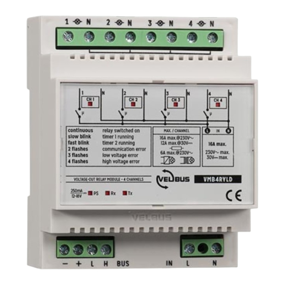
The VMB4RYLD is a 4-channel voltage-out relay module with common neutral poles, where only the live pole is switched on each channel. The live and... -
Page 16: Din Rail Dimmer Modules
DIN RAIL DIMMER MODULES Depending on the type of load, you will need a particular dimmer. To directly connect your mains voltage lighting circuits you can use the Velbus VMDBMI-R dimmer module, or a Velbus four-channel 0-10 V control VMB4DC together with dimmers that use 0-10V analogue signalling as input (e.g. -
Page 17: Din Rail Shutter Modules
DIN RAIL CONFIGURATION MODULE In order to configure your Velbus system you will need a Velbus PC interface. Through the interface modules you will be able to use the free configuration software Velbuslink to program and monitor the Velbus modules. -
Page 18: Din Rail Input Modules
LEDs in its body. EXAMPLE In a home where one wants to have just twenty automated lights, one would need one VMBSMPS power supply and five VMB4RYLD relay modules in the electrical cabinet. ©2015 Velbus... -
Page 19: Which Modules Can I Use In My Home Along My Bus Cable
VMB2PB(A)N with integrated LEDs (blue or amber) and a 6 button version VMB6PB(A)N are also available. Velbus glass touch panels Our VMBGPxxx glass touchpanels (VMBGPOD shown left, VMBGP1, VMBGP2 and VMBGP4, each in black or white) offer a fantastic choice of operating modes and functions. -
Page 20: Pc Interface Vmb1Usb
MOTION AND TWILIGHT SENSORS Velbus has its own motion, twilight and temperature sensors to be installed along the bus. The VMBPIROW (white) and VMBPIROB (black) -
Page 21: Heating / Cooling Control
VELBUS INSTALLATION GUIDE HEATING / COOLING CONTROL Velbus control of the heating/cooling system is possible in two ways (which can be complementary if needed): by using glass touch panels (VMBGPODB/W, VMBGP1B/W, VMBGP2B/W and VMBGP4B/W). These all have built-in temperature sensors and thermostat functions. -
Page 22: Connecting The Modules
5 CONNECTING THE MODULES TERMINATORS Each Velbus module has a terminator that is open on delivery. In a normal Velbus system two terminators should be closed, ideally at the extreme ends of the installation. Usually a terminator is closed somewhere in the first electrical cabinet and another one at the end of (more or less) the longest cable. - Page 23 VELBUS INSTALLATION GUIDE by the system. They are not to be used as addresses for active Velbus modules. Example: the hexadecimal address 1A is the same as the decimal address 11, they are only represented in a different way. The configuration software Velbuslink can be configured to display addresses decimally or hexadecimally, according to the user’s preference (menu “View”).
-
Page 24: Bus Wiring
At every joint the polarity of the power supply (+ and -) and data bus (H and L) must be maintained! If mistakes are made in this respect, nothing will be broken but your Velbus system will not work. Prevention is better than cure so due attention should be paid in order to avoid problems later on. - Page 25 To facilitate wiring in the electrical cabinet and allow for easy isolating of branches of the installation, Velbus also provides the VMBTB bus terminal. This distribution terminal block easily connects up to 8 bus cables of 4 wires. The spring contacts allow to connect or disconnect each cable separately.
-
Page 26: Other Wiring
(see “DIN rail dimmer modules” p.16), and so on. Once power is up on your Velbus system, you can already control each module (relay, dimmer, shutter, etc.) using the small button located behind each plastic cover, even before any programming has taken place. -
Page 27: Programming The Modules
"button pressed" pulse appears on the bus. This command is very simple for the Velbus network to react to as very few pieces of information need to be present on the data bus at any one time. - Page 28 Equally, opening and closing a Velbus relay channel also generates a pulse on the Velbus data bus and can in turn trigger other actions. It can have an effect on other output modules, or it can act as specific status reporting back to a particular input module.
-
Page 29: Getting Started With A New Project
GETTING STARTED WITH A NEW PROJECT Creating a new Velbuslink project We will assume from this step on that you are working with a live Velbus installation, connected to your PC with a USB cable. Make sure none of your Velbus modules are in error mode (LEDs blinking several times, pause, then blinking again). - Page 30 VELBUS INSTALLATION GUIDE Choose a filename and folder, and click “next”. Select “connect to my existing installation” and press “next”. ©2015 Velbus www.velbus.eu...
- Page 31 In the following window, select “Direct cable connection (RS232, USB)” and press “next”. The software will automatically choose the port on which the Velbus USB module is connected. Click “finish” to automatically establish a connection and start configuring your devices.
- Page 32 VELBUS INSTALLATION GUIDE Now select “scan my installation for modules”. This will make Velbuslink scan the bus for modules. Click “next” to proceed. A window will pop up, showing the progress of the scan. ©2015 Velbus www.velbus.eu...
- Page 33 A window may pop up showing the progress of the memory read, after which you will be notified that your new project has been created. Press “Finish” to start configuring your Velbus installation. ©2015 Velbus www.velbus.eu...
- Page 34 VELBUS INSTALLATION GUIDE Changing electronic addresses All Velbus modules need to have a unique address. (In this manual we will use hexadecimal representation. See “Addresses” p.22 for more). With a new installation, most modules will probably appear with exclamation marks next to them.
- Page 35 To change the addresses, we can use automatic detection. Note: Only use the “automatic detection” function if no two modules with the same address (apart from “FF”) are present in your Velbus system. If this should be the case, manually change the duplicates into new, unused addresses first.
- Page 36 VELBUS INSTALLATION GUIDE If you now physically press a button on a module, the module will be automatically selected in Velbuslink for you to change its address. (As soon as a module has been detected, the “Automatically select detected modules”...
- Page 37 When all modules have unique addresses, close the address management dialog and check the list of modules in your Velbus system to confirm that none have a red exclamation mark showing. Most recent modules have a blank space on their cover for you to write notes...
- Page 38 VELBUS INSTALLATION GUIDE Operating channels from within Velbuslink You can operate a channel from within Velbuslink by right-clicking on the channel (for instance a relay channel) and choosing“operate” from the drop down list that appears. A window will pop up allowing you to operate the channel, e.g.
- Page 39 VELBUS INSTALLATION GUIDE Renaming the modules and channels In a new Velbuslink project the module names will default to their type, but they can then be renamed (eg. VMBGPOD could become “GPOD-Master Panel”). Names can be 15 characters long. Most module names are stored only in Velbuslink and not in the modules.
- Page 40 VELBUS INSTALLATION GUIDE Optional: Layers If you have many modules, you may want to organise them in layers, which you can hide or show. You can for instance put all input modules on the ground floor in one layer, and all input modules on the first floor in another layer. You can then make these layers visible or invisible in the navigator window.
- Page 41 VELBUS INSTALLATION GUIDE Once the layers have been created, go back to the navigator window. Modules can now be assigned to a layer by selecting the module and clicking on the “Assign to a layer” icon . Adding, naming or deleting a layer has no effect on the project, apart from making certain modules temporarily visible or invisible in the navigator window.
- Page 42 Velbuslink, the channels will have appeared in the order you activated them and you can rename them accordingly. Recap In short, to get started with a new Velbus project, follow the next steps: connect your Velbus installation to your PC (for instance with a USB cable to a VMBRSUSB configuration module) ...
-
Page 43: Creating Actions
VELBUS INSTALLATION GUIDE CREATING ACTIONS Introduction In Velbuslink, all connections between various channels are created following the basic pattern “initiator” – “action” – “subject”. Action Initiator Subject For instance, to make a push button switch a light relay on and off, you would... - Page 44 VELBUS INSTALLATION GUIDE see the “L Kitchen” being dropped on top of VMB4RYNO’s relay channel no. 1 “Kitchen light”. Doing this will cause the “action properties” window to appear, and be pre- populated with the combination selected by this “drag and drop” process.
- Page 45 VELBUS INSTALLATION GUIDE Start by double clicking on either the input button or the output channel that you want to feature in the next action. Here we have double clicked the same “L Kitchen” button as above. As before, the “Action” window will appear, and the input selection will be pre- populated with the button selected here.
- Page 46 VELBUS INSTALLATION GUIDE Each module’s channels are only shown after the module has been expanded (by clicking on the “+” sign to the left of it). With the desired output channel highlighted, click on “OK”. The selection window will close and take you back, so that you can now choose the type of action you want to happen (see “1.
-
Page 47: Visualizing And Modifying Actions
VELBUS INSTALLATION GUIDE A window will pop up “Attempting to detect…”. Press the physical button you want to use, and its corresponding channel will be detected by Velbuslink. If the detection does not seem to work, make sure the appropriate filters are checked at the bottom of the “attempting to detect…”... - Page 48 VELBUS INSTALLATION GUIDE up. All properties of the action (initiator, subject, action type and parameters) can be changed. Changes will only be written to the modules after synchronisation (write) of course. Double-click to edit action NAVIGATOR PANE ACTIONS PANE In the navigator window, you can also see that next to every channel associated with an action, a “chain link”...
-
Page 49: Changing Feedback Characteristics Of Input Modules
VELBUS INSTALLATION GUIDE The icon key can be shown by pressing the “legend” button at the bottom of the main window. CHANGING FEEDBACK CHARACTERISTICS INPUT MODULES By default any feedback provided by an input module, be it a VMB8PBU, a VMBxPBN or a VMBGPxxx, will represent the state of the output connected to it. - Page 50 VELBUS INSTALLATION GUIDE LED to show the state of the light. You can use this feedback LED to show the state of the light in the children’s room, for instance. To do so, two steps need to be taken. Step 1 is to configure the button channel to change its default feedback behaviour to “Monitoring”:...
-
Page 51: Forcing And Inhibiting
VELBUS INSTALLATION GUIDE As always, don’t forget to synchronize (write) your project. The feedback LED of the push button in the living room will now reflect the state of the light in the children’s room. Other examples of possible LED feedback configurations are: showing the status of a doorbell, a light in an out building, or even the status of a connected burglar alarm (depending on hardware capability). - Page 52 VELBUS INSTALLATION GUIDE off (released) from 23.00 until 23.30. At 23.30, coming out of inhibition mode, it will execute the 5 remaining minutes of the “on during 15 minutes” command. Forcing A forced channel can be “forced on” or “forced off”. While forced, it will no longer respond to signals coming from the bus.
-
Page 53: Configuring Modules
CONFIGURING MODULES All addressable Velbus modules have settings that can be configured. These vary depending on the type of module. Relay channels for instance can be set to “normally closed” or “normally open”. For input buttons the array of... -
Page 54: Heating/Cooling Control
> Products. HEATING/COOLING CONTROL Velbus can easily be configured to command a heating and/or cooling system (see “Heating / cooling control” p.21 for a quick overview of relevant modules). We will explain here the principle of heating control using a VMBGPOD glass panel with OLED display as master panel in the living room, and a VMBGP2 two- button glass panel in the bathroom. - Page 55 VELBUS INSTALLATION GUIDE Check the “Use thermostat” checkbox. The input field for the thermostat will become active. Fill in a free address between 01 and FE and press Enter or click on the “Change” button. Do the same for other modules as necessary. Press “Close”...
- Page 56 VELBUS INSTALLATION GUIDE 3. Link sensors Next, we will link the VMBGP2 “Bathroom” temperature sensor to the VMBGPOD master panel, so the first can be accessed from the latter’s display. In the VMBGPOD configuration settings, go to the tab Temperature > Remote, select the “Bathroom”...
- Page 57 Finally, we need to create the right connections (actions) between the temperature sensors and the relay channels controlling the heating system. How the Velbus relays need to be physically connected to the heating system depends on the specific system. A standard setup could be, for instance, one relay commanding the central pump of the heating system, and for each heating circuit a separate relay channel that controls the flow valve.
- Page 58 In the example below, the measured temperature is 22,5°C. As the target temperature is set at 25°C, the heater and pump channels are closed (“Pressed”). Schematically represented, the actions to be created are the following (see “Creating actions” p.43 for more information on Velbus actions): ©2015 Velbus www.velbus.eu...
-
Page 59: Creating And Modifying Program Steps
CREATING AND MODIFYING PROGRAM STEPS Program steps for input modules All Velbus input modules can be programmed to activate, deactivate, lock, unlock, press, long press or release their own channels at certain times. Time settings can be fixed times, sunrise/sunset with or without offset, and more. - Page 60 VELBUS INSTALLATION GUIDE Program steps are configured on the “Program steps” tab of the configuration dialog (see “Configuring modules” above for instructions on how to access the configuration dialog). Click on the “Add” button to create a new program step.
- Page 61 The programs in an input module can also be manipulated by certain actions coming from other Velbus modules. To do so, create an action and as subject choose the input module, channel “Module programs”. ©2015 Velbus...
- Page 62 VELBUS INSTALLATION GUIDE Available actions are selecting/deselecting programs, enabling disabling alarms, and so on. Alternatively, programs can also be enabled and disabled for a specific input channel instead of the whole input module. To do so, create an action with the input channel as the subject.
-
Page 63: Help! What Have I Done Wrong
Device Manager). Start this program and scroll down to “Ports (COM & LPT)”. Display the contents of the “Ports (COM & LPT)” category by clicking on the small triangle to the left. Right click on “VMB1USB Velbus USB Interface” and select “Update driver”. - Page 64 The scan worked perfectly but now, using the same port, I can’t find my installation anymore The hardware of your USB port may lose communication with your Velbus system, for instance after your PC enters sleep mode. The simplest solution is to plug the USB cable into another port, forcing the system to re-initialise.
- Page 65 VELBUS INSTALLATION GUIDE Double check the addresses of the "missing" modules. There is a chance that addresses have been duplicated. Do not forget that addresses of the VMB4PD and VMB1TC can be manually set via the module. ...
- Page 66 VELBUS INSTALLATION GUIDE All modules with electronic addressing can use the full HEX range of 01-FE (in decimal notation: 01 – 254). In any case, check also if there are no wiring problems and restart the system if necessary (power down, wait a few seconds and power up again).
- Page 67 Only synchronise when there are no red ‘X’ marks or exclamation signs next to any of your listed modules. For best results, only work on a software configuration once the Velbus system has been scanned by Velbuslink to confirm the presence of all of your modules.
-
Page 68: Frequently Asked Questions
Can I run multiple simultaneous operations (such as push ten buttons simultaneously)? In a Velbus system there is only communication on the data bus when a button is pressed or released. For example, during the process of dimming a light fixture, the data bus is empty. - Page 69 VELBUS INSTALLATION GUIDE To begin with, most modules have a large range of built-in actions, including: inhibiting and forcing actions with two levels of priority, multiple types of timers and time-dependent programming of channels. Free (real or virtual) channels of relay modules can also be used as virtual switches, allowing conditional actions to be configured, and many different actions and programs can be used together in the same module.
- Page 70 VELBUS INSTALLATION GUIDE The master clock will send its time and date to the other modules once a day. This way, all modules remain perfectly synchronized. Only set one master clock per installation. 3. Manually setting the time and date To manually (re)set the time and date, two options are available.
Need help?
Do you have a question about the VMB4RYLD and is the answer not in the manual?
Questions and answers