
Related Manuals for Garudan GPS/X-3525 Series


Summary of Contents for Garudan GPS/X-3525 Series
- Page 1 User´s Manual GPS/X-3525 ANITA B s.r.o. Průmyslová 2453/7 680 01 Boskovice Czech Republic tel: +420 516 454 774 +420 516 453 496 fax: +420 516 452 751 e-mail: info@anita.cz MP03200EN_180810...
- Page 2 © ANITA VERSION CREATED ON APPROVED BY MP03200EN_180810 10. 08. 2018 Jakub Lžičař All rights reserved. Property of Anita B s.r.o. and protected by copyright. The use of this content without written permission is prohibited. Copyright © Anita B s r.o. (2018) MP03200EN_180810...
-
Page 3: Table Of Contents
© ANITA Content 1. Specification ........................... 4 2. Description ..........................5 3. Safety instructions ........................6 4 Safe installation ........................9 5 Electric device setting ......................9 6 Disposal instructions ....................... 9 7 Before machine operation ....................10 Lubrication: ......................10 Needle insertion: .................... -
Page 4: Specification
© ANITA 1. SPECIFICATION GPS/X-3525G extra heavy material GPS/X-3525_ _-xx/xx/xx feeding frame type (2 – piece = 22; for Model template loading = 24); Options, e.g., barcode reader BR, Control of the machine through buttons HC, needle cooler NC, safety curtain SC, mouse port MP Sewing area 350 x 250 mm... -
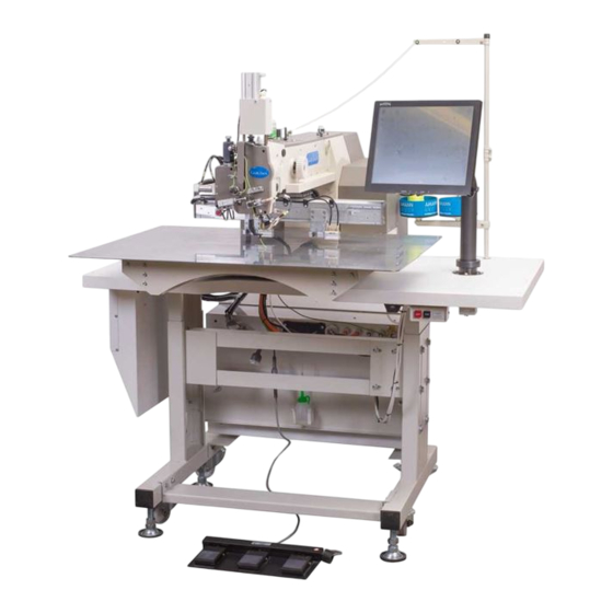
Page 5: Description
© ANITA 2. DESCRIPTION Fig. 1 MP03200EN_180810... -
Page 6: Safety Instructions
© ANITA 3. SAFETY INSTRUCTIONS Based on the TUV SUD Conformity Compliance and compliance with all standards, each machine is CE marked - Declaration of Conformity. General Safety Instructions Read this manual, operating instructions and operating instructions thoroughly before using the machine. - Page 7 © ANITA Safety instructions for installation and maintenance The machine should be installed and run for the first time only by a trained person. Interference with electrical circuits may only be carried out by a trained person with Order No. 50/158 sb.6 and higher. Ensure that the power supply, voltage, sizing, and fuse is such as to allow the constant supply of the energy required for reliable machine performance.
- Page 8 © ANITA E Security sticker on the control box. Danger of dangerous voltage. F Sewing area. Protected by a hinged transparent cover. Puncture or puncture - hand injury. H Hook space. Protected by a hinged cover. Cutting - Hand Injury. I Moving mechanism space - X and Y axis movements.
-
Page 9: Safe Installation
© ANITA 4 SAFE INSTALLATION All installation and service work have to be done without power supply. A. The machine cannot be used if voltage is 10% above or 10% below the formal voltage. B. Check if there is correct air pressure in the pneumatic system. C. -
Page 10: Before Machine Operation
© ANITA 7 BEFORE MACHINE OPERATION 1. Lubrication: Check the amount oil in the oil gauge Windows. Fill up the oil Fig. 3, 4 Fig. 4 Fig. 3 Machine should be lubricated before its first use or if reused after a long period of idleness or according to traffic in regular intervals, at least at the beginning of each shift. -
Page 11: Needle Insertion
© ANITA 2. Needle insertion: Loosen the screw of needle holder (1), fully insert the needle (2) into the needle socket in needle holder while keeping the needle slot (3) facing tip of the hook, then tighten it with the screw (1), see Fig. 7. Fig. -
Page 12: Bobbin Threading
© ANITA 4. Bobbin threading: A. Put bobbin (1) into bobbin case (2) as the Fig. 9 shows (the shuttle rotates in clockwise direction). B. Bobbin thread is led through the bobbin case spring and bobbin case hole (3) C. The remain of bobbin thread end should be kept about 55mm long. -
Page 13: Thread Tension Adjustment
© ANITA 6. Thread tension adjustment: A. Needle thread tension adjustment, Fig. 11: As the Figure shows turn screw (1) of the main tensioner clockwise to increase the tension, while counter clockwise to reduce the tension. Additional tensioner (2) is used for final adjustment of the end of needle thread after trimming. -
Page 14: Adjusting Height Of Presser Foot
© ANITA 8. Adjusting height of presser foot: Adjustment of the foot is described in Chapter 4, page 17. The presser foot is mounted on the presser bar to the end of casting. If you need to adjust the through hole on the needle axis, loosen the presser foot 1 by loosening the screws. -
Page 15: Mechanical Maintenance
© ANITA 8 MECHANICAL MAINTENANCE 1. Running settings of the driver and needle bar: Notice: The driver of the needle bar 1, Fig. 16 is mounted on the presser bar to the end of casting 2, Fig. 16 (there are two different diameters of the needle bar). Adjust the needle bar by turning the hand wheel into the bottom position, Fig. -
Page 16: Needle To Hook Relationship
© ANITA Needle to hook relationship For adjustment, loosen the bolt 3 on the lever 2 with a clamping connection on the lower shaft 1, Fig 17. Place the needle bar at the bottom position. (the rod is in alignment with the needle bar). Turning the hand wheel in the sewing direction shifts the needle bar 4.5 to 5mm upwards. -
Page 17: Adjustment Of Presser Foot
© ANITA 4. Adjustment of presser foot: a) Set the needle bar to the Loir reversal point by turning hand wheel. Loosen screws (2) of the eccentric (1) as per Fig.20 and set this eccentric to the position where the presser bar (9) starts moving together with the needle bar or with a little delay (see Fig. -
Page 18: Thread Of Upper Thread
© ANITA Lever 4, (Fig. 22), is driven by the eccentric and it is joined with the adjusting pin and nut on the lever with the groove (5) in the part located outside the machine. If the pin is in the upper part of the groove, the presser foot movement is set to minimum. -
Page 19: Opening Of The Main Tensioner Discs
© ANITA Fig. 24 Fig. 25 6. Opening of the main tensioner discs: Release of the main tensioner discs (5) is performed by pneumatic cylinder connected with the rod (Fig.24). Setting of the cylinder is made by parameter 16. This parameter defines position of the needle at the moment, when the tensioner discs are opened. -
Page 20: Adjustment Of Trimming Mechanism
© ANITA 7. Adjustment of trimming mechanism: Adjustment of fixed and moving knife, Fig. 26. a) Move with needle bar to the upper position. b) Set the position of fixed knife (1) so that its sharp edge is in distance of 8 mm from the center of the needle plate insert (2). -
Page 21: Adjustment Of Speed Of Movement Of The Trimming Lever
© ANITA 8. Adjustment of speed of movement of the trimming lever: Correct function of pneumatic cylinder of trimming is done by air pressure in value 0.55 - 0.6 MPa. Regular length of bottom thread after trimming is 55mm. The trimming is controlled by below parameters: Parameter 21 Decelerate stitches –... -
Page 22: Setting Of Hand Wheel
© ANITA 9. Setting of hand wheel: a) Press the hand wheel (1) in the direction of the arrow and turn the wheel until the roller leans against longer side of the bushing (3). See Fig. 29. b) Set the correct clearance on conical gearwheels of the main shaft (4) and hand wheel shaft (5). -
Page 23: Sensors For Initial Position Of X, Y And Z Axis
© ANITA 11. Sensors for initial position of X, Y and Z axis: Default setting for initial position of X and Y axis initial point and position of Z axis (needle) is set in the production plant. a) Sensors are placed on the machine arm, under left cover of the linear railway (Fig. 32). b) X axis movement position can be set by moving sensor plate (2) against the sensor (1). -
Page 24: Barcode Reader
© ANITA Fig. 33 12. Barcode reader: Fig. 32 shows position of the barcode reader (5) on the machine. 13. Feeding frame: Machine can be supplied either with the system of 2-piece upper presser frame (1, 2) and 1-piece lower feeding frame (3) – see Fig. 34, or it is supplied with customized clamp/pallet according to individual order of the customer –... -
Page 25: Thread Holder
© ANITA Fig. 34 14. Thread holder: Fig. 34 shows position of the thread holder (6). This device is activated by parameter 32. Default value is 80 15. Needle cooling: Fig. 34 shows position of nozzle (7) used for needle cooling. This function is activated by parameter Fig. -
Page 26: Lubrication Of Ball Screw Shaft Bering
© ANITA 17. Lubrication of ball screw shaft Bering: Lubrication of ball screw shaft bearing ensures movement of the frame in axes X and Y Unscrew the screws of the back cover (1) (two screws from back side and 3 screws on each side) and remove the cover (Fig.36). -
Page 27: Connection To Air Supply
© ANITA 18. Connection to air supply: a) Connect air hose to nipple (1) on the entry unit /2), see Fig. 38. b) Open air valve (3). c) By turning the knob (4) on the entry unit set the pressure for the value 0,55 - 0,6 MPa. Check the correct air pressure value on the manometer gauge. -
Page 28: Operation Of Pedals
© ANITA 19. Operation of pedals: a) Function of pedals can be defined according to requirement of operator by parameters 8,9 and 10. b) Machine is standardly supplied with 2-piece presser frame and 3 pedals (see chart 1). If middle pedal is not used, it is possible to use the same setting which is used for machine with 2 pedals (see chart 2). -
Page 29: Chart Of Maximum Sewing Speed
© ANITA 20. Chart of maximum sewing speed: The chart defines maximum sewing speeds with relation to different stitch lengths. Sewing speed can be lower than the maximum speed but should not exceed the maximum speed defined for the respective stitch length. Straight stitch ZigZag stitch Stitch length (mm) -
Page 30: Troubleshooting
© ANITA 9 TROUBLESHOOTING No. Type of the problem Cause of the problem Solution Error message on the display of Inform manufacturer about needle motor driver for X or Y the type of error message axis Check fuses in the Fuse is short-cut switchboard Error of control... - Page 31 © ANITA Wrong threading of upper Make correct threading thread Wrong position of needle Set correct position of needle Damaged needle Exchange needle Wrong tension of upper or lower Re-install correct thread thread tension Broken thread Re-install correct tension and Wrong tension and rigidity of rigidity of thread tension thread tension spring...
- Page 33 Spare Parts List GPS/X-3525 ANITA B s.r.o. Průmyslová 2453/7 680 01 Boskovice Czech Republic tel: +420 516 454 774 +420 516 453 496 fax: +420 516 452 751 e-mail: info@anita.cz MP03200EN_180822...
- Page 34 © ANITA VERSION CREATED ON APPROVED BY MP03200EN_180822 22. 08. 2018 Jakub Lžičař All rights reserved. Property of Anita B s.r.o. and protected by copyright. The use of this content without written consent of Anita B s.r.o. is prohibited. Copyright © Anita B s.r.o. (2018) MP03200EN_180822...
- Page 35 © ANITA Obsah A. Frame and Machine Body Parts ..................... 4 B. Upper Shaft and Main Shaft Mechanism (1/2) ..............6 B. Upper Shaft and Main Shaft Mechanism (2/2) ..............8 C. Presser Foot Mechanism (1/2) ..................... 10 C. Presser Foot Mechanism (2/2) ..................... 12 D.
-
Page 36: Frame And Machine Body Parts
© ANITA A. FRAME AND MACHINE BODY PARTS MP03200EN_180822... - Page 37 © ANITA A. FRAME AND MACHINE BODY PARTS Ref.No Parts No. Name of parts Description Note A0123525_X AnB-3525-826 Plate A0223525_X Bedplate AnB-3525-895 Top Cover AnB-3525-853 Face Cover AnB-3525-880 Back Cover AnB-3525-881 Distance Bracket AnB-3525-064 Distance Bracket M10 DIN 934 M6x10 DIN 912 Screw 6 DIN 152A Washer...
-
Page 38: Upper Shaft And Main Shaft Mechanism (1/2)
© ANITA B. UPPER SHAFT AND MAIN SHAFT MECHANISM (1/2) MP03200EN_180822... - Page 39 © ANITA B. UPPER SHAFT AND MAIN SHAFT MECHANISM (1/2) Ref.No Parts No. Name of parts Description Note AnB-3525-909 Upper Shaft with Cam Assy´y 4710190100 Thread Take-up Lever 4710190300 Roller Pin 4710190200 Roller 5 DIN 6799 Retaining Washer AnB-3525-829 AnB-3525-848 Pin Holder M6x10 DIN 913 Screw...
-
Page 40: Upper Shaft And Main Shaft Mechanism (2/2)
© ANITA © ANITA B. UPPER SHAFT AND MAIN UPPER SHAFT AND MAIN SHAFT MECHANISM (2/2) MP03200EN_180822... - Page 41 © ANITA B. UPPER SHAFT AND MAIN SHAFT MECHANISM (2/2) Ref.No Parts No. Name of parts Description Note M4x10 DIN 84 Screw 4 DIN 127A Spring washer B3006032 Z-sensor bracket K4001507 Sensor M4x12 DIN 912 Screw M6x6 DIN 913 Screw M5x6 DIN 913 Screw MP03200EN_180822...
-
Page 42: Presser Foot Mechanism (1/2)
© ANITA C. PRESSER FOOT MECHANISM (1/2) MP03200EN_180822... - Page 43 © ANITA C. PRESSER FOOT MECHANISM (1/2) Ref.No Parts No. Name of parts Description Note AnB-3525-832 Bracket AnB-3525-910 Excentr 4710144500 Lever ZSG22002 Connection Pin WH208005 Distance Ring 4710144700 Take-up Lever M6x20 DIN 912 Screw M6x6 DIN 913 Screw 6-20m6 DIN 6325 AnB-3525-807 Feeding Shaft 4710144700...
-
Page 44: Presser Foot Mechanism (2/2)
© ANITA C. PRESSER FOOT MECHANISM (2/2) MP03200EN_180822... - Page 45 © ANITA C. PRESSER FOOT MECHANISM (2/2) Ref.No Parts No. Name of parts Description Note AnB-3525-829 Finger guide M4x8 DIN 967 Screw M6x6 DIN 913 Screw AnB-3525-883 Link AnB-3525-884 Connecting rod AnB-3525-918 4 DIN 6799 Washer AnB-3525-886 Plate AnB-3525-885 Strut M5 DIN 934 AnB-3525-887 Cover...
-
Page 46: Lower Shaft And Shuttle Mechanism (1/2)
© ANITA D. LOWER SHAFT AND SHUTTLE MECHANISM (1/2) MP03200EN_180822... - Page 47 © ANITA D. LOWER SHAFT AND SHUTTLE MECHANISM (1/2) Ref.No Parts No. Name of parts Description Note AnB-3525-842 Lower Shaft Ass´y AnB-3525-872 Connecting Rod Ass´y 4710182100 Bearing AnB-3525-911 Excentric Cam 4710182000 Cam Side Plate 4710183400 ZMJ06006 Screw WA06008 Washer B4406032 Collar M5x6 DIN 913 Screw...
-
Page 48: Lower Shaft And Shuttle Mechanism (2/2)
© ANITA D. LOWER SHAFT AND SHUTTLE MECHANISM (2/2) MP03200EN_180822... - Page 49 © ANITA D. LOWER SHAFT AND SHUTTLE MECHANISM (2/2) Ref.No Parts No. Name of parts Description Note AnB-3525-912 Screw 4710183800 Spring MP03200EN_180822...
-
Page 50: Thread Trimming Mechanism (1/2)
© ANITA E. THREAD TRIMMING MECHANISM (1/2) MP03200EN_180822... - Page 51 © ANITA E. THREAD TRIMMING MECHANISM (1/2) Ref.No Parts No. Name of parts Description Note AnB-3525-819 Needle Plate E3606032 Screw Needle Plate Cover – hole 3.5 AnB-3525-828 Needle Plate Cover – hole 4.5 AnB-3525-841 M3x4 DIN 963 Screw AnB-3525-905 Base Ass´y M5x12 DIN 912 Screw E9056032...
-
Page 52: Thread Trimming Mechanism (2/2)
© ANITA © ANITA E. THREAD TRIMMING MECH THREAD TRIMMING MECH ANISM (2/2) MP03200EN_180822... - Page 53 © ANITA E. THREAD TRIMMING MECHANISM (2/2) Ref.No Parts No. Name of parts Description Note M5x12 DIN 912 Screw M5x45 DIN 912 Screw 5 DIN 125A Washer M6x14 DIN 912 Screw 6 DIN 125A Washer MP03200EN_180822...
-
Page 54: X-Moving Mechanism (1/2)
© ANITA G. X-MOVING MECHANISM (1/2) MP03200EN_180822... - Page 55 © ANITA G. X-MOVING MECHANISM (1/2) Ref.No Parts No. Name of parts Description Note G2506032 T. belt G7203020 Ball Screw Shaft G7503525 Bushing G7603020 Driven Pulley G3506032 Driven Gear G7803525 Bushing G8023525 Axis Rack G8803020 Washer MB3 G8703020 Nut KM3 AnB-3525-844 X Axis Moving Frame G8103020...
-
Page 56: X-Moving Mechanism (2/2)
© ANITA G. X-MOVING MECHANISM (2/2) MP03200EN_180822... - Page 57 © ANITA G. X-MOVING MECHANISM (2/2) Ref.No Parts No. Name of parts Description Note DIN 912 M5x16 Screw DIN 912 M4x14 Screw DIN 912 M4x12 Screw DIN 912 M6x25 Screw DIN 912 M5x25 Screw DIN 912 M10x90 Screw DIN 912 M10x40 Screw DIN 912 M8x25 Screw...
-
Page 58: Feed Frame Mechanism (1/2)
© ANITA I. FEED FRAME MECHANISM (1/2) MP03200EN_180822... - Page 59 © ANITA I. FEED FRAME MECHANISM (1/2) Ref.No Parts No. Name of parts Description Note S4483525 Plate S4513525 Plate Holder I2906032 Plate Holder S4183525 Feed plate lower Upper feed plate bracket S4063525 segment Upper feed plate flexible S4533525 mounting DIN 965/Z M6x8 Screw S4033525 Holder...
-
Page 60: Feed Frame Mechanism (2/2)
© ANITA I. FEED FRAME MECHANISM (2/2) MP03200EN_180822... - Page 61 © ANITA I. FEED FRAME MECHANISM (2/2) Ref.No Parts No. Name of parts Description Note 5 DIN 125A Washer AnB-3525-927 Screw pin MP03200EN_180822...
-
Page 62: I2. Feed Frame For Customer Design
© ANITA I2. FEED FRAME FOR CUSTOMER DESIGN MP03200EN_180822... - Page 63 © ANITA I2. FEED FRAME FOR CUSTOMER DESIGN PATTERN Ref.No Parts No. Name of parts Description Note I3006032 Block stopper I2806032 Bracket AnB-3525-867 Holder CQ2B12-20DM Pneumatic cylinder KQ2H04-M5 Hose nipple I3106032 Knuckle pin M4x12 DIN 912 Screw M3x35 DIN 912 Screw M6x8 DIN 965A Screw...
-
Page 64: Thread Tension Mechanism
© ANITA J. THREAD TENSION MECHANISM MP03200EN_180822... - Page 65 © ANITA J. THREAD TESION MECHANISM Ref.No Parts No. Name of parts Description Note AnB-3525-863 Thread Tension Adjusting Ass´y 1 set AnB-3525-852 Bushing AnB-3525-879 M3x16 DIN 912 Screw C85RAF20-10 KQ2L04-01AS Hose nipple M5x30 DIN 912 Screw Second Thread Tension AnB-3525-856 Adjusting Ass´y 5 DIN 125A Washer...
-
Page 66: Bobbin Winder And Hand Pulley
© ANITA K. BOBBIN WINDER AND HAND PULLEY MP03200EN_180822... - Page 67 © ANITA K. BOBBIN WINDER AND HAND PULLEY Ref.No Parts No. Name of parts Description Note AnB-3525-908 Gear AnB-3525-907 Gear AnB-3525-904 Hand Wheel Pin AnB-3525-889 Hand Wheel 341901 Screw M5x6 DIN 913 Screw D0301507 Spring AnB-3525-905 Bushing AnB-3525-906 4710320500 Friction Wheel 4710320805 Bobbin Winder AnB-3525-870...
-
Page 68: Stand And Table
© ANITA L. STAND AND TABLE MP03200EN_180822... - Page 69 © ANITA L. STAND AND TABLE Ref.No Parts No. Name of parts Description Note Plát CZ B07 Table AnB-3525-029 Frame AnB-3525-032 Left Holder AnB-3525-869 Holder AnB-3525-877 Table Stainless Steel AnB-3525-897 Front Sheet AnB-3525-876 Holder AnB-3525-061 Right Holder JAM-10 Stand FJGN20-100 Adjustable Foot Roz3525 Control Box...
-
Page 70: Lubrication Parts
© ANITA M. LUBRICATION PARTS MP03200EN_180822... - Page 71 © ANITA M. LUBRICATION PARTS Ref.No Parts No. Name of parts Description Note M0106032 Cover M0206032 Cover Gasket M0306032 Oil Tank Gauge HEYMAN 3376 Holder 9,5 M4x8 DIN 912 Screw A4,3 DIN 125 Washer A4 DIN 127 Spring Washer M0806032 Holder of Oil Cap M0906032 Oil Pan...
-
Page 72: Air Control Parts
© ANITA N. AIR CONTROL PARTS MP03200EN_180822... - Page 73 © ANITA N. AIR CONTROL PARTS Ref.No Parts No. Name of parts Description Note AR10-M5H Regulator of pressure G27-10-R1 Manometer AR10P-270AS Holder KQ2L04-M5 Hose nipple U0301507 Filter Regulator U0201507 Finger Valve U0401507 Clutch U0831507 Plate Standard TV25110-06 Magnetic Valve Standard U1001507 Plug U0901507...
-
Page 74: Operation Unit And Thread Stand
© ANITA Q. OPERATION UNIT AND THREAD STAND MP03200EN_180822... - Page 75 © ANITA Q. OPERATION UNIT AND THREAD STAND Ref.No Parts No. Name of parts Description Note O2201507 Holder LCD O2101507 Touch LCD 15” M8x20 DIN 912 Screw M8x50 DIN 912 Screw A8,4 DIN 125 Washer A8 DIN 127 Spring Washer M8 DIN 934 M6x14 DIN 912 Screw...
-
Page 76: Control Box
© ANITA R. CONTROL BOX MP03200EN_180822... - Page 77 © ANITA R. CONTROL BOX Ref.No Parts No. Name of parts Description Note R2053525 Converter R2056032 Converter R4201507 Board B C6461510 Drive for Motor of Axis Z R3201507 Power Supply ATX R3081507 PC module G LRS-150-24 Switch-mode Power Supply R1001507 Master Switch R1101507 Circuit Breaker...
- Page 78 © ANITA S. OPTION MP03200EN_180822...
- Page 79 © ANITA S. OPTION Ref.No Parts No. Name of parts Description Note S1816032 Holder of cooling needle M5x12 DIN 912 Screw 5 DIN 127A Spring washer 5,3 DIN 125A Washer M5X8 DIN 912 Screw KN-Q06-100 KQ2H04-06 Hose nipple NC0106032 Ring S1806032 Holder of cooling needle AS2001F-04...
Need help?
Do you have a question about the GPS/X-3525 Series and is the answer not in the manual?
Questions and answers