Table of Contents
Advertisement
Quick Links
Contexts ................................................................ .............Chapter - Page
1
Safety .............................................................................................................1 - 1
1
.01
Directives.........................................................................................................1 - 1
1
.02
General notes on safety...................................................................................1 - 1
1
.03
Safety symbols................................................................................................. 1 - 2
2
Proper use ...................................................................................................... 2 - 1
3
Specifications ................................................................................................ 3 - 1
3
.01
GP-710-148, GP-724-108.................................................................................. 3 - 1
3
.02
Needles and threads ...................................................................................... 3 - 2
3
.03
Possible models and subclasses ..................................................................... 3 - 2
4
Explanation of symbols ................................................................................ 4 - 1
5
Controls ........................................................................................................... 5 - 1
5.
01
Keys on machine head (only for machines with -D3/.. ) ................................... 5 - 1
5.
02
Bobbin thread monitoring with stitch counting ................................................. 5 - 2
5.
03
Pedal ................................................................................................................. 5 - 2
5.
04
Lever for lifting roller presser ........................................................................... 5 - 3
5.
05
Knee lever .......................................................................................................... 5 - 3
5.
06
Dey for seeting stitch length ........................................................................... 5 - 4
5.
07
Swing out roller presser ..................................................................................... 5 - 4
6
Installation and commissioning ................................................................. 6 - 1
6
.01
Installation......................................................................................................... 6 - 1
6
.01.01
Adjusting the table height................................................................................. 6 - 1
6
.02
Fitting the reel stand ........................................................................................ 6 - 2
6
.03
Tilted work base ............................................................................................... 6 - 3
6.
04
Table top cutout ............................................................................................. 6 - 4
6
.05
Mounting the table top..................................................................................... 6 - 5
7
Preparation........................................................................................................ 7 - 1
7
.01
Inserting the needle on model GP-710............................................................... 7 - 1
7
.02
Inserting the needle on model GP-724............................................................. 7 - 2
7
.03
Winding the bobbin thread; adjusting the bobbin thread tension ....................... 7 - 3
7
.04
Removing/Inserting the bobbin case .............................................................. 7 - 4
7
.05
Threading the bobbin case/Adjusting the bobbin thread tension ..................... 7 - 4
7
.06
7
.07
7
.08
Setting the stitch length .................................................................................... 7 - 7
8
Care and maintenance ................................................................................ 8 - 1
Checking/adjusting the air pressure....................................................................8 - 1
8.
02
Cleaning the air filter of the air-filter/lubricator............... ....................................8 - 2
Cleaning ........................................................................................................... 8 - 3
8.
04
Oiling the hook ................................................................................................. 8 - 4
8.
05
Oil bowl for hook lubrication....................................................................... 8 - 4
8.
06
Filling the oil reservoir of the thread lubrication unit ........................................ 8 - 5
8.
07
Lubricating the bevel gears ............................................................................. 8 - 6
9
Adjustment ...................................................................................................... 9 - 1
9.
01
Notes on adjustment........................................................................................... 9 - 1
Index
8.
01
8.
03
Advertisement
Table of Contents

Related Manuals for Garudan GP-724-108


Summary of Contents for Garudan GP-724-108
-
Page 1: Table Of Contents
Safety symbols.................……….…… 1 - 2 Proper use ……................……..…..2 - 1 Specifications ………..............……... 3 - 1 GP-710-148, GP-724-108........…........…. 3 - 1 Needles and threads …………...........…...…..…. 3 - 2 Possible models and subclasses ………..........…..….. 3 - 2 Explanation of symbols ……………...…............4 - 1 Controls ……….................... - Page 2 tools, gauges and other accessories..………………………………………..9 - 1 Adjusting the basic machine..………………..........9 - 2 03.01 Needle position in sewing direction on the GP-710………………..……....9 - 2 03.02 Needle position in sewing direction on the GP-724…………...…....9 - 3 03.03 Preliminary adjustment of the needle height……………………......9 - 4 03.04 Needle rise, hook clearance, needle height and needle grard on the H962 ..…………………………………………………………….……………….……..9 - 7...
-
Page 3: Safety
Safety 1.01 Safety symbols Danger! Points to be observed Danger of injury for operating and specialist personnel! Caution Do not operate without finger guard and safety devices. before threading,changing bobbin and needle, cleaning etc. switch off main switch. 工作中的特殊 1.02 Important points for the user ●... - Page 4 Safety —————————— Danger 1.03 A working area of 1 meter is to be kept free both in front of and behind the machine in operation so that the machine is always easily accessible. Never reach into the sewing area while sewing! Danger of injury by the needle! Never leave objects on the table while adjusting the machine settings! Objects can become trapped or be slung away! Danger of injury! Do not operate the machine without support1! Danger due to top-heavy sewing head!
- Page 5 Safety —————————— Switch the machine off before tilting it backwards! Danger of injury if the machine is started accidently! Do not operate the machine wihout its take-up-lever guard 2! Danger of injury due to the motion of the take-up lever! On machines with thread lubricator, only operate the machine with the eye guard 3 lowered! The eye guard 3 protects the eyes from oil particles from the thread lubrication! Do not operate the machine without belt guard 4!
-
Page 6: Proper Use
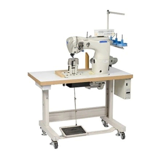
2 Proper use GP-724-108 s a double-needle, high-speed post bed sewing machine with driven feed wheel and roller presser. GP-710-148 Is a single needle, high-speed post bed sewing machine (post to the right of the needle) with driven feed wheel and roller presser and synchronized needle. -
Page 7: Specifications
3 Specifications 3.01 GP-710, GP724 Stitch type........…...…..…..301 (lockstitch) Clearacne under roller presser..…………..... 7 mm Clearance width ............... 245 mm Clearance height.....…............115 mm Post height ............... 180 mm Sewing head dimensions Length......…..........approx. 615 mm Width ..............…..approx. 240 mm Height (above table).......….. -
Page 8: Needles And Threads
3.02 Needles and threads (Nm) GP-710 GP-724 1/100mm 40/3 134-35 Thread ▲ thickness Needle Model (Nm) max. thickness GP-710 GP-724 Synthetics 1/100mm Needle system Needle system 40/3 134-35 ▲ or similar strengths of other types of thread 3.03 Possible models and subclasses Additional equipment Subclass-D………………….…………………………………..Automatic edge trimmer Subclass-D3…….Automatic edge trimmer, automatic presser foot lifter, backtacker. -
Page 9: Explanation Of Symbols
4 Explanation of symbols In this instruction manual, work to be carried out or important information is accentuated by symbols which have the following meanings: Note, information Cleaning, care Lubrication Maintenance, repairs, adjustment, servise work (only to be carried out by technical staff) -
Page 10: Controls
5 Controls 5.01 Keys on the machine head (only for machines with-D3) ● As long as key 1 is pressed during sewing, the machine sews in reverse direction. ● Keys 2 can be used for parameter settings, Instruction manual of electronic control. 5.02 Bobbin thread monitoring with stitch counting Machines without –D3/.. -
Page 11: Lever For Lifting Roller Presser
5.04 Lever for lifting roller presser ● The roller presser can be raised by turning lever1. 5.05 Knee lever ● The roller presser can be raised by pressing the knee lever 1 in the direction of the arrow. 5.06 Key for setting stitch length ●... -
Page 12: Swing Out Roller Presser
5.07 Swing out roller presser ● When the roller presser is raised, it can be swung out by pulling it lightly downwards. -
Page 13: Installation And Commissioning
6 Installation and commissioning The machine must only be installed and commissioned by qualified personnel! All relevant safety regulations must be strictly adhered to! If the machine is delivered without a table, be sure to use a stand and table top that can hold the weight of the machine with its motor. -
Page 14: Fitting The Reel Stand
6.02.01 Fitting the reel stand Fit the reel stand as shown in Fig. ● Afterwards insert the stand in the hole of the table top and secure it with the nuts provided. 6.02.02 Fitting the tilt lock 6.02.03 Fitting the machine cover... - Page 15 6.02.04 Mounting the flange motor to the bearing plate 6.02.05 Mounting the flange motor to the machine...
- Page 16 6.02.06 ● In this position fit toofhed belt 1. ● Swing the bearing plate 2 of the motor,so that the toothed belt is tensioned. ● In this position tighten screws 3. 6.02.07 Mounting the belt guard of the flange motor...
- Page 17 6.02.08 Connecting the safety switch ●Connect plug 1 of safety switch 2 as shown in Fig. When the sewing head is tilted back,the safety switch prevents the machine starting when the main switch is on. 6.01 Commissioning 6.02 ● Check the machine, particularly the electrical wriring for any damage. ●...
-
Page 18: Tilted Work Base
6 Installation and commisioning 6.04 Tilted work base 6.05 Tilted work base... -
Page 19: Mounting The Table Top
6.06 Mounting the table top... -
Page 20: Preparation
Preparation —————————— Setting up All instructions and regulations in this instrution manual must be observed . Special attention must be paid to all safety regulations! All setting-up work must only be carried out by personnel with the appropriate training. For all setting-up work the machine must be disconnected from its power supply by turning off the on/off switch, or removing the plug from the electric power socket. -
Page 21: Inserting The Needle On Model Gp-710
7 Preparation 7.02 Inserting the needle on model GP-724-108 Switch the machine off! Danger of injury if the machine is started accidentally! Only use needles of system 134-35. ● Raise the roller presser 1 and swing it out. ● Loosen screws 2 and insert the needles so that the long groove of the left needle is facing right, and that of the right needle is facing left. -
Page 22: Removing/Inserting The Bobbin Case
● Turn thread guide 6 accordingly Tighten nut 5. 7.04 Removing/Inserting the babblin case Switch the machine off! Danger of injury if the machine is started accidentally! Removing the bobbin case: ● Open the post cap. ● Raise latch 1 and remove bobbin case 2. -
Page 23: Threading The Needle Thread And Regulating Its Tension On Model Gp-710
Preparation —————————— 7.06 Threading the needle thread and regulating its tension on model GP-710. Swith the machine off! Danger of injury if the machine is started accidentally! ● 向 ● Tilt up the eye guard 1. ● Thread the needle thread as shown in Fig.9-06. ●... -
Page 24: Threading The Needle Thread And Regulating Its Tension On Model Gp-724
Preparation —————————— 7.07 Threading the needle thread and regulating its tension on model GP-724 Switch the machine off! Danger of injury if the machine is started accidentally! ● Tilt up the eye guard 1. ● Thread both needle threads as shown in Fig.9-07. ●... -
Page 25: Setting The Stitch Length
7-6 Preparation 7.08 Setting the stitch length ● Press key 1 and at the same time turn the balance wheel until the stitch setter clicks into position. ● Hold down key 1 and turn the balance wheel to and fro until the stitch length required is shown on the scale 2 opposite the bottom edge 3 of the belt guard recess. - Page 26 7-7 Care and Maintenance Care and Maintenance Clean………………………...daily, more frequently if in continuous operation Oil level (thread lubrication/hook lubrication)………………...daily, before use Oil the hook………………………………………………………daily, before use Lubricate the bevel gears………………………………………..……once a year Check/adjust air pressure……………………………………….daily, before use Clean air filter of air filter/lubricator……………………………..…when required These maintenance intervals are caculated for the average running time of a single shift operation.
-
Page 27: Care And Maintenance
Care and Maintenance —————————— 8.03 Cleaning Clean the hook, hook compartment and toothed wheel 3 every day, several times if in continuous Switch the machine off! Danger of injury if the machine is started accidentally! ● Bring the needle bar to its highest position. ●... -
Page 28: Oiling The Hook
Care and Maintenance —————————— 8.04 iling the hook Switch the machine off! Danger of injury if the machine is started accidentally! ●Pour 1-2 drops of oil into hole 1 of the hook gib daily. ● Before commissioning the machine, and after long periods out of operation, pour a few drops of oil into the hook race (see arrow). -
Page 29: Lubricating The Bevel Gears
Care and maitenance —————————— 8.07 Lubricating the bevel gears Switch the machine off! Danger of injury if the machine is started accidentally! ● All bevel gears must be supplied with new grease once a year. ● Tilt the sewing head back onto the support. Fig. -
Page 30: Adjustment
Adjustment —————————— Adjustment Unless stated otherwise, during all adjustment work the machine must be disconnected from electric and pneumatic power supply! Danger of injury if the machine is started accidentally! 9.01 Notes on adjustment All followinng adjustment are based on a fully assembled machine and may only be carried out by expert staff trainned for this purpose. -
Page 31: Adjusting The Basic Machine
Adjustment —————————— Adjusting the basic machine 9.03.01 Needle position in sewing direction on the GP-710 Requirement With the stitch length set at its minimum, the needle should be positioned in the centre of the needle hole, as seen in the direnction of sewing. ●... - Page 32 Adjustment —————————— 9.0302 Neelde position in sewing direction on the GP-724 Requirement The needle should be positioned in the centre of the needle hole as seen in the direction of sewing. ● Ajust needle bar (screws 1 and 2) according to the Requirement.
-
Page 33: Preliminary Adjustment Of The Needle Height
Adjustment —————————— 90-036 9.03.03 Prelininary adjustment of the needle height Requirement When the needle bar is at top dead centre, there must be a clearance of approx. 21mm between the needle point and the needle plate. ● Adjust needle bar 1 (screw 2). Without turning it, according to the Requirement. -
Page 34: Needle Rise, Hook Clearance, Needle Height And Needle Grard On The H962
9-4 Adjustment 9.03.04 Needle rise, hook clearance, needle height and needle guard on the GP-724 Requirement With the needle bar positioned 2.0 mm after bottom dead centre on both hooks: 1. the hook point must be at needle centre with a hook-to-needle clearance of 0.05 to 0.1 mm. - Page 35 9-7 Adjustment ● Loosen screws 1, 2, 3, 4, 5, 6 and 7. ● Loosen screws 8 slightly. ● Bring needle bar to 2.0 mm past bottom dead centre. ● Set both hook points at needle centre, making sure that the needles are not deflected by needle guard 9.
- Page 36 Adjustment —————————— 9.03.05 Needle rise, hook clearance, needle height and needle guard on the GP-724 Requirement With the needle bar positioned 2.0mm after bottom dead centre and the stitch length set at “0.8”: 1. the hook point must be at needle centre with a hook-to-needle clearance of 0.05 to 0.1mm.
- Page 37 Adjustment —————————— ● Set stitch length at “0.8”. ● Loosen screw 1, 2, 3, 4 and 5. ● Bring needle bar to 2.0 mm past bottom dead centre. ● Set hook point at needle centre, making sure that the needle is not deflected by needle guard 6.
- Page 38 Adjustment —————————— Adjustment —————————— 9.03.06Needle position crosswise to sewing direnction on the GP-724 Requirement As seen crosswise to the sewing direction, the needles must penetrate in the centre of their needle holes. ● Shift bearing plate 1 (screws 2, on both sides of the post) according to the Requirement.
- Page 39 Adjustment —————————— 9.03.07 Needle position crosswise to sewing direnction on the GP-710 Requirement As seen crosswise to the sewing direction, the needle must penetrate in the centre of the needle hole. ● Adjust feed wheel post 1 (screws 2, 3 and 4) according to the Requirement.
-
Page 40: Height And Stroke Of The Bobbin Case Opener
Adjustment 9.03.08 Height and stroke of the bobbin case opener Requirement 1. the top edges of the bobbin case opener 1 and bobbin case 3 should be on one level. 2. when the bobbin case opener 1 has deflected the bobbin case to its furthest point, the catch of the bobbin case should be from 0.3 to 0.5 mm from the back edge of the needle plate recess. - Page 41 Adjustment —————————— ● Adjust bobbin case opener 1 (screw 2) in accordance with Requirement 1. ● Turn the balance wheel until the bobbin case opener has deflected the bobbin case to its furthest point. ● Adjust bobbin case opener 1 (screw 2) in accordance with Requirement 2. On the GP-724 these adjustments must be repeated on the right post.
-
Page 42: Height Of The Feed Wheel On The Gp-724
Adjustment —————————— 9.03.09 Height of the feed wheel on the GP-724 Requirement 1. when pressure is applied to the feed wheel 4, it should protrude from the needle plate by tooth height (approx. 0.8mm). 2. when no pressure is applied to the feed wheel 4, it should have a vertical play of approx. -
Page 43: Height Of The Feed Wheel On The Gp-710
Adjustment ● Swing out the roller presser. ● Loosen screws 1 and 2 (two screws each). ● Adjust drive wheel 3 according to Requirement 1, taking care to see that the teeth of drive wheel 3 and feed wheel 4 lock into each other properly. ●... -
Page 44: Stitch Length Control Enccentric
Adjustment —————————— 61--036 9.03.11 Stitch length control eccentric Requirement When the needle (with maximum stitch length set), coming from top dead centre, is 3 mm above the needle plate, the crank 3 must have reached its front point of reversal. ●... -
Page 45: Stitch Length Scale Disk
Adjustment —————————— 61-037 9.03.12 Stitch length scale disk Requirement When the stitch length control device is locked in position, and the maximum stitch length is set, the marking line of the highest number on the scale disk 1 must be opposite the lower edge 3 of the belt guard recess. -
Page 46: Shaft Crank To Feed Wheel Drive
Adjustment —————————— 61-- 9.03.13 Shaft crank to feed wheel drive Requirement When the maximum length is set, the linkage rod 3, or lingkage rods 3 and 4 on the model 9625 and 9610, must be able to move freely when the balance wheel is turned. -
Page 47: Shaft Crank To Roller Presser
Adjustment —————————— 61-- 9.03.14 Shaft crank to roller presser drive Requirement When the maximum stitch length is set, the linkage rods 3 and 4 must be able to move freely at their left and right point of reversal when the balance wheel is turned. -
Page 48: Clearnce Between Roller Presser And Feed Wheel
Adjustment —————————— 9.03.15 Clearance between roller presser and feed wheel Requirement When the presser bar lifter is raised, the clearance between the roller presser and the feed wheel must be 7 mm. ● Raise the presser bar lifter. ● Adjust the presser bar 1 (screws 2) according to the Requirement. Make sure that the roller presser is parallel to the feed wheel. -
Page 49: Roller Presser
Adjustment —————————— 9.03.16 Roller presser Requirement When the roller presser 1 is touching the feed wheel 5 it must: 1. be parallel to feed wheel 5, as seen in the direction of sewing. 2. be in the centre of the needle (on model GP-724 the left needle), as seen in the direnction of sewing. -
Page 50: Stitch Length On Stitch Length Scale
Adjustment —————————— 9.03.17 Stitch length on stitch length scale Requirement When the stitch length is set at “3”, and after the needle has entered a strip of leather 11 times, the total length from the first to last needle penetration must be 30 mm. -
Page 51: Synchronization Of Roller Presser And Feed Wheel
Adjustment ● Set stitch length “3”. ● By turning the balance wheel, let the needle enter 11 times and measure the total length. ● Adjust clamp 1 (screw 2) according to the Requirement. Clamp 1 must not be positioned diagonally to the rock shaft! Adjustment 9.03.18 Synchronization of roller presser and feed wheel... - Page 52 Adjustment —————————— ● Set stitch length “3. ● By turning the balance wheel, let the needle enter 30 times. ● Compare the total sewn length of the lower and upper leather layer. ● Adjust clamp 1 (screw 2) according to the Requirement. Clamp 1 must not be positioned diagonally to the rock shaft.
-
Page 53: Knee Lever
Adjustment 9.03.20 Knee lever Requirement 1. before the roller presser rises, the knee lever must still have a slight play. 2. when the knee lever is raised as far as possible, the lever for the roller presser must drop automatically. 3. - Page 54 Adjustment —————————— 9.03.21 Needle thread tension release 61-043 ● Align tension mounting plate 1 and pressure plate 2 according to Reqirement.
-
Page 55: Thread Check Spring (Gp-710)
Adjustment —————————— 9.03.22 Thread check spring (GP-710) Requirement 1. the movement of thread check spring 7 should be completed when the needle point penetrate the fabric (spring stroke approx. 7 mm). 2. when the largest thread loop is formed while the thread is passed around the hook, the thread check spring 7 should rise slightly from its support. - Page 56 Adjustment —————————— ● Adjust support 1 (screw 2) according to Requirement 1. ● Adjust the spring tension by turning screw 3 (screw 4). ● Adjust the thread regulator 5 (screw 6) acoording to Requirement 2. For technical reasons it may be necessary to deviate from the specified spring stroke or spring tension.
-
Page 57: Thread Check Springs (Gp-724)
Adjustment 9.03.23 Thread check springs (GP-724) Requirement 1. The movement of thread check springs 3 and 6 should be completed when the needle points penetrate the fabric (spring stroke approx. 7 mm). 2. when the largest thread loop is formed while the thread is passed around the hook, the thread check springs 3 and 6 should rise slightly from supports 1 and 9. - Page 58 Adjustment —————————— ● Adjust support 1 (screw 2) according to Requirement 1. ● Adjust the spring tension of thread check spring 3 by turning screw 4 (screw 5). ● Adjust the spring tension of thread by checking spring 6 and 7 (screw 8). ●...
-
Page 59: Bobbin Winder
Adjustment —————————— 9.03.24 Bobbin winder Requirement 1. when the bobbin winder is engaged, the winding spindle must be driven relilably. When the bobbin winder is disengaged, the friction wheel 5 must not be moved by drive wheel 1. 2. the bobbin winder must switch itself off, when the filled thread is about 1 mm from the edge of the bobbin. -
Page 60: Pressure Of Roller Presser
Adjustment —————————— 9.03.25 Pressure of roller presser ● Adjust roller pressure with screw 1 according to the Requirement. -
Page 61: Lubrication
Adjustment —————————— 9.03.26 Lubrication Requirement After a running time of 10 seconds a fine line of oil should form on a strip of paper held next to the hook. - Page 62 Adjustment —————————— ● Chek whether oil has been filled in and that there is no air in the oil lines. ● Let the machine run for 2-3 min.. While the machine is running do not place hands in the needle or hook area! Danger of injury from moving parts! ●...
-
Page 63: Re-Engage Safety Coupling
Adjustment —————————— 9.03.27 Re-engage safety coupling The coupling 1 is set by the manufacturer. When the thread jams, the coupling 1 disengages in order to avoid damage to the hooks. A description of how to engage the coupling follows. ● Remove jammed thread. ●... -
Page 64: Resting Position Of The Roller Lever/Radial Position Of The Control Cam
Adjustment —————————— 9.04 Adjusting the thread trimmer -D 9.04.01 Resting position of the roller lever/ radial position of the control cam Requirement 1. when the thread trimmer is in resting positon, lever 5 should be touching piston 6 and the roller of roller lever 7 should be 0.3 mm away from control cam 3. -
Page 65: Position Of The Thread Catcher Holder
Adjustment —————————— 9.04.02 Position of the thread catcher holder Requirement 1. there should be a minimum amount of play between toothed wheel 3 and toothed segment 4. 2. both in the neutral position and the foremost position of the catcher, the distance between the toothed segment 4 and the outer edge of the thread catcher holder 1 should be the same (see arrow). -
Page 66: Distance Between Thread Catcher And Needle Plate
Adjustment —————————— 9.04.03 Distance between thread catcher and needle plate Requirement During its swivel movement thread catcher 1 should not pass the edge of the needle plate (see arrow). ● Move thread catcher 1 (screws 2, two screws) parallel to the thread catcher holder in accordance with the Requirement. -
Page 67: Position Of The Thread Catcher
Adjustment —————————— 9.04.04 Position of the thread catcher Requirement 1. the bottom edge of the thread catcher 1 should be at a distance of 0.1 mm from the positioning finger of the bobbin case 5. 2. when the thread trimmer is in its neautral position, the rear edge of thread cather should be positioned approx. -
Page 68: Knife Position And Knife Pressure
Adjustment 9-47 9.04.05 Knife position and knife pressure Requirement 1. the knife 1 should be touching the needle plate. 2. the knife pressure should be set as low as possible but the cutting operation should still be carried out reliably. Move knife 1 (screw 2) in accordance with Requirement 1 or swivel it in accordance with Requirement 2. -
Page 69: Bobbin Thread Retaining Spring
Adjustment —————————— 9.04.06 Bobbin thread retaining spring Requiement 1. the bobbin thread clamp spring should be guided reliably in the thread groove of the thread catcher 3. 2. the tension of the bobbin thread spring clamp should be as low as possible, but the bobbin thread should be reliably after the cutting operation. - Page 70 Adjustment —————————— ●Adjust bobbin thread clamp spring 1 (screw 2) in accordance with Requirement 1. ●Adjust the tension in accordance with Requirement 2 by bending side 4 of the bobbin thread clamp spring 1. :Control – requirement 1 ● Switch off the machine and bring the take-up lever to its bottom dead centre. ●...
-
Page 71: Manual Cutting Test
Adjustment —————————— 9.04.07 Manual cutting test Requirement 1. when thread catcher 1 is on its forward stroke, it must not carry bobbin thread 3 forward too. 2. when thread catcher 1 is in its front position, bobbin thread 3 must be held reliably by hook 4. -
Page 72: Releasing The Tension
Adjustment —————————— ● Sew a few stitiches. ● Turn off the on/off switch. ● Carry out the cutting operation manually. ● Check Requirement 1 and 2, and if necessary readjust thread cather 1 in accordance with Chapter 9.04.05 Position of the thread catcher. ●... -
Page 73: Linkage Rod (Only For Gp-724)
Adjustment —————————— 9.04.09 Linkage rod (only for the GP-724) Requirement When the thread trimmer is in its resting position, the drive levers 1 must be parallel. ● ● Adjust drive levers 1 (screw 2) in accordance with the Requirement. - Page 74 Adjustment —————————— 61-058 9.05 Adjusting backtacking mechanism --D3 9.05.01 Needle in needle hole (only for GP-710) Requirement When the maximum stitch length is set, the needle must be the same distance from the inside edge of the needle hole, both for forward and reverse stitch.
-
Page 75: Coupling For Roller Presser Drive
Adjustment —————————— 9.05.02 Coupling for roller presser drive Requirement There must be a distance of 3 mm between coupling half 1 and locking disc 3 of the drive mechanism. ● Adjust coupling half 1 (screw 2) according to the Requirement. -
Page 76: Bever Gear S For Feed Wheel Drive (On The Gp-724)
Adjustment —————————— 9.05.03 Bevel gears for feed wheel drive (on the GP-724) Requirement 1. bevel gear 3 must fit well on the left side. 2. there must be a distance of 14 mm between bevel gear 3 and bever gear 5. ●... -
Page 77: Bevel Gear Play(On The Gp-724)
Adjustment —————————— 9.05.04 Bevel gear play (on the GP-724) Requirement 1. when sewing forwards, there must be a slight play between bevel gears 6 and 7. 2. when sewing backwards, there must be a slight play between bevel gears 6 and 8. -
Page 78: Bevel Gears For Feed Wheel Drive (On The Gp-710)
Adjustment —————————— ● Disconnect air supply of the air filter/ lubricator. ● Move unit 1 by hand as far as possible to the right. ● Adjust bracket 2 (screws 3) according to Requirement 1. ● Move unit 1 by hand as far as possible to the left. ●... -
Page 79: Bevel Gear Play(On The Gp-710)
9 – 60 Adjustment 9.05.06 Bevel gear play ( on the GP-710 Requirement 1. when sewing forwards, there must be a slight play between bevel gear 6 and 7. 2. when sewing backwards, there must be a slight play between bevel gear 6 and 8. - Page 80 9-61 Adjustment ● Disconnect air supply of the air filter/lubricator. ● Move unit 1 by hand as far as possible to the right (see arrow). ● Adjust screw 2 (nut 3) according to Requirement 1. ● Move unit 1 by hand as far as possible to the left (see arrow). ●...