
Related Manuals for Garudan GF-3131-447 MH


Summary of Contents for Garudan GF-3131-447 MH
- Page 1 User manual GF-3131-447 MH ANITA B s.r.o. Průmyslová 2453/7 680 01 Boskovice Czech Republic tel: +420 516 454 774 +420 516 453 496 fax: +420 516 452 751 e-mail: info@anita.cz MP03100EN_180912...
- Page 2 © ANITA VERSION CREATED ON APPROVED BY MP03100EN_180912 12. 09. 2018 Jakub Lžičař All rights reserved. Property of Anita B s.r.o. and protected by copyright. The use of this content without written consent of Anita B s.r.o. is prohibited. Copyright © Anita B s.r.o. (2018) MP03100EN_180912...
-
Page 3: Table Of Contents
© ANITA Content 1. Important safety instructions ....................4 2. Installation ..........................7 3. Brief introduction of the machine ..................8 4. Installation of the oil tray ....................... 8 5. Installations of the knee control devices ................8 6. Installations of the knee control devices ................9 7. -
Page 4: Important Safety Instructions
© ANITA 1. IMPORTANT SAFETY INSTRUCTIONS Safety rules for machines: Safety labels in the manual are categorized into danger, warning and caution. Failure to follow the safety rules may result in physical injuries or mechanical damages. The safety labels and symbols are defined as follows. [The meaning of the safety marks] Danger Instructions here shall be observed strictly. - Page 5 Not part of the machine or specifications may be modified without prior consultation with our company. Any such modification could risk safe operation of the machine. c) In case of repair, replace only with original Garudan parts from Anita. d) After repair, put safety covers back on the machine.
- Page 6 © ANITA f) Before opening electric boxes such as the control box, shut down the power supply and make sure the power switch is in “off” mode. g) Stop the machine before threading the needle or checking after sewing work is finished. h) Never turn the power switch on with the pedal down.
-
Page 7: Installation
© ANITA 2. INSTALLATION Before operation: Warning The machine must be installed by a trained technician only. Any electrical wiring must be performed by a qualified technician or agent. The machines weigh over 33kg. As such, two or more people should carry out the installation. -
Page 8: Brief Introduction Of The Machine
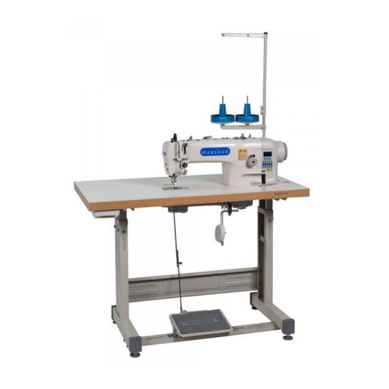
© ANITA 3. BRIEF INTRODUCTION OF THE MACHINE Direct drive heavy duty computer controlled top and bottom feed auto trimmer lockstitch machine with single straight needle. It adopts link take-up to feed, link thread takes -up structure, rotating hook to form stitch 301. The machine adopts the auto-lubrication oil pump. Free and smooth operation, low noise, little vibration, applied to sewing leather, canvas, heavy duty decoration, ribbon type fabric, such as bag, tents, sofa etc. -
Page 9: Installations Of The Knee Control Devices
© ANITA 6. INSTALLATIONS OF THE KNEE CONTROL DEVICES Turn the presser foot lift spanner (1), to let the presser foot (1) down totally. See Fig.3. Release the screw (3). Tighten the screw (6), and adjust the knee control limited frame, make it turn 2mm. ... -
Page 10: Lubrication
© ANITA 8. LUBRICATION Oil amount: Oil amount must be oiled according to the mark of drip pan. Mark (A) is the highest situation. Mark (B) is the lowest situation. Note that oil amount couldn´t be lower than mark (B). Otherwise all parts of machine will appear heat and dead point for not gaining oil. -
Page 11: Adjusting The Oil In The Pump
© ANITA 10. ADJUSTING THE OIL IN THE PUMP When it's running at low speed, observe the oil window. If you don't see the oil spraying, please turn the oil-supplied regulating plate (1) and cover the oil hole (2). See Fig. 7. Figure 7 11. -
Page 12: Winding The Bobbin Thread
© ANITA 13. WINDING THE BOBBIN THREAD Turn on the power. Insert the bobbin core into the bottom of bobbin winder. See Fig. (10). According to the arrow direction. Please winder the thread on the bobbin core for several circles. ... -
Page 13: Threading Upper Thread
© ANITA 15. T HREADING UPPER THREA HREADING UPPER THREA D Before wear line please let take - - up, lever rose to the highest position, lever rose to the highest position, so easy to thread and can prevent so easy to thread and can prevent the start sewing line fall from the the start sewing line fall from the pinhole. -
Page 14: Adjust The Thread Tension
© ANITA 18. ADJUST THE THREAD TENSION Figure 15 Bottom thread tension: Adjust the bobbin thread tension by turning screw (1). Pinch the thread lift the bobbin case. It can use when bobbin case fall freely and slowly. See Fig. (15). Upper thread tension: thread tension will appear the Finished to adjust the bobbin thread tension then adjust the upper... -
Page 15: Adjust The Length Of The Thread After Trimming
© ANITA 20. ADJUST THE LENGTH OF THE THREAD AFTER TRIMMING By turning a small thread clamp nut (1). To adjust. See Fig. (17). • When the shear line, the line is loose, line only small thread clamp device provided by the tension. •... -
Page 16: Adjust The Thread Hook
© ANITA 22. ADJUST THE THREAD HOOK Casing thread (1) hook screw (2) is the standard location in chassis line adjusting the center of the range. See Fig. (19). By moving to loosen the screw (2), the first to adjust the position. When sewing thick, to check the chassis line moves to the left (line force will push big). -
Page 17: Adjust The High Of The Feed Dog
© ANITA 25. ADJUST THE HIGH OF THE FEED DOG Feed dog standard angle is: when the feed dog higher than needle plate and in the highest position. Braces concave point (5) on the crank eccentric shaft tags in a horizontal position. -
Page 18: Cleaning
© ANITA 26. CLEANING Lift the pressure foot. Rive the two screws (1), then unload the needle plate (2). See Fig. (23). 1. Use the soft hairbrush to clean the feed dog. 2. Install the needle plate (2) and tighten the two screws (1). 3. -
Page 19: Button Display And Operating Instructions
© ANITA 27. BUTTON DISPLAY AND OPERATING INSTRUCTIONS Name Indicate Icons Execution starting back seam B segment or execution starting back seam (A, B segment) 1 Execution starting back seam (A, B segment) 2 times. Start/End Back- Tacking Selection Execution terminates back seam C segment or execution terminates back seam (C, D segment) 1 Execution terminates back seam (C, D segment) 2 times. -
Page 20: Comparison Table Of Lcd Display Fonts And Actual Fonts. Arabic Numerals
© ANITA LED ON indicate stopping machine at the upper stop Needle stop up and needle position. down keys LED ON indicate stopping machine at the lower stop needle position. Name Indicate LED ON = Presser Foot automatically goes up after trimming. Presser LED ON = Presser Foot automatically goes up after motor stops. -
Page 21: Manually Adjust The Positioning
© ANITA 30. MANUALLY ADJUST THE MANUALLY ADJUST THE POSITIONING: Press and hold Enter the parameter Enter the parameter c ontent, the hand wheel adjustment supreme ontent, the hand wheel adjustment supreme the [S] key to boot needle position (parameter will chase with the hand wheel needle position (parameter will chase with the hand wheel needle position (parameter will chase with the hand wheel into the needle... -
Page 22: User Parameter & Technician Parameter
© ANITA 32. USER PARAMETER & TECHNICIAN PARAMETER: Parameter Parameter Function Range Default Description In the normal screen, press [P] Maximum Sewing Speed (r/S) 100-3700 3700 Maximum speed of machine sewing The Lager the value, the faster to Speed Curve Adjustment (%] 1-100 increase speed UP: Needle Stops at Up Position... - Page 23 © ANITA Parameter Parameter Function Range Default Description Setting Stitches C of End [End Back-Tacking] C, D segment pin Back-Tacking count set Quick Setup from the front, Setting Stitches D of End where the setting is invalid Back-Tacking Anti-pedaling pedals points; 0-1000 voltage Stitch Balance for End Back-...
- Page 24 © ANITA Parameter Parameter Function Range Default Description Please contact the ANITA B Service Center to enter service settings Brake force 0-31 Efforts to stop the machine when selecting Back-seam operation duty 10-90 Back-seam action to periodic power output cycle (%) ON: It will automatic as reverse function Motor stops with a reverse after trimming (angle adjustment according...
- Page 25 © ANITA Machine Protection Switch O: Disable 1: Testing zero signal Testing 2: Testing positive signal Trimming Protection Switch OFF: Disable ON/OFF Testing ON: Enable Backstitch release buffer (ms) 0-500 Slow release delay factor Presser foot release buffer 0-500 Efforts to case foot pressure release time (ms) The needle position correction...
-
Page 26: Error Code Table
© ANITA 33. ERROR CODE TABLE: Error Code Problem Strategies Power Module is faulty Abnormal over current or voltage System will be shut down until the power Resistor is damage or F1 fuse is blown Moto and machine will be shutting down 1) When power on, detected main voltage too low Please check the AC power. -
Page 27: Port Outline Diagram
© ANITA 34. PORT OUTLINE DIAGRAM: The name of each port 14P function port table: - trimming solenoid: 1, 8 - clamp, dial line solenoid: 2, 9 - clothing lights: 4 (signal ground), 11 (+5v) - backstitch manually switch: 5 (sensor signal), 12 (signal ground) - backstitch solenoid: 6, 13 - complement Needle switch: 7 (sensor signal), 14 (signal ground) MP03100EN_180912... - Page 28 Spare Parts List GF-3131-447 MH ANITA B s.r.o. Průmyslová 2453/7 680 01 Boskovice Czech Republic tel: +420 516 454 774 +420 516 453 496 fax: +420 516 452 751 e-mail: info@anita.cz MP03100EN_180625...
- Page 29 © ANITA VERSION CREATED ON APPROVED BY MP03100EN_180625 25. 06. 2018 Jakub Lžičař All rights reserved. Property of Anita B s.r.o. and protected by copyright. The use of this content without written consent of Anita B s.r.o. is prohibited. Copyright © Anita B s.r.o. (2018) MP03100EN_180625...
- Page 30 © ANITA Obsah A. Arm Mechanism (1/2) ......................4 A. Arm Mechanism (2/2) ......................6 B. Needle Bar and Thread Take-up Mechanism (1/2) ..............8 B. Needle Bar and Thread Take-up Mechanism (2/2) .............. 10 C. Feed Mechanism Components (1/2)..................12 C.
-
Page 31: Arm Mechanism (1/2)
© ANITA © ANITA A. ARM MECHANISM (1/ 2) MP03100EN_180625... -
Page 32: Arm Mechanism (2/2)
© ANITA A. ARM MECHANISM (1/2) Ref.No Parts No. Name of parts Description Note Face plate Face plate screw Face plate thread guide Thread guide Face plate thread guide screw Bobbin thread tension assy A6-1 Bobbin thread tension rod A6-2 Screw type tension rod A6-3 Disc for pretension... - Page 33 © ANITA © ANITA A. ARM MECHANISM (2 /2) MP03100EN_180625...
- Page 34 © ANITA A. ARM MECHANISM (2/2) Ref.No Parts No. Name of parts Description Note A24-2 Slide plate spring A24-3 Slide plate screw Needle plate Needle plate screw Bobbin winder unit Screw Screw Knife Bobbin thread tension assy A31-1 Tension nut A31-2 Washer A31-3...
- Page 35 © ANITA © ANITA B. NEEDLE B AR AND THREAD TAKE AR AND THREAD TAKE -UP MECHANISM (1/2) MP03100EN_180625...
-
Page 36: Needle Bar And Thread Take-Up Mechanism (1/2)
© ANITA B. NEEDLE BAR AND THREAD TAKE-UP MECHANISM (1/2) Ref.No Parts No. Name of parts Description Note Arm shaft Rubber plug Collar for arm shaft Set screw Arm shaft bushing (left) Arm shaft bushing (middle) Set screw Needle bearing Oil seal Arm shaft bushing (right) Rubber ring... - Page 37 © ANITA © ANITA B. NEEDLE BAR AND THR EAD TAKE EAD TAKE -UP MECHANISM (2/2) MP03100EN_180625...
- Page 38 © ANITA B. NEEDLE BAR AND THREAD TAKE-UP MECHANISM (2/2) Ref.No Parts No. Name of parts Description Note Loose thread hinge Retaining ring Screw Connect block Screw Screw Washer Ground wire assy Linker Screw Btw-driving-wheel screw MP03100EN_180625...
- Page 39 © ANITA © ANITA C. FEED MECHANISM C OMPONENTS OMPONENTS (1/2) MP03100EN_180625...
-
Page 40: Feed Mechanism Components (1/2)
© ANITA C. FEED MECHANISM COMPONENTS (1/2) Ref.No Parts No. Name of parts Description Note Feed dog Feed bar assembly Washer Shaft for feed bar Screw Feed rock crank Screw Screw Feed rock shaft Type stop ring Collar for feed lifting rock shaft Collar for feed lifting rock shaft Screw Feed rock shaft craned (right) - Page 41 © ANITA © ANITA C. FEED MECHANISM C OMPONENTS OMPONENTS (2/2) MP03100EN_180625...
- Page 42 © ANITA C. FEED MECHANISM COMPONENTS (2/2) Ref.No Parts No. Name of parts Description Note Screw Spring stand Dial face Screw Stopper pin Spring for stopper pin Dial stopper pin Screw Feed shaft connecting rod Rocker shaft connecting rod Feed regulator connecting rod Walking foot pin Walking foot link Screw...
-
Page 43: Feed Mechanism (1/2)
© ANITA © ANITA D. FEED MECHANISM (1/2) (1/2) MP03100EN_180625... - Page 44 © ANITA D. FEED MECHANISM (1/2) Ref.No Parts No. Name of parts Description Note Spacer Washer Guide shaft Needle of bearing Working foot Screw Screw Spacer Holder for walking foot bar Link of walking foot Screw Fork lever Crank shaft complete Presser swing crank (left) Screw Screw...
-
Page 45: Feed Mechanism (2/2)
© ANITA © ANITA D. FEED MECHANISM (2/2) (2/2) MP03100EN_180625... - Page 46 © ANITA D. FEED MECHANISM (2/2) Ref.No Parts No. Name of parts Description Note Eccentric cam Screw Link complete Screw Link Screw Pear crank Rear bushing Screw Split ring Washer Link adjusting crank Presser foot Elevator shaft Rear bushing Screw Collar for presser swing shaft Screw Front bushing...
- Page 47 © ANITA © ANITA E. PRESSER FOOT M ECHANISM ECHANISM MP03100EN_180625...
-
Page 48: Presser Foot Mechanism
© ANITA E. PRESSER FOOT MECHANISM Ref.No Parts No. Name of parts Description Note Presser bar lifter Set screw Presser bar lifting cam O-ring Scar Tension releasing cam Scar Hinge screw Knee lifter rod Bolt Gasket Spring Knee lifter connecting rod Pin for spring Protective hook Presser bar bushing... - Page 49 © ANITA © ANITA F. ROTARY HOOK M ECHANISM ECHANISM MP03100EN_180625...
-
Page 50: Rotary Hook Mechanism
© ANITA F. ROTARY HOOK MECHANISM Ref.No Parts No. Name of parts Description Note Vertical shaft Bevel gear for arm shaft Set screw Bevel gear for vertical shaft (upper) Bevel gear for hook shaft Bevel gear for vertical shaft (lower) Vertical shaft bushing (upper) Vertical shaft bushing (lower) Set screw... - Page 51 © ANITA © ANITA G. THREAD TRIMMER M ECHANISM ECHANISM (1/2) MP03100EN_180625...
-
Page 52: Thread Trimmer Mechanism (1/2)
© ANITA G. THREAD TRIMMER MECHANISM (1/2) Ref.No Parts No. Name of parts Description Note Drive plate Flexible support plate Screw Flexible connecting plate Screw Drive plate shaft Drive plate spring Drive plate Shaft locking ring Screw Screw Thread electromagnet drive asm Screw Screw Cable clip... - Page 53 © ANITA © ANITA G. THREAD TRIMMER M ECHANISM ECHANISM (2/2) MP03100EN_180625...
- Page 54 © ANITA G. THREAD TRIMMER MECHANISM (2/2) Ref.No Parts No. Name of parts Description Note Thread shear cam crank Spring end cover Spring Locking plate Screw Stopper Spring Screw Cam retaining ring Washer The tangent cam left crank Screw Roller Magnetic plug cushion mat Sealing washer (big) Screw...
-
Page 55: Lubrication
© ANITA © ANITA H. LUBRICATION MP03100EN_180625... - Page 56 © ANITA H. LUBRICATION Ref.No Parts No. Name of parts Description Note Oil pump body Big gear for oil pump Small gear for oil pump Screw Oil pump felting plate Adjusting plate oil pump Oil pump screen complete Screw Shaft for oil pump Screw Spring washer Screw...
- Page 57 © ANITA © ANITA I. REVERSE FEED C OMPONENTS OMPONENTS MP03100EN_180625...
-
Page 58: Reverse Feed Components
© ANITA I. REVERSE FEED COMPONENTS Ref.No Parts No. Name of parts Description Note Reverse feed magnet assy Screw Reverse feed magnet Connecting rod pin Connecting rod Crank Screw Crank pin Reverse feed switch assy Organic glass Lamp Switch contact member Reverse feed switch wire Card line board Switch Box... - Page 59 © ANITA © ANITA J. INBUILT FOOT LIFT ST RUCTURE RUCTURE MP03100EN_180625...
-
Page 60: Inbuilt Foot Lift Structure
© ANITA J. INBUILT FOOT LIFT STRUCTURE Ref.No Parts No. Name of parts Description Note Bolt Spring gasket Left carriage Screw 3/16x28 L=9 Foot lift electromagnet Right carriage Rubber cushion A Rubber cushion B Washer Top column Auto foot lift after lever Retaining ring external Washer Nylon roller pin... - Page 61 © ANITA © ANITA K. IM PACT CONTROLLER SYST PACT CONTROLLER SYST EM MP03100EN_180625...
-
Page 62: Impact Controller System
© ANITA K. IMPACT CONTROLLER SYSTEM Ref.No Parts No. Name of parts Description Note Motor asm Spring gasket Gasket Socket head screw Heat sink Circuit board Cross recess head screw Power panel ST2.9x6,5 Back shroud Casing connection screws Insulating barrier Digital display small plate Operating the mask Set screw... -
Page 63: Accessories
© ANITA © ANITA L. ACCESSORIES MP03100EN_180625... - Page 64 © ANITA L. ACCESSORIES Ref.No Parts No. Name of parts Description Note Parts bag Screw driver (small) Screw driver (middle) Screw driver (large) Needle Bobbin The power cord Oil reservoir Screw Washer Gasket Knee press lifter rod Magnet Oil pot Hinge Rubber coat Cushion (big)
Need help?
Do you have a question about the GF-3131-447 MH and is the answer not in the manual?
Questions and answers