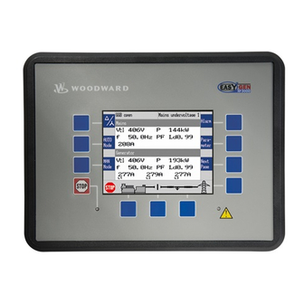
Page 3
The control units can be used in applications such as: co-genera‐ tion, stand-by, AMF, peak shaving, import/export or distributed generation. The easYgen-3000 Series is also applicable for island, island par‐ allel, mains parallel and multiple unit mains parallel operations. 37532G...
Page 4
Brief Overview Sample application setup Fig. 2: Sample application setup A typical application mode for the control unit is the use for mains parallel operation. In this case, the easYgen will function as an engine control with generator, mains and engine protection. The control unit can open and close the generator circuit breaker (GCB) and the mains circuit breaker (MCB).
Page 5
Brief Overview easYgen-3100/3200 Package P1 Package P2 Freely configurable PID controllers — External discrete inputs / outputs via CANopen 16 / 16 32 / 32 (maximum) External analog inputs / outputs via CANopen — 16 / 4 (maximum) Scope of delivery The following parts are included in the scope of delivery.
Page 6
Brief Overview easYgen-3100/3200 P1/P2 | Genset Control 37532G...
Table of contents Table of contents General Information........................ 17 About This Manual........................17 1.1.1 Revision History........................17 1.1.2 Depiction Of Notes And Instructions..................23 Copyright And Disclaimer......................24 Service And Warranty....................... 25 Safety............................25 1.4.1 Intended Use..........................25 1.4.2 Personnel..........................26 1.4.3 General Safety Notes........................
Page 8
Table of contents 3.3.12 Analog Inputs (0 to 500 Ohm | 0/4 to 20 mA)................74 3.3.13 Analog Outputs.......................... 77 3.3.13.1 Analog Outputs (±20 mA, ± 10 V, PWM).................. 77 3.3.14 Serial Interfaces........................78 3.3.14.1 RS-485 Interface........................78 3.3.14.2 RS-232 Interface........................79 CAN Bus Interfaces........................
Page 11
Table of contents 4.5.12 Configure Controller........................ 300 4.5.12.1 Frequency Control........................302 4.5.12.2 Load Control..........................308 4.5.12.3 Derating (Uprating) Of Power ....................315 4.5.12.4 Frequency Depending Derating Of Power................321 4.5.12.5 Voltage Control........................323 4.5.12.6 Power Factor Control......................328 4.5.12.7 Load Share Control......................... 336 4.5.12.8 PID {x} Control.........................
Page 12
Table of contents 5.2.4 Specialised Menu Screens...................... 401 5.2.4.1 Main Screen Voltage Display....................401 5.2.4.2 Alarm List..........................402 5.2.4.3 Sequencing..........................403 5.2.4.4 States easYgen........................404 5.2.4.5 Setpoints..........................404 5.2.4.6 PID1 - PID3 ..........................405 5.2.4.7 Synchroscope (Generator/Busbar And Busbar/Mains)............406 5.2.4.8 LogicsManager Conditions......................
Page 13
Table of contents 6.4.5.2 Setting Up A Test With Or Without Load................. 438 6.4.5.3 Remote Start/Stop, Shutdown, And Acknowledgement............439 6.4.6 Connecting An IKD 1 On CAN Bus 1..................442 6.4.7 Configuring A PWM Duty Cycle For A CAT ADEM Controller..........447 6.4.8 Connecting A GSM Modem.....................
Page 14
Table of contents CAN Interfaces........................522 7.2.1 CAN Interface 1 (Guidance level).................... 522 7.2.2 CAN Interface 2 (Engine level)....................522 Serial Interfaces........................523 7.3.1 RS-232 Interface (Serial Interface 1)..................523 7.3.2 RS-485 Interface (Serial Interface 2)..................524 CANopen Protocol........................524 J1939 Protocol........................
Page 16
Table of contents 9.4.3 Logical Outputs........................693 9.4.4 Logical Command Variables....................697 9.4.4.1 Group 00: Flags Condition 1....................698 9.4.4.2 Group 01: Alarm System......................703 9.4.4.3 Group 02: Systems Condition....................703 9.4.4.4 Group 03: Engine Control......................705 9.4.4.5 Group 04: Applications Condition.................... 707 9.4.4.6 Group 05: Engine Related Alarms...................
General Information About This Manual > Revision History General Information About This Manual 1.1.1 Revision History Rev. Date Editor Changes 2015-11-09 Describes software version 1.2112 and ToolKit version 4.7.3 2nd trigger added for additional (decoupling) ramp after “Frequency depending derating of power”...
Page 18
General Information About This Manual > Revision History Rev. Date Editor Changes Manual Updated according to the changes described above Ä Chapter Derating/uprating of power described in more detail: Refer to 4.5.12.3 “Derating (Uprating) Of Power ” on page 315 . Minor (typo) corrections 2014-02-17 Describes software version 1.2102 and ToolKit version 4.4...
Page 19
General Information About This Manual > Revision History Rev. Date Editor Changes 2013-09-12 New device features & updates with software version 1.2005 The easYgen provides LogicsManager equations to release frequency control LM 00.96 and/or voltage control LM 00.97. The operator can now from outside determine when which control is executed.
Page 20
General Information About This Manual > Revision History Rev. Date Editor Changes The remote control word 503 is equipped with the "Shut-Down-Command" (Bit 9). Refer to Ä “ Bit enabling via Modbus protocol and RS-485 interface” on page 441 for details. The operating range monitor ( Ä...
Page 21
General Information About This Manual > Revision History Rev. Date Editor Changes 2012-12-03 New device features & updates with software version 1.2004 The mains decoupling thresholds are displayed according to VDE-AR-N 4105. Refer to Ä Chapter 5.2.4 “Specialised Menu Screens” on page 401 for details. A button (menu item) for testing the Decoupling Facility is included according to VDE-AR-N 4105.
Page 22
General Information About This Manual > Revision History Rev. Date Editor Changes 2012-03-12 Manual Minor corrections New device features & updates Requirements: easYgen-3100/3200 genset control with software version 1.2002 or higher. The described changes relate to the previous software version 1.2001. Feature updates Ä...
General Information About This Manual > Depiction Of Notes And Ins... Rev. Date Editor Changes Ä Chapter 4.4.2.10 “Change Of Frequency” Change of frequency monitoring. Refer to on page 159 for details. The setting range resolution of "Delay" (parameter 3105 Ä p. 162) has been changed from 0.1 s to 0.01 s.
Warranty terms Please enquire about the terms of warranty from your nearest Woodward representative. For our contact search webpage please go to: http://www.woodward.com/Directory.aspx Safety 1.4.1...
General Information Safety > Personnel 1.4.2 Personnel WARNING! Hazards due to insufficiently qualified personnel! If unqualified personnel perform work on or with the control unit hazards may arise which can cause serious injury and substantial damage to property. – Therefore, all work must only be carried out by appropriately qualified personnel.
Device implemented self test this Woodward device has a self test check implemented. Perma‐ nently under control are: processor function and supply voltage. This internal signal "self check" is aligned in series with the inverse signal "Ready for op.
Page 28
General Information Safety > General Safety Notes Be careful in changing safety relevant settings! CAUTION! Uncontrolled operation due to faulty configuration The discrete output "Ready for operation OFF" must be wired in series with an emergency stop function. This means that it must be ensured that the generator circuit breaker is opened and the engine is stopped if this discrete output is de-energized.
Page 29
General Information Safety > General Safety Notes Electrostatic discharge Protective equipment: ESD wrist band NOTICE! Damage from electrostatic discharge All electronic equipment sensitive to damage from electrostatic discharge, which can cause the control unit to malfunction or fail. – To protect electronic components from static damage, take the precautions listed below.
Safety > Protective Equipment And T... For additional information on how to prevent damage to electronic components caused by improper han‐ dling, read and observe the precautions in: "Woodward manual 82715, Guide for Handling and – Protection of Electronic Controls, Printed Circuit Boards, and Modules".
Page 31
General Information Safety > Protective Equipment And T... Certain tasks presented in this manual require the personnel to wear protective equipment. Specific required equipment is listed in each individual set of instructions. The cumulative required personal protective equipment is detailed below: ESD wrist band The ESD (electrostatic discharge) wrist band keeps the user's...
Page 32
General Information Safety > Protective Equipment And T... easYgen-3100/3200 P1/P2 | Genset Control 37532G...
Ä Chapter 5 “Operation” on page 383 provides information on how to access the unit via the front panel or remotely using the ToolKit software provided by Woodward. Ä Chapter 6 “Application” on page 417 provides application examples as well as instructions for the corresponding required configuration.
An alarm is "present" when it is active or latched (trig‐ gered). Hardware Interfaces (Terminals) The easYgen-3100/3200 (Fig. 6) provides the following terminals. Fig. 6: easYgen-3000 Series (housing variants) A easYgen-3200 (plastic housing with display) CAN bus interface connector #2 B easYgen-3100 (sheet metal housing)
System Overview Application Modes Overview Application Modes Overview The genset control provides the following basic functions via the application modes listed below. For detailed information on the application modes and special applications refer to Ä Chapter 6 “Application” on page 417. Application mode Symbol Function...
Page 36
System Overview Application Modes Overview easYgen-3100/3200 P1/P2 | Genset Control 37532G...
Installation Mount Unit (Sheet Metal Hous... Installation Mount Unit (Sheet Metal Housing) Dimensions 84 mm 250 mm Fig. 7: Sheet metal housing - dimensions 37532G easYgen-3100/3200 P1/P2 | Genset Control...
Page 38
Installation Mount Unit (Sheet Metal Hous... Mounting into a cabinet Special tool: Torque screwdriver Proceed as follows to install the unit using the screw kit: Fig. 8: Sheet metal housing - drill plan Drill the holes according to the dimensions in Fig. 8 (dimen‐ sions shown in mm).
Installation Mount Unit (Plastic Housing) Mount Unit (Plastic Housing) Ä Chapter Mount the unit either using the clamp fasteners ( 3.2.1 “Clamp Fastener Installation” on page 40 ) or the screw kit Ä Chapter 3.2.2 “Screw Kit Installation” on page 41 ). Don't drill holes if you want to use the clamp fas‐...
Installation Mount Unit (Plastic Housing) > Clamp Fastener Installation The maximum permissible corner radius is 4 mm. 3.2.1 Clamp Fastener Installation For installation into a door panel with the fastening clamps, pro‐ ceed as follows: Cut out the panel according to the dimensions in Fig. 10. Don't drill the holes if you want to use the clamp fasteners.
Installation Mount Unit (Plastic Housing) > Screw Kit Installation Tighten the clamping screws (Fig. 14/1) until the control unit is secured to the control panel (Fig. 14/2). Over tightening of these screws may result in the clamp inserts or the housing breaking.
Installation Setup Connections > Terminal Allocation Special tool: Torque screwdriver Proceed as follows to install the unit using the screw kit: Cut out the panel and drill the holes according to the dimen‐ sions in Fig. 16 (dimensions shown in mm). Insert the unit into the panel cutout.
Installation Setup Connections > Wiring Diagram Fig. 17: easYgen-3200 plastic housing Fig. 18: easYgen-3100 sheet metal housing 3.3.2 Wiring Diagram The Protective Earth terminal 61 is not connected on the sheet metal housing. Use the protective earth (PE) connector located at –...
PE is not possible, it is recommended to use an isolated external power supply if the differential voltage between battery minus and PE exceeds 40 V. Woodward recommends to use one of the following slow-acting protective devices in the supply line to ter‐ minal 63: Fuse NEOZED D01 6A or equivalent or –...
The control unit will not measure voltage correctly if the 120 V and 480 V inputs are utilized simultaneously. – Never use both sets of voltage measuring inputs. Woodward recommends protecting the voltage meas‐ uring inputs with slow-acting fuses rated for 2 to 6 A. 3.3.5.1 Generator Voltage...
Page 48
Installation Setup Connections > Voltage Measuring > Generator Voltage Terminal Description Generator voltage - L1 120 Vac 2.5 mm² 480 Vac 2.5 mm² Generator voltage - L2 120 Vac 2.5 mm² 480 Vac 2.5 mm² Generator voltage - L3 120 Vac 2.5 mm²...
Page 49
Installation Setup Connections > Voltage Measuring > Generator Voltage Measuring inputs Fig. 24: Measuring inputs - 3Ph 4W OD Terminal assignment 3Ph 4W OD Wiring terminals Rated voltage (range) 120 V (50 to 130 V 480 V (131 to 480 V eff.
Page 50
Installation Setup Connections > Voltage Measuring > Generator Voltage Measuring inputs Fig. 25: Measuring inputs - 3Ph 4W Terminal assignment 3Ph 4W Wiring terminals Rated voltage (range) 120 V (50 to 130 V 480 V (131 to 480 V eff. eff.
Page 51
Installation Setup Connections > Voltage Measuring > Generator Voltage Measuring inputs Fig. 26: Measuring inputs - 3Ph 3W Terminal assignment 3Ph 3W Wiring terminals Rated voltage (range) 120 V (50 to 130 V 480 V (131 to 480 V eff. eff.
Page 52
Installation Setup Connections > Voltage Measuring > Generator Voltage Measuring inputs Fig. 27: Measuring inputs - 1Ph 3W Terminal assignment 1Ph 3W Wiring terminals Rated voltage (range) 120 V (50 to 130 V 480 V (131 to 480 V eff. eff.
Page 53
Installation Setup Connections > Voltage Measuring > Generator Voltage '1Ph 2W' Phase-Neutral Measuring Generator windings Table 11: Generator windings - 1Ph 2W (phase neutral) Measuring inputs Fig. 28: Measuring inputs - 1Ph 2W (phase neutral) Terminal assignment 1Ph 2W Wiring terminals Rated voltage (range) 120 V (50 to 130 V 480 V (131 to 480 V...
Page 54
Installation Setup Connections > Voltage Measuring > Generator Voltage '1Ph 2W' Phase-Phase Measuring Generator windings Table 12: Generator windings - 1Ph 2W (phase-phase) Measuring inputs Fig. 29: Measuring inputs - 1Ph 2W (phase-phase) Terminal assignment 1Ph 2W Wiring terminals Rated voltage (range) 120 V (50 to 130 V 480 V (131 to 480 V eff.
Installation Setup Connections > Voltage Measuring > Mains Voltage 3.3.5.2 Mains Voltage General notes If parameter 1803 Ä p. 101 ("Mains PT secondary rated volt.") is configured with a value between 50 and 130 V, the 120 V input terminals must be used for proper measurement.
Page 56
Installation Setup Connections > Voltage Measuring > Mains Voltage 3.3.5.2.1 Parameter Setting '3Ph 4W' (3-phase, 4-wire) Mains windings Table 14: Mains windings - 3Ph 4W Measuring inputs Fig. 31: Measuring inputs - 3Ph 4W Terminal assignment 3Ph 4W Wiring terminals Rated voltage (range) 120 V (50 to 130 V 480 V (131 to 480 V...
Page 57
Installation Setup Connections > Voltage Measuring > Mains Voltage 3.3.5.2.2 Parameter Setting '3Ph 3W' (3-phase, 3-wire) Mains windings Table 15: Mains windings - 3Ph 3W Measuring inputs Fig. 32: Measuring inputs - 3Ph 3W Terminal assignment 3Ph 3W Wiring terminals Rated voltage (range) 120 V (50 to 130 V 480 V (131 to 480 V...
Page 58
Installation Setup Connections > Voltage Measuring > Mains Voltage 3.3.5.2.3 Parameter Setting '1Ph 3W' (1-phase, 3-wire) Mains windings Table 16: Mains windings - 1Ph 3W Measuring inputs Fig. 33: Measuring inputs - 1Ph 3W Terminal assignment 1Ph 3W Wiring terminals Rated voltage (range) 120 V (50 to 130 V 480 V (131 to 480 V...
Page 59
Installation Setup Connections > Voltage Measuring > Mains Voltage 3.3.5.2.4 Parameter Setting '1Ph 2W' (1-phase, 2-wire) The 1-phase, 2-wire measurement may be performed phase-neutral or phase-phase. Please note to configure and wire the easYgen – consistently. '1Ph 2W' Phase-Neutral Measuring Mains windings Table 17: Mains windings - 1Ph 2W (phase neutral) Measuring inputs...
Page 60
Installation Setup Connections > Voltage Measuring > Mains Voltage For different voltage systems, different wiring terminals have to be used. Incorrect measurements are possible, if both voltage systems use the same N terminal. '1Ph 2W' Phase-Phase Measuring Mains windings Table 18: Mains windings - 1Ph 2W (phase-phase) Measuring inputs Fig.
Installation Setup Connections > Voltage Measuring > Busbar Voltage 3.3.5.3 Busbar Voltage General notes If parameter 1812 Ä p. 100 ("Busb1 PT secondary rated volt.") is configured with a value between 50 and 130 V, the 120 V input terminals must be used for proper measurement.
Page 62
Installation Setup Connections > Voltage Measuring > Busbar Voltage '1Ph 2W' Phase-Neutral Measuring Busbar windings Table 20: Busbar windings - 1Ph 2W (phase neutral) Measuring inputs Fig. 37: Measuring inputs - 1Ph 2W (phase neutral) Terminal assignment 1Ph 2W Wiring terminals Rated voltage (range) 120 V (50 to 130 V 480 V (131 to 480 V...
Page 63
Installation Setup Connections > Voltage Measuring > Busbar Voltage '1Ph 2W' Phase-Phase Measuring Busbar windings Table 21: Busbar windings - 1Ph 2W (phase-phase) Measuring inputs Fig. 38: Measuring inputs - 1Ph 2W (phase-phase) Terminal assignment 1Ph 2W Wiring terminals Rated voltage (range) 120 V (50 to 130 V 480 V (131 to 480 V eff.
Installation Setup Connections > Current Measuring > Generator Current 3.3.6 Current Measuring 3.3.6.1 Generator Current General notes WARNING! Dangerous voltages due to missing load – Before disconnecting the device, ensure that the current transformer (CT) is short-circuited. Generally, one line of the current transformers secon‐ dary must be grounded close to the CT.
Installation Setup Connections > Current Measuring > Mains Current Wiring terminals Terminal Phase — — — — s2 (l) L3 s1 (k) 3.3.6.2 Mains Current General notes WARNING! Dangerous voltages due to missing load – Before disconnecting the device, ensure that the current transformer (CT) is short-circuited.
Installation Setup Connections > Power Factor Definition 3.3.8 Power Factor Definition Definition Power Factor is defined as a ratio of the real power to apparent power. In a purely resistive circuit, the voltage and current wave‐ forms are instep resulting in a ratio or power factor of 1.00 (often referred to as unity).
Installation Setup Connections > Magnetic Pickup Unit (MPU) Phasor diagram The phasor diagram is used from the generator's view. Inductive Capacitive Diagram 3.3.9 Magnetic Pickup Unit (MPU) General notes The shield of the MPU (Magnetic Pickup Unit) connec‐ tion cable must be connected to a single point ground terminal near the easYgen.
Installation Setup Connections > Relay Outputs (LogicsManag... In the state N.C., a potential is continuously present during normal operation; if an alarm is issued or control operation is performed, the input is de-energized. The N.O. or N.C. contacts may be connected to the signal terminal Ä...
Installation Setup Connections > Analog Inputs (0 to 500 Oh... Terminal Description N.O. Common Form A Relay output [R 08] 2.5 mm² LogicsManager Preconfigured to "Command: close MCB" Relay output [R 09] 2.5 mm² Preconfigured to "Mains decoupling" Preconfigured to "Command: open MCB" Relay output [R 10] 2.5 mm²...
Page 75
Installation Setup Connections > Analog Inputs (0 to 500 Oh... Linear Pt100 VDO 120° C VDO 150° C VDO 10 bar VDO 5 bar The 9 setpoints of the free configurable Tables A and B can be selected for Type definition (parameters 1000, 1050, and 1100). A catalog of all available VDO sensors is available for download at the VDO homepage (http://www.vdo.com) Wiring two-pole senders...
Page 76
Installation Setup Connections > Analog Inputs (0 to 500 Oh... Terminal Description Analog input [AI 01] ground, connected with PE 2.5 mm² Analog input [AI 01] 2.5 mm² Analog input [AI 02] ground, connected with PE 2.5 mm² Analog input [AI 02] 2.5 mm²...
Installation Setup Connections > Analog Outputs > Analog Outputs (±20 mA, ± ... Terminal Description Analog input [AI 03] ground, connected with engine 2.5 mm² ground Analog input [AI 03] 2.5 mm² Wiring single and two-pole senders It is possible to combine single- and two-pole senders but with the simultaneously Ä...
Installation Setup Connections > Serial Interfaces > RS-485 Interface In case that higher permanent insulation voltages are required than described in the technical data, please install isolation equipment (isolation amplifier) for proper and safe operation. CAUTION! Connecting external power sources to the analog out‐ puts may damage the device.
Installation Setup Connections > Serial Interfaces > RS-232 Interface RS-485 half-duplex Fig. 60: RS-485 - connection for half-duplex operation RS-485 full-duplex Fig. 61: RS-485 - connection for full-duplex operation Shielding easYgen is prepared for shielding: Terminal 1 and the connector housing are internally grounded via an RC element.
Installation CAN Bus Interfaces Terminal Description CTS (clear to send) Not connected Table 27: Pin assignment CAN Bus Interfaces Pin assignment Terminal Description Not connected CAN-L Fig. 64: SUB-D connector - pins Not connected Connected with con‐ nector housing and inter‐ nally grounded via RC element Not connected...
Page 81
Installation CAN Bus Interfaces For very critical EMC conditions (many noise sources with high noise levels) and for high transmission rates we recommend to use the 'Split termination concept' as shown. Divide the termination resistance into 2x60 Ohms with a center tap connected to ground via a capacitor of 10 to 100 nF (Fig.
Installation Connecting 24 V Relays Woodward recommends the use of shielded, twisted- pair cables for the CAN bus (see examples). – Lappkabel Unitronic LIYCY (TP) 2×2×0.25 UNITRONIC-Bus LD 2×2×0.22 – Connecting 24 V Relays NOTICE! Damage to adjacent electronic components due to induced voltages –...
Page 83
Installation Connecting 24 V Relays Advantages and disadvantages of different interference sup‐ pressing circuits are as follows: Connection diagram Load current / voltage curve Advantages Disadvantages Uncritical dimensioning High release delay Lowest possible induced voltage Very simple and reliable Uncritical dimensioning No attenuation below VVDR High energy absorption Very simple setup...
Page 84
Installation Connecting 24 V Relays easYgen-3100/3200 P1/P2 | Genset Control 37532G...
Configuration Basic Setup > Configure Language/Clock Configuration All parameters are assigned a unique parameter identification number. The parameter identification number may be used to reference individual parameters listed in this manual. This parameter identification number is also displayed in the ToolKit configuration screens next to the respec‐ tive parameter.
Page 86
Configuration Basic Setup > Configure Language/Clock Parameter Setting range Description [Default] Example 0 = 0th second of the minute 59 = 59th second of the minute 1711 day 1 to 31 The day of the date is set here. [real-time clock] Example 1 = 1st day of the month.
Page 87
Configuration Basic Setup > Configure Language/Clock Parameter Setting range Description [Default] Notes This parameter is only displayed, if Daylight saving time (param‐ eter 4591 Ä p. 86) is set to "On". 4598 DST begin Sunday to Sat‐ The weekday for the DST begin date is configured here weekday urday Notes...
Page 88
Configuration Basic Setup > Configure Language/Clock Parameter Setting range Description [Default] 4595 DST end nth. The order number of the weekday for the DST begin date is configured here. weekday [1st] DST ends on the 1st configured weekday of the DST begin month. DST ends on the 2nd configured weekday of the DST begin month.
Configuration Basic Setup > Enter Password USA, Canada European Union Year DST Begins 2 DST Ends 2 DST Begins 1 DST Ends 1 a.m. (Second a.m. (First a.m. a.m. Sunday in Sunday in UTC=GMT UTC=GMT March) November) (Last Sunday (Last Sunday in March) in October) 2008...
Page 90
Configuration Basic Setup > Enter Password Code level Code level CL0 (User This code level permits for monitoring of the system Level) and limited access to the parameters. Standard password = Configuration of the control is not permitted. none Only the parameters for setting the language, the date, the time, and the horn reset time are acces‐...
Page 91
Configuration Basic Setup > Enter Password Code level display The current code level is indicated by the lock symbol in the config‐ uration menu screens. The lock symbol indicates the number of the code level and appears as "locked" (in code level CL0) or "unlocked"...
Configuration Basic Setup > System Management 4.1.5 System Management Parameter Setting range Description [Default] 1702 Device number 1 to 32 A unique address is assigned to the control though this parameter. This unique address permits the controller to be correctly identified on the CAN bus.
10417 Ä p. 92/Ä p. 518) is set to "Yes". This parameter is not available via ToolKit. This function is used for uploading application software and may only be used by authorized Woodward service personnel! 1706 Clear eventlog The event history will be cleared.
Configuration Configure Measurement Configure Measurement General notes If the easYgen is intended to be operated in parallel with the mains, the mains voltage measuring inputs must be connected. Dependencies PF Power Factor Active Power [kW] Apparent power [kVA] Reactive Power [kvar] The AC power triangle illustrates the dependencies between active power, apparent power, reactive power and power factor.
Page 95
Configuration Configure Measurement Parameter Setting range Description [Default] Recommended settings The asynchronous modus is normally used in mains parallel operation. Please consider the following settings: Application mode (parameter 3401 Ä p. 222) = GCB MPU input (parameter 1600 Ä p. 274) = On Generator operating frequency (parameter 5802 Ä...
Page 96
Configuration Configure Measurement Parameter Setting range Description [Default] 1746 Mains rated 0.5 to 99999.9 This value specifies the mains reactive power rating, which is used as a refer‐ react. pwr. kvar ence figure for related functions. [kvar] [200.0 kvar] The mains rated reactive power is a reference value used by several moni‐ Ä...
Page 97
Configuration Configure Measurement Parameter Setting range Description [Default] 1Ph 2W Measurement is performed Line-Neutral (WYE connected system) if param‐ eter 1858 Ä p. 96 is configured to "Phase - neutral" and Line-Line (Delta con‐ nected system) if parameter 1858 Ä p. 96 is configured to "Phase - phase".
Page 98
Configuration Configure Measurement Parameter Setting range Description [Default] 1853 Mains voltage [3Ph 4W] Measurement is performed Line-Neutral (WYE connected system) and Line- measuring Line (Delta connected system). The protection depends on the setting of parameter 1771 Ä p. 139. Phase voltages and the neutral must be connected for proper calculation. Measurement, display and protection are adjusted according to the rules for WYE connected systems.
Configuration Configure Measurement > Configure Transformer Parameter Setting range Description [Default] 1852 Mains current [Phase L1] / Phase L{1/2/3} Measurement is performed for the selected phase only. The measuring Phase L2 / measurement and display refer to the selected phase. Phase L3 The configured phase CT must be connected to perform current measure‐...
Page 100
Configuration Configure Measurement > Configure Transformer Parameter Setting range Description [Default] Notes WARNING: Only connect the measured voltage to either the 120 Vac or the 480 Vac inputs. Do not connect both sets of inputs to the measured system. The control unit is equipped with dual voltage measuring inputs. The voltage range of these measurement inputs is dependent upon input terminals are used.
Page 101
Configuration Configure Measurement > Configure Transformer Parameter Setting range Description [Default] 1803 Mains PT sec‐ 50 to 480 V Some applications may require the use of potential transformers to facilitate ondary rated measuring the mains voltages. The rating of the secondary side of the poten‐ [400 V] volt.
Configuration Configure Measurement > External Mains Active Power 4.2.2 External Mains Active Power Parameter Setting range Description [Default] 2966 External mains The mains active power is coming from an external source. active power The following measurement values of the external mains active power depend on the external mains reactive power measurement.
Configuration Function Of Inputs And Outpu... > Discrete Inputs 4.2.3 External Mains Reactive Power Parameter Setting range Description [Default] 2969 External mains The mains reactive power is coming from an external source. This power is reactive power displayed and used for control purposes. The source is taken via Analog‐ Manager.
Page 104
Configuration Function Of Inputs And Outpu... > Discrete Inputs Programmable – The discrete input has been assigned a default function using either the LogicsManager or preconfigured alarms such as "emergency stop". – The following sections describe how these functions are assigned.
Page 105
Configuration Function Of Inputs And Outpu... > Discrete Inputs Input Type/Preset Description Discrete input [DI 07] Fixed to "Reply: MCB open" Only applicable for application mode This input implements negative function logic. The controller utilizes the CB auxiliary (B) contacts into this dis‐ crete input to reflect the state of the MCB.
Configuration Function Of Inputs And Outpu... > Discrete Outputs 4.3.2 Discrete Outputs Programmable – The discrete output has been assigned a default function using the LogicsManager. – The following text describes how these functions are assigned using the LogicsManager. – It is possible to change the function of the discrete output if required.
Page 107
Configuration Function Of Inputs And Outpu... > Discrete Outputs CAUTION! Uncontrolled operation due to unknown configura‐ tion The circuit breaker commands must be checked before every commissioning because the relays can be used for different applications and can be assigned to various functions.
Page 108
Configuration Function Of Inputs And Outpu... > Discrete Outputs Output Type/Preset Description Relay output [R 05] Programmable Preglow Preconfigured to "Preglow" When this discrete output is enabled, the diesel engine's glow plugs are energized (refer to Ä Chapter 4.5.9.1 “Engine Type” on page 260 ).
Configuration Configure Monitoring > Generator Output Type/Preset Description Relay output [R 08] Programmable Only applicable for application mode Preconfigured to "Command: close MCB" The discrete output "Command: close MCB" is an impulse output signal. This discrete output is enabled for the time configured in param‐ eter 3417 Ä...
Configuration Configure Monitoring > Generator > Generator Overfrequency (L... Parameter Setting range Description [Default] Phase - neutral The phase-neutral voltage will be monitored and all subsequent parameters concerning voltage monitoring "generator" are referred to this value (VL-N). Notes WARNING: This parameter defines how the protective functions operate. 4.4.1.1 Generator Operating Voltage / Frequency The operating voltage/frequency parameters are used...
Page 111
Configuration Configure Monitoring > Generator > Generator Overfrequency (L... If this protective function is triggered, the display indi‐ cates "Gen. overfrequency 1" or "Gen. overfrequency 2" and the logical command variable "06.01" or "06.02" will be enabled. Ä Chapter 9.1.1 “Triggering Characteristics” on page 551 Refer to for the triggering characteristic of this monitoring function.
Configuration Configure Monitoring > Generator > Generator Underfrequency (... Parameter Setting range Description [Default] [No] The control unit does not automatically reset the alarm when the fault condi‐ tion is no longer detected. The alarm must be acknowledged and reset by manually pressing the appro‐ priate buttons or by activating the LogicsManager output "External acknowl‐...
Configuration Configure Monitoring > Generator > Generator Overvoltage (Lev... Parameter Setting range Description [Default] 1954 Limit 50.0 to 130.0 % The percentage values that are to be monitored for each threshold limit are defined here. 1960 1954: [90.0 %] If this value is reached or exceeded for at least the delay time without inter‐ 1960: [84.0 %] ruption, the action specified by the alarm class is initiated.
Page 114
Configuration Configure Monitoring > Generator > Generator Overvoltage (Lev... If this protective function is triggered, the display indi‐ cates "Gen. overvoltage 1" or "Gen. overvoltage 2" and the logical command variable "06.05" or "06.06" will be enabled. Ä Chapter 9.1.1 “Triggering Characteristics” on page 551 Refer to for the triggering characteristic of this monitoring function.
Configuration Configure Monitoring > Generator > Generator Undervoltage (Le... Parameter Setting range Description [Default] 2003 Delayed by Monitoring for fault conditions is not performed until engine delayed moni‐ engine speed toring is enabled. The engine monitoring delay time (param‐ 2009 eter 3315 Ä...
Configuration Configure Monitoring > Generator > Generator Time-Overcurrent... Parameter Setting range Description [Default] (Reset Delay: Notes 80 ms) This value refers to the System rated frequency (parameter 1766 Ä p. 95). 2055 Delay 0.02 to 99.99 s If the monitored generator voltage value falls below the threshold value for the delay time configured here, an alarm will be issued.
Configuration Configure Monitoring > Generator > Generator Reverse/Reduced ... Parameter Setting range Description [Default] 2200 Monitoring [On] Overcurrent monitoring is carried out according to the following parameters. Monitoring is performed at three levels. All three values may be configured 2206 independent from each other (prerequisite: Level 1 <...
Page 118
Configuration Configure Monitoring > Generator > Generator Reverse/Reduced ... If the single-phase or three-phase measured real power is below the configured limit of the reduced load or below the configured value of the reverse power, an alarm will be issued. If this protective function is triggered, the display indi‐...
Configuration Configure Monitoring > Generator > Generator Overload IOP (Le... Parameter Setting range Description [Default] 2250 Monitoring [On] Reverse/reduced power monitoring is carried out according to the following parameters. 2256 Both values may be configured independent from each other (prerequisite for : GCB must be closed).
Page 120
Configuration Configure Monitoring > Generator > Generator Overload IOP (Le... The power produced by the generator is calculated from the voltage and current values measured in accordance with how parameters "Generator voltage measuring" (parameter 1851 Ä p. 96) and "Generator current measuring" (param‐ eter 1850 Ä...
Configuration Configure Monitoring > Generator > Generator Overload MOP (Le... Parameter Setting range Description [Default] 2302 Self acknowl‐ The control automatically clears the alarm if the fault condition is no longer edge detected. 2308 [No] The control does not automatically reset the alarm when the fault condition is no longer detected.
Configuration Configure Monitoring > Generator > Generator Unbalanced Load ... Parameter Setting range Description [Default] (Reset Delay: Notes 80 ms) This value refers to the Generator rated active power (param‐ eter 1752 Ä p. 95). 2355 Delay 0.02 to 99.99 s If the monitored generator load exceeds the threshold value for the delay time configured here, an alarm will be issued.
Configuration Configure Monitoring > Generator > Generator Voltage Asymmetry Parameter Setting range Description [Default] Notes If the monitored current falls below the threshold (minus the hysteresis) before the delay expires the time will be reset. 2401 Alarm class Class Each limit may be assigned an independent alarm class that specifies what A/B/C/D/E/F, action should be taken when the limit is surpassed.
Configuration Configure Monitoring > Generator > Generator Ground Fault (Le... Parameter Setting range Description [Default] 3900 Monitoring [On] Voltage asymmetry monitoring is carried out according to the following parameters. No monitoring is carried out. 3903 Limit 0.5 to 15.0 % The percentage values that are to be monitored for each threshold limit are defined here.
Page 126
Configuration Configure Monitoring > Generator > Generator Ground Fault (Le... Calculated ground fault The current produced by the generator is monitored depending on how parameter "Generator current measuring" (parameter 1850 Ä p. 97) is configured. The measured three conductor cur‐ rents IGen-L1, IGen-L2 and IGen-L3 are vectorially totaled (IS = IGen-L1 + IGen-L2 + IGen-L3) and compared with the configured fault limit (the calculated actual value is indicated in the display).
Page 127
Configuration Configure Monitoring > Generator > Generator Ground Fault (Le... The pointer between the neutral point and the point of the shifted pointer I ' results is the sum current I as shown in (Fig. 70/2). In order to be able to add the pointers vectorially, these must be divided into their X- and Y-coordinates (IL2X, IL2Y, IL3X and IL3Y).
Page 128
Configuration Configure Monitoring > Generator > Generator Ground Fault (Le... Parameter Setting range Description [Default] 3251 Alarm class Class Each limit may be assigned an independent alarm class that specifies what A/B/C/D/E/F, action should be taken when the limit is surpassed. 3257 Control Notes...
Configuration Configure Monitoring > Generator > Generator Phase Rotation 4.4.1.13 Generator Phase Rotation General notes NOTICE! Damage to the control unit and/or generation equipment – Ensure that the control unit is properly connected to phase voltages on both sides of the circuit breaker(s) during installation.
Page 130
Configuration Configure Monitoring > Generator > Generator Phase Rotation The direction of configured rotation being monitored by the control unit is displayed on the screen. If this protective function is triggered, the display indi‐ cates "Gen.ph.rot. mismatch" and the logical command variable "06.21"...
Configuration Configure Monitoring > Generator > Generator Inverse Time-Ove... 4.4.1.14 Generator Inverse Time-Overcurrent ANSI# IEC 255 General notes The current produced by the generator is monitored depending on how parameter "Generator current measuring" (param‐ eter 1850 Ä p. 97) is configured. If an overcurrent condition is detected, the fault recognition time is determined by the configured tripping characteristic curve and the measured current.
Page 133
Configuration Configure Monitoring > Generator > Generator Inverse Time-Ove... Fig. 73: "Extremely inverse" characteristic Parameter Setting range Description [Default] 4030 Monitoring [On] Overcurrent monitoring is carried out according to the following parameters. No monitoring is carried out. 4034 Inverse time Selection of the used overcurrent characteristic.
Configuration Configure Monitoring > Generator > Generator Lagging Power Fa... Parameter Setting range Description [Default] Notes Ä Chapter 9.5.1 “Alarm Classes” For additional information refer to on page 733 4032 Self acknowl‐ The control unit automatically clears the alarm if the fault condition is no edge longer detected.
Page 135
Configuration Configure Monitoring > Generator > Generator Lagging Power Fa... Power Factor Leading (capacitive) Lagging (inductive) More lagging than a leading More lagging than a lagging PF limit of -0.40 PF limit of +0.85 -0.40 +0.85 -0.50 -0.75 1.00 +0.75 +0.50 Import Inductive Power Export Inductive Power...
Configuration Configure Monitoring > Generator > Generator Leading Power Fa... 4.4.1.16 Generator Leading Power Factor (Level 1 & 2) General notes The power factor is monitored for becoming more leading (i.e. capacitive) than an adjustable limit. This limit may be a leading or lagging power factor limit.
Configuration Configure Monitoring > Generator > Generator Voltage Restrain... Parameter Setting range Description [Default] 2380 Delay 0.02 to 99.99 s If the monitored generator power factor is more leading than the configured limit for the delay time configured here, an alarm will be issued. 2386 2380: [30.00 s] Notes...
Page 138
Configuration Configure Monitoring > Generator > Generator Voltage Restrain... Fig. 76: Example for generator voltage restraint overcurrent char‐ acteristic Beginning at a voltage dip of 95% rated voltage (configured by 2231), the modification factor will be linearly reduced (cf. figure 86). If the voltage reaches 25% or less (configured by 2230) the modifi‐...
Configuration Configure Monitoring > Mains > Mains Operating Voltage / ... 4.4.2 Mains Parameter Setting range Description [Default] 1771 Mains voltage The unit can either monitor the wye voltages (phase-neutral) or the delta vol‐ monitoring tages (phase-phase). The monitoring of the wye voltage is above all neces‐ sary to avoid earth-faults in a compensated or isolated network resulting in the tripping of the voltage protection.
Configuration Configure Monitoring > Mains > Mains Decoupling If the rated system frequency is 50 Hz, the lower frequency limit is 90 % (of the rated system frequency, i.e. 45 Hz), and the hyste‐ resis for the lower frequency limit is 5 % (of the rated system fre‐ quency, i.e.
Page 142
Configuration Configure Monitoring > Mains > Mains Decoupling Parameter Setting range Description [Default] MCB->GCB Mains decoupling is carried out according to the following parameters. If one of the subordinate monitoring functions is triggered, the MCB will be opened. If the reply "MCB open" is not present within the delay configured in param‐ eter 3113 Ä...
Page 143
Woodward solves this requirement with the use of a minimum of two units acting as a system. The system allows incorporating more units, so that the availability of the generator can still be increased.
Page 144
Configuration Configure Monitoring > Mains > Mains Decoupling Fig. 77: Select mains decoupling 4105 Monitoring according AR-N-4105 Parameter Setting range Description [Default] 3297 Monitoring [Off] The diagnostic function is disabled, no related monitoring is executed. Off, CAN 1 If the diagnostic function is enabled, the related CAN messages can be received via CAN 1.
Page 145
Configuration Configure Monitoring > Mains > Mains Decoupling Monitoring Parameter Alignment The following parameters are compared for monitoring its align‐ VDE AR-N-4105 ment: Control Parameter ID Parameter Mains Decoupling 3110 Mains Decoupling Overfrequency level 2 2856 Monitoring 2860 Limit 2861 Delay Underfrequency level 2 2906...
Page 146
Configuration Configure Monitoring > Mains > Mains Decoupling Parameter Setting range Description [Default] 5131 Alarm class The alarm class specifies what action should be taken if the parameter aliign‐ ment between the communication devices(s) of the AR-N-4105 system is A to F, control active.
Configuration Configure Monitoring > Mains > Mains Overfrequency (Level... Q(V) Monitoring Mains Time-Dependent Voltage (FRT) The Change of frequency monitors (vector/phase shift or df/dt) is not directly required by BDEW. These monitors are depending on the according network providers. Other functions related to the BDEW guideline: Ä...
Configuration Configure Monitoring > Mains > Mains Underfrequency (Leve... Parameter Setting range Description [Default] Notes This value refers to the System rated frequency (parameter 1750 Ä p. 95). 2855 Delay 0.02 to 99.99 s If the monitored mains frequency value exceeds the threshold value for the delay time configured here, an alarm will be issued.
Configuration Configure Monitoring > Mains > Mains Overvoltage (Level 1... Parameter Setting range Description [Default] 2900 Monitoring [On] Underfrequency monitoring is carried out according to the following parame‐ ters. Monitoring is performed at two levels. 2906 Both values may be configured independent from each other (prerequisite: Level 1 >...
Page 150
Configuration Configure Monitoring > Mains > Mains Overvoltage (Level 1... If this protective function is triggered, the display indi‐ cates "Mains overvoltage 1" or "Mains overvoltage 2" and the logical command variable "07.10" or "07.11" will be enabled. Ä Chapter 9.1.1 “Triggering Characteristics” Refer to on page 551 for the triggering characteristic of this monitoring function.
Configuration Configure Monitoring > Mains > Mains Undervoltage (Level ... Parameter Setting range Description [Default] [No] Monitoring for this fault condition is continuously enabled regardless of engine speed. 8845 Mns. decou‐ The mains overvoltage 1 alarm can be linked to the mains decoupling func‐ pling by over‐...
Configuration Configure Monitoring > Mains > Mains Voltage Increase Parameter Setting range Description [Default] (Reset Delay: Notes 80 ms) This value refers to the "Mains rated voltage" (parameter 1768 Ä p. 95). Minimum value follows BDEW requirement. 3005 Delay 0.02 to 99.99 s If the monitored mains voltage falls below the threshold value for the delay time configured here, an alarm will be issued.
Page 153
Configuration Configure Monitoring > Mains > Mains Voltage Increase the slow voltage increase alarm is monitoring the individual three- phase voltages of the mains according to parameter “AND charac‐ teristics” (parameter 8849 Ä p. 154). The parameter "Mains decou‐ pling volt. incr." (parameter 8808 Ä...
Configuration Configure Monitoring > Mains > Mains Time-Dependent Volta... Parameter Setting range Description [Default] Notes Ä Chapter 9.5.1 “Alarm Classes” For additional information refer to on page 733 8832 Self acknowl‐ [Yes] The control unit automatically clears the alarm if the fault condition is no edge longer detected.
Page 155
Configuration Configure Monitoring > Mains > Mains Time-Dependent Volta... The threshold curve results from seven configurable points and a linear interpolation between these points. Fig. 78 shows the default FRT curve for time-dependent voltage monitoring. The curve shows the device default values according to a typical grid code requirement.
Page 156
Configuration Configure Monitoring > Mains > Mains Time-Dependent Volta... Parameter Setting range Description [Default] [Underrun] The undervoltage monitoring is carried out (The monitoring function triggers if the measured voltage is below the curve). Overrun The overvoltage monitoring is carried out (The monitoring function triggers if the measured voltage exceeds the curve).
Configuration Configure Monitoring > Mains > QV Monitoring Parameter Setting range Description [Default] 4951 Alarm class Class Each limit may be assigned an independent alarm class that specifies what A/B/C/D/E/F, action should be taken when the limit is surpassed. Control Notes For additional information refer to Ä...
Page 158
Configuration Configure Monitoring > Mains > QV Monitoring The LogicsManager command flags 07.29 and – 07.30 can be additionally used to cause other actions according to the corresponding regulations of the grid. The QV Monitoring function according the German – grid code VDE-AR-N 4105 depends on the param‐...
Configuration Configure Monitoring > Mains > Change Of Frequency Parameter Setting range Description [Default] Notes This value refers to the "Gen. rated react. power [kvar]" (parameter 1758 Ä p. 95). 3283 Delay step 1 0.10 to 99.99 s If the QV monitoring conditions are met, for the delay time configured here, an alarm "QV monitoring 1"...
Page 160
Configuration Configure Monitoring > Mains > Change Of Frequency The phase shift monitoring is a very sensitive function‐ ality and reacts according to the settings on each sinus wave constellation. Please be aware that under special circumstances it may come to a phase shift trip, when switching ele‐ ments are taken into the mains measurement lines because mains voltage sensing lines are switched nearby the easYgen.
Page 161
Configuration Configure Monitoring > Mains > Change Of Frequency Parameter Setting range Description [Default] df/dt df/dt monitoring is carried out according to the parameters described in Ä “df/dt (ROCOF)” on page 160 . Phase shift df/dt Phase shift monitoring and df/dt monitoring is carried out. Tripping occurs if phase shift or df/dt is triggered.
Page 162
Configuration Configure Monitoring > Mains > Change Of Frequency Parameter Setting range Description [Default] 3104 df/dt: df/dt 0.1 to 9.9 Hz/s The df/dt threshold is defined here. If this value is reached or exceeded for at Limit least the delay time without interruption, an alarm with the class configured in [2.6 Hz/s] parameter 3101 Ä...
Configuration Configure Monitoring > Mains > Mains Voltage Phase Rotat... 4.4.2.11 Mains Voltage Phase Rotation General notes NOTICE! Damage to the control unit and/or generation equipment – Please ensure during installation that all voltages applied to this unit are wired correctly to both sides of the circuit breaker.
Configuration Configure Monitoring > Mains > Mains Import Power (Level ... This monitoring function is only enabled if Mains voltage measuring (parameter 1853 Ä p. 98) is config‐ ured to "3Ph 4W" or "3Ph 3W" and the measured voltage exceeds 50 % of the rated voltage (param‐ eter 1768 Ä...
Page 165
Configuration Configure Monitoring > Mains > Mains Import Power (Level ... If this protective function is triggered, the display indi‐ cates "Mains import power 1" or "Mains import power 2" and the logical command vari‐ able "07.21" or "07.22" will be enabled. Parameter Setting range Description...
Configuration Configure Monitoring > Mains > Mains Export Power (Level ... Parameter Setting range Description [Default] 3215 Monitoring at [Overrun] The monitored value must exceed the limit to be considered as out of limits. 3216 Underrun The monitored value must fall below the limit to be considered as out of limits. 4.4.2.13 Mains Export Power (Level 1 &...
Configuration Configure Monitoring > Mains > Mains Lagging Power Factor... Parameter Setting range Description [Default] 3227 Self acknowl‐ 3227: [Yes] The control unit automatically clears the alarm if the fault condition is no edge longer detected. 3235 3235: [No] The control unit does not automatically reset the alarm when the fault condi‐ tion is no longer detected.
Page 168
Configuration Configure Monitoring > Mains > Mains Lagging Power Factor... Parameter Setting range Description [Default] 2975 Monitoring Mains lagging power factor monitoring is carried out according to the following parameters. Monitoring is performed at two levels. Both values may be con‐ 2980 figured independent from each other.
Configuration Configure Monitoring > Mains > Mains Leading Power Factor... 4.4.2.15 Mains Leading Power Factor (Level 1 & 2) General notes The power factor is monitored for becoming more leading (i.e. capacitive) than an adjustable limit. This limit may be a leading or lagging power factor limit.
Configuration Configure Monitoring > Mains > Blocking of Mains Protecti... Parameter Setting range Description [Default] 3037 Alarm class Class Each limit may be assigned an independent alarm class that specifies what A/B/C/D/E/F, action should be taken when the limit is surpassed. 3038 Control Notes...
Configuration Configure Monitoring > Engine > Engine Underspeed (Level 1... Parameter Setting range Description [Default] 2107: [F] Notes Ä Chapter 9.5.1 “Alarm Classes” For additional information refer to on page 733 2102 Self acknowl‐ The control unit automatically clears the alarm if the fault condition is no edge longer detected.
Configuration Configure Monitoring > Engine > Engine/Generator Speed Det... Parameter Setting range Description [Default] 2154 Limit 0 to 9999 rpm The percentage values that are to be monitored for each threshold limit are defined here. 2160 2154: [1,300.0 rpm] If this value is reached or exceeded for at least the delay time without inter‐ ruption, the action specified by the alarm class is initiated.
Page 174
Configuration Configure Monitoring > Engine > Engine/Generator Speed Det... If this protective function is triggered, the display indi‐ cates "Speed/freq. mismatch" and the logical com‐ mand variable "05.07" will be enabled. Speed/frequency mismatch (n/f mismatch) is carried out only if an MPU is connected to the control and parameter "Speed pickup"...
Configuration Configure Monitoring > Engine > Engine/Generator Active Po... Parameter Setting range Description [Default] 2452 Self acknowl‐ The control unit automatically clears the alarm if the fault condition is no edge longer detected. [No] The control unit does not automatically reset the alarm when the fault condi‐ tion is no longer detected.
Configuration Configure Monitoring > Engine > Engine/Mains Active Power ... Parameter Setting range Description [Default] 2922 Self acknowl‐ The control unit automatically clears the alarm if the fault condition is no edge longer detected. [No] The control unit does not automatically reset the alarm when the fault condi‐ tion is no longer detected.
Configuration Configure Monitoring > Engine > Engine/Generator Unloading... Parameter Setting range Description [Default] Notes Ä Chapter 9.5.1 “Alarm Classes” For additional information refer to on page 733 2932 Self acknowl‐ The control unit automatically clears the alarm if the fault condition is no edge longer detected.
Configuration Configure Monitoring > Engine > Engine Shutdown Malfunctio... Parameter Setting range Description [Default] 3122 Self acknowl‐ The control unit automatically clears the alarm if the fault condition is no edge longer detected. [No] The control unit does not automatically reset the alarm when the fault condi‐ tion is no longer detected.
Configuration Configure Monitoring > Engine > Engine Unintended Stop If this protective function is triggered, the display indi‐ cates "Eng. stop malfunct." and the logical command variable "05.06" will be enabled. We recommend to assign this monitoring function to a discrete output to be able to shutdown the engine with an external device to provide a shutdown redundancy.
Configuration Configure Monitoring > Engine > Engine Operating Range Fai... Parameter Setting range Description [Default] 2650 Monitoring [On] Monitoring of an unintended stop is carried out according to the following parameters. Monitoring is disabled. 2651 Alarm class Class Each limit may be assigned an independent alarm class that specifies what A/B/C/D/E/F, action should be taken when the limit is surpassed.
Configuration Configure Monitoring > Engine > Engine Charge Alternator (... NOTICE! Ä Chapter If load-dependent start/stop (refer to 4.5.11.1 “Load Dependent Start Stop (LDSS)” on page 281 ) is enabled, this monitoring function must be configured with a shutdown alarm class (C, D, E, or F) or disable load-dependent start/stop if triggered to ensure that the next engine will be started.
Configuration Configure Monitoring > Engine > Cylinder Temperature If this protective function is triggered, the display indi‐ cates "Charge alt. low volt" and the logical command variable "05.11" will be enabled. Parameter Setting range Description [Default] 4050 Monitoring Monitoring of the charge alternator is carried out according to the following parameters.
Page 183
Configuration Configure Monitoring > Engine > Cylinder Temperature The easYgen-3000 series provides a monitor which supervises the deviation of a single temperature to the average temperature of a group. Whereby either one average temperature exists (inline engine) or two average temperatures are available (V-engine with two banks).
Page 185
Configuration Configure Monitoring > Engine > Cylinder Temperature Parameter Setting range Description [Default] Underrun The single temperatures are monitored on maximum deviation in direction of lower temperatures. Both The single temperatures are monitored on maximum deviation in direction of lower and higher temperatures. 8877 Source cyl‐...
Page 186
Configuration Configure Monitoring > Engine > Cylinder Temperature Parameter Setting range Description [Default] 8886 Alarm class Class Each limit may be assigned to an independent alarm class that specifies what A/B/C/D/E/F, action should be taken when the limit is surpassed. Control Ä...
Page 187
Configuration Configure Monitoring > Engine > Cylinder Temperature Temperature X Bank Parameter Setting range Description [Default] 8856 Bank selct cyl‐ [Off] The temperature does not exist. inder {x} 8857 Bank 1 The temperature exists and is located in cylinder bank 1. 8858 Bank 2 The temperature exists and is located in cylinder bank 2.
Configuration Configure Monitoring > Breaker > Synchronization GCB Parameter Setting range Description [Default] 2600 Monitoring [On] Monitoring of the GCB is carried out according to the following parameters. Monitoring is disabled. 2601 GCB Alarm Class Each limit may be assigned an independent alarm class that specifies what class A/B/C/D/E/F action should be taken when the limit is surpassed.
Configuration Configure Monitoring > Breaker > Configure MCB Parameter Setting range Description [Default] Notes Ä Chapter 9.5.1 “Alarm Classes” For additional information refer to on page 733 3062 Self acknowl‐ The control unit automatically clears the alarm if the fault condition is no edge longer detected.
Page 191
Configuration Configure Monitoring > Breaker > Configure MCB If this protective function is triggered, the display indi‐ cates "MCB fail to open" and the logical command var‐ iable "08.08" will be enabled. Fault at 'closing the MCB' Alarm classes A & B Parameter 2802 Ä...
Configuration Configure Monitoring > Breaker > Synchronization MCB Parameter Setting range Description [Default] 3419 MCB maximum 1 to 10 The maximum number of breaker closing attempts is configured in this closing parameter (relay output "Command: close MCB"). attempts When the breaker reaches the configured number of attempts, an "MCB fail to close"...
Configuration Configure Monitoring > Breaker > Generator/Busbar/Mains Pha... 4.4.4.5 Generator/Busbar/Mains Phase Rotation General notes NOTICE! Damage to the control unit and/or generation equipment – Ensure that the control unit is properly connected to phase voltages on both sides of the circuit breaker(s) during installation.
Configuration Configure Monitoring > Flexible Limits This monitoring function is only enabled if Generator voltage measuring (parameter 1851 Ä p. 96) and Mains voltage measuring (parameter 1853 Ä p. are configured to "3Ph 4W" or "3Ph 3W" and the measured voltage exceeds 50 % of the rated voltage (parameter 1766 Ä...
Page 195
Configuration Configure Monitoring > Flexible Limits This control unit offers 40 flexible limits. They may be used for "limit switch" functions of all measured analog values. It is possible to choose between alarm (warning and shutdown) and control operation via the LogicsManager. If an alarm class is triggered, the display indicates "Flexible limit {x}", where {x} indicates the flexible limit 1 to 40, or the text config‐...
Page 196
Configuration Configure Monitoring > Flexible Limits Parameter Setting range Description [Default] 4205 Limit -32000 to 32000 The threshold limit of the value to be monitored is defined by this parameter. If this value is reached or exceeded / fallen below (dependent on param‐ [100] eter 4207 Ä...
Page 197
Configuration Configure Monitoring > Flexible Limits Parameter Setting range Description [Default] 4203 Delayed by Monitoring for fault conditions is not performed until engine delayed moni‐ engine speed toring is enabled. The engine monitoring delay time (param‐ eter 3315 Ä p. 270) must expire prior to fault monitoring being enabled for parameters assigned this delay.
Configuration Configure Monitoring > Miscellaneous > Alarm Acknowledgement Example value Desired limit Reference value / display Limit entry format value 06.02 Analog input 2 (config‐ 123 °C Display in °C 00123 (= 123 °C) ured to VDO 150 °C) 06.03. Analog input 3 (config‐ 10 mm Display in 0.000 m 00010 (= 0.010 mm)
Configuration Configure Monitoring > Miscellaneous > Free Configurable Alarms Parameter Setting range Description [Default] 12490 Ext. acknowl‐ Determined by It is possible to acknowledge all alarms simultaneously from remote, e.g. with edge LogicsManager a discrete input. The logical output of the LogicsManager has to become TRUE twice.
Configuration Configure Monitoring > Miscellaneous > CAN Bus Overload Free Alarm 1 to 4 Parameter Setting range Description [Default] 5160 Monitoring ON, OFF The alarm is enabled. 5166 [OFF] The alarm is disabled. 5172 5178 6684 Monitoring LogicsManager Select source of monitoring via LogigsManager. source Flag {1 ...
Configuration Configure Monitoring > Miscellaneous > CAN Interface 1 If this protective function is triggered, the display indi‐ cates "CAN bus overload" and the logical command variable "08.20" will be enabled. Parameter Setting range Description [Default] 3145 Monitoring [On] CAN bus overload monitoring is carried out according to the following param‐ eters.
Configuration Configure Monitoring > Miscellaneous > CAN Interface 2 Parameter Setting range Description [Default] 3151 Alarm class Class Each limit may be assigned an independent alarm class that specifies what A/B/C/D/E/F/ action should be taken when the limit is surpassed. Control Notes For additional information refer to...
Configuration Configure Monitoring > Miscellaneous > CAN Interface 2 - J1939 In... Parameter Setting range Description [Default] 16188 Alarm class Class Each limit may be assigned an independent alarm class that specifies what A/B/C/D/E/F/ action should be taken when the limit is surpassed. Control Notes For additional information refer to...
Configuration Configure Monitoring > Miscellaneous > J1939 Interface - Red Stop... Parameter Setting range Description [Default] Notes Ä Chapter 9.5.1 “Alarm Classes” For additional information refer to on page 733 15112 Self acknowl‐ [Yes] The control unit automatically clears the alarm if the fault condition is no edge longer detected.
Configuration Configure Monitoring > Miscellaneous > J1939 Interface - Amber Wa... Parameter Setting range Description [Default] 15117 Self acknowl‐ [Yes] The control unit automatically clears the alarm if the fault condition is no edge longer detected. The control unit does not automatically reset the alarm when the fault condi‐ tion is no longer detected.
Configuration Configure Monitoring > Miscellaneous > Battery Overvoltage (Level... Parameter Setting range Description [Default] The control unit does not automatically reset the alarm when the fault condi‐ tion is no longer detected. The alarm must be acknowledged and reset by manually pressing the appro‐ priate buttons or by activating the LogicsManager output "External acknowl‐...
Configuration Configure Monitoring > Miscellaneous > Battery Undervoltage (Leve... Parameter Setting range Description [Default] 3451 Alarm class Class Each limit may be assigned an independent alarm class that specifies what A/B/C/D/E/F, action should be taken when the limit is surpassed. 3457 Control Notes...
Configuration Configure Monitoring > Miscellaneous > Multi-Unit Parameter Alig... Parameter Setting range Description [Default] (Reset Delay: Notes The default monitoring limit for battery undervoltage is 24 Vdc after 60 sec‐ onds. This is because in normal operation the terminal voltage is approximately 26 Vdc (alternator charged battery).
Page 210
Configuration Configure Monitoring > Miscellaneous > Multi-Unit Parameter Alig... Parameter Start stop mode 5752 Ä p. 285 Fit size of engine 5754 Ä p. 286 Fit service hours 5755 Ä p. 286 Changes of engines 5756 Ä p. 286 IOP Reserve power 5760 Ä...
Configuration Configure Monitoring > Miscellaneous > Multi-Unit Missing Members 4.4.6.12 Multi-Unit Missing Members General notes The multi-unit missing members monitoring function checks whether all participating units are available (sending data on the load share line). If the number of available units is less than the number of mem‐ bers configured in parameter 4063 Ä...
Configuration Configure Application > Configure Breakers 4.4.6.13 Neutral Interlocking General notes The monitoring of the Neutral Connector (NC) feedback" Neutral contactor reply mismatch" 08.37 is performed always, if the Neutral Interlocking (parameter 1840 Ä p. 234) is enabled. The monitor checks, if the feedback behaves according to the NC command.
Configuration Configure Application > Configure Breakers > Dead Bus Closing GCB Changing the application mode will not change other configured values in the parameters. The application mode parameter is the only one. Operation of the circuit breakers The configuration of pulse switching takes place in the following screen and has the described effect on the signal sequence (the MCB cannot be controlled by the continuous pulse for security rea‐...
Page 214
Configuration Configure Application > Configure Breakers > Dead Bus Closing GCB Automatic operation The operating mode AUTOMATIC has been selected No class C alarm or higher is present The engine is running The engine delayed monitoring (parameter 3315 Ä p. 270) as well as the generator stable time (parameter 3415 Ä...
Configuration Configure Application > Configure Breakers > Synchronization GCB/MCB The easYgen removes its wish to close its GCB on a dead busbar, if the GCB closure failure occurs in a multiple generator applica‐ tion. So the next easYgen with the higher device number gets the permission for closure.
Configuration Configure Application > Configure Breakers > Dead Bus Closing MCB The generator and busbar voltage is available and within the Ä Chapter 4.4.1.1 “ Generator configured operating range ( Operating Voltage / Frequency” on page 110 ) The differential frequency/voltage is within the configured oper‐ ating range Synchronizing the MCB –...
Configuration Configure Application > Configure Breakers > Open GCB The GCB is open or has been opened for at least the "Transfer time GCB↔MCB" (parameter 3400 Ä p. 224) (open transition mode only) The "Enable MCB" (parameter 12923 Ä p. 231) signal is present, for example discrete input 6 is energized if configured The button "Close MCB"...
Configuration Configure Application > Configure Breakers > Transition Modes (Breaker ... 4.5.1.5 Open MCB This parameter only applies to application mode The MCB will be opened when the relay "Command: MCB open" is energized. The MCB will be opened under the following conditions if the MCB is closed: If an emergency power operation is initiated (mains failure) once the generator voltage is within the permissible limits...
Page 219
Configuration Configure Application > Configure Breakers > Transition Modes (Breaker ... For this breaker logic to function correctly, the mains power measurement must be connected properly. The following applies for the power display: Positive mains power = export power – Negative mains power = import power –...
Page 220
Configuration Configure Application > Configure Breakers > Transition Modes (Breaker ... The maximum time between the reply from the CB and the CB open command is 500 ms. Breaker logic "OPEN TRANSIT." The following only applies to application mode Open transition (break-before-make/change over logic) is enabled via configuration of parameter 3411 Ä...
Page 221
Configuration Configure Application > Configure Breakers > Transition Modes (Breaker ... STOP MANUAL AUTOMATIC PARALLEL: Breaker logic "Mains parallel operation" The MCB and GCB are synchronized to permit continuous mains parallel operation in this breaker logic mode. The GCB is opened; the MCB is operated Mains parallel operation can be initiated by The GCB is synchronized via an add-on depending on the setting of "Enable MCB"...
Configuration Configure Application > Configure Breakers > Parameters STOP MANUAL AUTOMATIC INTERCHANGE: Breaker logic "Soft loading / interchange synchronization" The MCB and the GCB are synchronized, in order to avoid a dead busbar in this breaker logic mode. The operation of a breaker under load is avoided by utilizing the ability to soft load.
Page 223
Configuration Configure Application > Configure Breakers > Parameters Parameter Setting range Description [Default] Application mode The control unit will function as a 1 CB unit. The control unit performs full con‐ trol like synchronizing, opening and closing the GCB with generator and engine protection.
Page 224
Configuration Configure Application > Configure Breakers > Parameters Parameter Setting range Description [Default] 3413 Breaker transi‐ Parallel / Inter‐ The control unit automatically controls the two breakers (MCB and GCB). tion mode 2 change / Closed Transit. / Open Transition / External [Parallel] Notes...
Configuration Configure Application > Configure Breakers > Breakers GCB 4.5.1.8 Breakers GCB General notes Normally Open (N.O.) contacts The relay (discrete output) must be energized to close the contact. Fig. 86: Normally Open contacts - schematic Normally Closed (N.C.) contacts The relay (discrete output) must be energized to open the contact.
Page 226
Configuration Configure Application > Configure Breakers > Breakers GCB Parameter Setting range Description [Default] [Constant] The relay "Command: close GCB" may be wired directly into the holding cir‐ cuit for the power circuit breaker. If this method is utilized it is recommended that isolation relays are used.
Page 227
Configuration Configure Application > Configure Breakers > Breakers GCB Parameter Setting range Description [Default] 5703 Maximum per‐ 0.0 to 60.0° The prerequisite for a close command being issued for the GCB is that the missible posi‐ leading phase angle between generator and busbar is below the configured [7.0°] tive phase maximum permissible angle.
Page 228
Configuration Configure Application > Configure Breakers > Breakers GCB Parameter Setting range Description [Default] 15161 Inhibit dead Determined by If active the deadbus closure of the GCB can be inhibited. bus closure LogicsManager [(0 & 1) & 1] Notes Ä Chapter For information on the LogicsManager and its default settings see 9.4.1 “LogicsManager Overview”...
Configuration Configure Application > Configure Breakers > Breakers MCB Parameter Setting range Description [Default] Notes This parameter only applies to application modes For information on the LogicsManager and its default settings see Ä Chapter 9.4.1 “LogicsManager Overview” on page 689 . 8825 Phase angle The phase angle between generator voltage and generator busbar voltage...
Page 230
Configuration Configure Application > Configure Breakers > Breakers MCB Parameter Setting range Description [Default] Phase matching The frequency controller adjusts the phase angle of the source (busbar) to that of the target (mains), in view of turning the phase difference to zero. 5709 MCB sync.
Page 231
Configuration Configure Application > Configure Breakers > Breakers MCB Parameter Setting range Description [Default] (Maximum per‐ Notes missible nega‐ This parameter is only displayed, if parameter 5730 Ä p. 229 is configured to tive phase angle "Phase matching". MCB) 5717 Phase 0.0 to 60.0 s This is the minimum time that the generator/busbar voltage, frequency, and...
Configuration Configure Application > Configure Breakers > Synchronization Parameter Setting range Description [Default] Notes WARNING: Ensure the following parameters are configured correctly to pre‐ vent erroneous synchronization settings. Incorrect wiring of the system cannot be compensated for with this parameter! Please check during initial commissioning the phase angle and the synchroni‐...
Page 233
Configuration Configure Application > Configure Breakers > Synchronization Parameter Setting range Description [Default] 5728 Synchroniza‐ The synchronization is disabled; the frequency and voltage adaptation for tion mode synchronization is not active. In operation mode AUTO the easYgen allows the external GCB closing in synchronization mode “Off”...
Configuration Configure Application > Configure Breakers > Neutral Interlocking Parameter Setting range Description [Default] 12906 Syn. mode Determined by Once the conditions of the LogicsManager have been fulfilled the CHECK CHECK LogicsManager synchronization mode will be enabled. (Synchroniza‐ [(0 & 1) & 1] tion mode Notes CHECK)
Configuration Configure Application > Inputs And Outputs > Analog Inputs 4.5.2 Inputs And Outputs 4.5.2.1 Analog Inputs Parameter Setting range Description [Default] 3631 Display tem‐ [°C ] The temperature is displayed in °C (Celsius). perature in °F The temperature is displayed in °F (Fahrenheit). Notes The J1939 SPN temperature visualization values are shown in °F.
Page 236
Configuration Configure Application > Inputs And Outputs > Analog Inputs When configuring the X coordinates, ensure the coordinates always increase in scale continuously. In the following example the first set of x/y coordinates is correct and the second set of x/y coordinates is wrong: X-coordinate (cor‐...
Page 237
Configuration Configure Application > Inputs And Outputs > Analog Inputs 4.5.2.1.2 Analog Inputs 1 to 3 (0 to 500 Ω | 0/4 to 20 m A) General notes Monitoring of the analog inputs (overrun/underrun) must be configured manually to the flexible limits (Ä...
Page 238
Configuration Configure Application > Inputs And Outputs > Analog Inputs Parameter Setting range Description [Default] (User defined Notes minimum dis‐ This parameter is only visible if the parameter "Type" play value) (1000 Ä p. 237/1050 Ä p. 237/1100 Ä p. 237) is configured to "Linear".
Page 239
Configuration Configure Application > Inputs And Outputs > Analog Inputs Parameter Setting range Description [Default] 1046 Offset -20.0 to 20.0 The resistive input (the "0 to 500 Ohm" analog input) may be calculated with a permanent offset to adjust for inaccuracies. 1096 [0.0 Ohm] If the offset feature is utilized, the value configured in this parameter will be...
Page 240
Configuration Configure Application > Inputs And Outputs > Analog Inputs Parameter Setting range Description [Default] Notes Monitoring of the analog inputs (overrun/underrun) must be configured man‐ Ä Chapter 4.4.5 “Flexible Limits” on page 194 ). ually to the flexible limits ( If the control unit detects that the measuring range for an analog input has been exceeded and an alarm is issued, the limit value monitoring of this analog input is disabled and an error message is displayed.
Page 241
Configuration Configure Application > Inputs And Outputs > Analog Inputs Parameter Setting range Description [Default] 10113 Filter time con‐ Off, 1 to 5 A low pass filter may be used to reduce the fluctuation of an analog input stant reading. The filter time constant assesses the average of the signal according 10114 to the following formula: 10116...
Configuration Configure Application > Inputs And Outputs > External Analog Inputs Fuel level – value at 0%: 0 – value at 100%: 1000 – desired display: up to 1,000 mm – this parameter: 0,000 mm Angle – value at 0%: 1799 –...
Page 243
Configuration Configure Application > Inputs And Outputs > External Analog Inputs package 2 only. Configuration of these external analog inputs is performed similarly to the internal analog inputs. If an external expansion board (Phoenix Contact) is connected to the easYgen via the CAN bus, it is possible to use 16 additional analog inputs.
Page 244
Configuration Configure Application > Inputs And Outputs > External Analog Inputs Parameter AI 1 AI 2 AI 3 AI 4 AI 5 AI 6 AI 7 AI 8 external Sender 5858 5871 5878 5888 5910 5923 5936 5949 value at dis‐ play max.
Page 245
Configuration Configure Application > Inputs And Outputs > External Analog Inputs Parameter AI 9 AI 10 AI 11 AI 12 AI 13 AI 14 AI 15 AI 16 external Filter time 5967 5980 5993 6942 6955 6968 6981 6994 constant Bargraph 5965 5978...
Configuration Configure Application > Discrete Inputs Setting range - parameter type (param‐ Setting range - sender type (parameter Setting range - sender connection type eter 5851) 5856) (parameter 5859) KTY 81-110 KTY 84 4.5.3 Discrete Inputs General notes Discrete inputs may be configured to normally open (N.O.) or nor‐ mally closed (N.C.) states.
Page 247
Configuration Configure Application > Discrete Inputs If a discrete input has been configured with a shut- down alarm that has been enabled to self-acknowl‐ edge, and has been configured as engine delayed the following scenario may happen: The discrete input shuts down the engine because –...
Page 248
Configuration Configure Application > Discrete Inputs Parameter IDs The following parameters are used to configure the discrete inputs 1 through 12. The parameter IDs refer to discrete input 1. Refer to Ä “Discrete inputs - parameter IDs” – on page 248 for the parameter IDs of the parame‐ ters DI 2 through DI 12(23).
If the DI is configured with the alarm class "Control", self acknowledgement is always active. 4.5.4 External Discrete Inputs If a Woodward IKD 1 or other external expansion board (Phoenix Contact) is connected to the easYgen via the CAN bus, it is pos‐ sible to use 32 additional discrete inputs. 37532G...
Page 250
Configuration Configure Application > External Discrete Inputs The configuration of these external DIs is per‐ – formed similarly to the internal DIs (Ä Chapter 4.5.3 “Discrete Inputs” on page 246). Refer to Ä “External discrete inputs - parameter – IDs 1..8” on page 250 for the parameter IDs of the parameters for external DIs 1 through 32.
Configuration Configure Application > Discrete Outputs (LogicsMa... External DI 25 DI 26 DI 27 DI 28 DI 29 DI 30 DI 31 DI 32 only Text 16281 16291 16301 16311 16321 16331 16341 16351 Operation 16086 16096 16106 16116 16126 16136 16146 16156...
Page 252
Configuration Configure Application > Discrete Outputs (LogicsMa... Relay Application mode Terminal None GCB open GCB open/close GCB/MCB open/close [R 11] 58/60 LogicsManager; pre-assigned with 'Alarm class A, B active' [R 12] 59/60 LogicsManager; pre-assigned with 'Alarm class C, D, E, F active' Table 42: Internal relay outputs - assignment CAUTION! Uncontrolled operation due to faulty configuration...
Table 43: Discrete outputs - relay parameter IDs 4.5.6 External Discrete Outputs If a Woodward IKD 1 or other external expansion board (Phoenix Contact) is connected to the easYgen via the CAN bus, it is pos‐ sible to use 32 additional discrete outputs.
Configuration Configure Application > Analog Outputs > Analog Outputs 1 and 2 The configuration of these external DOs is performed in a similar way like for the internal DOs. Refer to Ä “External discrete outputs - parameter IDs (1 to 8)” on page 254 for the parameter IDs of the parameters for external discrete outputs 1 through 32.
Page 255
Configuration Configure Application > Analog Outputs > Analog Outputs 1 and 2 The following table shows the default values for the analog out‐ puts 1 and 2 as well as two configuration examples. Example 1 is for a generator active power output with a range of -20 kW to 220 kW via a 4 to 20 mA signal (generator rated power = 200 kW).
Page 256
Configuration Configure Application > Analog Outputs > Analog Outputs 1 and 2 Parameter Setting range Description [Default] 5204 Source value -32000 to 32000 The value from the data source must exceed the value configured here to at minimal raise the output signal above 0 %. Negative percentage values may be used 5218 output to change the sign, e.g.
Page 257
Configuration Configure Application > Analog Outputs > Analog Outputs 1 and 2 Parameter Setting range Description [Default] 5208 User defined 0.00 to 100.00 The minimum output value, which shall correspond with the minimum value of min. output the output range, must be entered here. 5222 value [0.00 %]...
Configuration Configure Application > External Analog Outputs Type Setting in parameter Jumper Range Lower Upper 5201/5215 neces‐ level level sary 20 to 4mA 20-4mA 20 mA 4 mA User defined Voltage +/-20mA (+/-10V) +/-10V -10 Vdc +10 Vdc +/-10mA (+/-5V) +/-5V -5 Vdc +5 Vdc...
Page 259
Configuration Configure Application > External Analog Outputs Parameter Ext. AO 1 Ext. AO 2 Ext. AO 3 Ext. AO 4 Source value 10241 10251 10261 10271 at maximal output Filter time 10239 10249 10259 10269 constant Selected 10238 10248 10258 10268 hardware type User defined...
Configuration Configure Application > Engine > Engine Type 4.5.9 Engine 4.5.9.1 Engine Type Parameter Setting range Description [Default] 3321 Start/Stop Diesel or gas engine start/stop logic must be selected. mode logic [Diesel] Start sequence The relay "Preglow" will be energized for the preheating time period ("Pre‐ glow"...
Page 261
Configuration Configure Application > Engine > Engine Type Parameter Setting range Description [Default] Start sequence The starter is engaged ("Turning" is displayed). Following the expiration of the firing delay time and if the engine is rotating with at least the configured "min‐ imum speed for ignition", the ignition is switched on ("Ignition"...
Page 262
Configuration Configure Application > Engine > Engine Type Parameter Setting range Description [Default] Notes All functions which are described here, may be assigned by the Logics‐ Manager to any relay that is available via the LogicsManager and not assigned to another function. 3308 Preglow time 0 to 999 s...
Page 263
Configuration Configure Application > Engine > Engine Type Parameter Setting range Description [Default] 4057 Pre-excitation [On] When the engine is starting up, an exciting current is issued. No exciting current is issued. The input D+ can be used as analog input which can be configured freely e.g.
Configuration Configure Application > Engine > Engine Start/Stop 4.5.9.2 Engine Start/Stop Firing speed and delayed moni‐ toring When the ignition speed is reached, the starter is dis‐ engaged under one of the following conditions: The measurement via MPU is enabled (On): –...
Page 269
Configuration Configure Application > Engine > Engine Start/Stop Auxiliary operations The auxiliary operations start, as soon as the engine is to be started or a running engine is detected. At the same time, the discrete output for the auxiliary services (LogicsManager 03.01) will be enabled.
Page 270
Configuration Configure Application > Engine > Engine Start/Stop Parameter Setting range Description [Default] 3307 Start pause 1 to 99 s This is the delay time between the individual starting attempts. time [tSP] [7 s] This time is also used to protect the starter relay. The message "Start - Pause"...
Page 271
Configuration Configure Application > Engine > Engine Start/Stop Parameter Setting range Description [Default] Notes The overall time engine monitoring is delayed from firing speed becoming TRUE (former version's setup), Delay On and Delay OFF of LM equation 11459 release engine monitoring must be added. The GCB closure can be initiated prior to engine delayed monitoring by con‐...
Page 272
Configuration Configure Application > Engine > Engine Start/Stop Parameter Setting range Description [Default] 3301 Auxiliary serv‐ 0 to 999 s After each engine stop (the engine stop timer has expired), the discrete ices postrun output for the auxiliary services postrun (LogicsManager 03.31) remains ener‐ [0 s] [tPOST] gized for an adjustable time (i.e.
Configuration Configure Application > Engine > Magnetic Pickup Unit 4.5.9.3 Magnetic Pickup Unit To configure the MPU input, the number of teeth on the flywheel detected by the magnetic pick up (MPU) or the number of pickup pulses per revolution of the engine must be configured. The table below shows the speed measuring range for various fly‐...
Configuration Configure Application > Engine > Idle Mode Fly wheel teeth Rated speed [rpm] Speed measuring range [rpm] 1500 50 to 2300 1800 50 to 2300 45 to 2100 1500 45 to 2100 1800 45 to 2100 40 to 2000 1500 40 to 2000 1800...
Page 275
Configuration Configure Application > Engine > Idle Mode A message may be output to a relay here using the LogicsManager (Idle mode is active, command variable 04.15), e.g. as a signal for a speed controller. The display indicates "Idle run active" during idle mode.
Configuration Configure Application > Emergency Run Parameter Setting range Description [Default] 3329 During emer‐ If an emergency or critical operation is enabled, the engine will go to rated gency / critical speed only after completing the configured idle mode. (Idle mode pos‐ [No] If an emergency or critical operation is enabled, no idle run will be performed.
Page 277
Configuration Configure Application > Emergency Run Activation of emergency power If the mains are not within the configured frequency and voltage operating limits (Ä Chapter 4.4.2.1 “Mains Operating Voltage / Frequency” on page 139) for at least the time configured in the parameter "Mains fail delay time"...
Configuration Configure Application > Automatic Run Parameter Setting range Description [Default] (Inhibit emerg. [(0 & 1) & 1] Notes run) It is possible to interrupt an already activated emergency run. For information on the LogicsManager and its default settings see Ä...
Page 279
Configuration Configure Application > Automatic Run Engine start conditions Fig. 97: Automatic run - engine start conditions Parameter Setting range Description [Default] 12120 Start req. in Determined by Once the conditions of the LogicsManager have been fulfilled, the control AUTO LogicsManager issues a start request in AUTOMATIC mode.
Page 280
Configuration Configure Application > Automatic Run Parameter Setting range Description [Default] 1795 Startup in If the controller is powered down, the unit will start in the following configured mode mode when it is powered up again. (Operating [STOP] The unit starts in the STOP operating mode. mode after AUTO The unit starts in the AUTOMATIC operating mode.
Configuration Configure Application > Automatic Run > Load Dependent Start Stop ... Parameter Setting range Description [Default] 5775 IOP Delayed 0 to 9999 s This parameter gives a load sharing participant the opportunity to delay the unload. Alarm unload if an shutdown alarm of alarm class C or E occurs. The time gained [0 s] gives another generator the chance to participate in the load sharing network.
Page 282
Configuration Configure Application > Automatic Run > Load Dependent Start Stop ... Parameter ID Parameter text Note 5757 IOP Dynamic only for isloated opera‐ tion 5758 MOP Dynamic only for mains parallel operation 5767 MOP Minimum load only for mains parallel operation 5769 MOP Hysteresis...
Page 283
Configuration Configure Application > Automatic Run > Load Dependent Start Stop ... 4.5.11.1.2 System Reserve Power If the "Start stop mode" (parameter 5752 Ä p. 285) is configured to "Reserve power", load-dependent start stop is performed in a way that a configured minimum reserve power is maintained in the system.
Page 284
Configuration Configure Application > Automatic Run > Load Dependent Start Stop ... If the required generator load setpoint for the control at the mains interchange point exceeds the MOP minimum load threshold (parameter 5767 Ä p. 291), the first genset will be added. –...
Page 285
Configuration Configure Application > Automatic Run > Load Dependent Start Stop ... The mains interchange load control (import/export power) has been enabled or the gensets are in isolated operation The conditions of the LogicsManager function "Load- dependent start/stop" have been fulfilled Parameter Setting range Description...
Page 286
Configuration Configure Application > Automatic Run > Load Dependent Start Stop ... Parameter Setting range Description [Default] 12925 LDSS Priority 3 2 Determined by Once the conditions of the LogicsManager have been fulfilled, the load- LogicsManager dependent start/stop priority will be set to 3 (the highest priority is valid). [(0 &...
Page 287
Configuration Configure Application > Automatic Run > Load Dependent Start Stop ... Parameter Setting range Description [Default] [Off] No engine change will be performed. The engines are selected according to the setting of parameter 5755 Ä p. 286 (Fit service hours) with 1 hour spacing in case of load changes.
Page 288
Configuration Configure Application > Automatic Run > Load Dependent Start Stop ... 4.5.11.1.4 Isolated Parallel Operation (IOP) General notes In case of an isolated parallel operation (MCB open), the first genset will be connected to the de-energized busbar. At least one genset must be in operation in isolated operation.
Page 289
Configuration Configure Application > Automatic Run > Load Dependent Start Stop ... Parameter Setting range Description [Default] Notes This parameter is only effective if start stop mode (parameter 5752 Ä p. 285) is configured to "Generator load". The maximum generator load must be configured higher then the minimum generator load for proper operation.
Page 290
Configuration Configure Application > Automatic Run > Load Dependent Start Stop ... Parameter Setting range Description [Default] High Starting genset A smaller genset is requested to operate the engines with higher efficiency. This may lead to more frequent starts and stops. The requested load is cala‐ culated so that the gensets will be loaded with 75 % of the range between minimum and maximum generator load (parameters 5762 Ä...
Page 291
Configuration Configure Application > Automatic Run > Load Dependent Start Stop ... Parameter Setting range Description [Default] 5764 IOP Add on 0 to 32000 s Load swings may exceed the threshold momentarily. In order to prevent the delay engine from starting due to short-term load swings, a delay time may be con‐ [10 s] figured.
Page 292
Configuration Configure Application > Automatic Run > Load Dependent Start Stop ... Parameter Setting range Description [Default] 5769 MOP Hyste‐ 0 to 65000 kW Start stop mode configured to "Reserve power": resis [20 kW] If the reserve power is sufficient to stop one genset without falling below the reserve power threshold and the hysteresis configured here, a genset will be stopped.
Page 293
Configuration Configure Application > Automatic Run > Load Dependent Start Stop ... Parameter Setting range Description [Default] 5758 MOP Dynamic The dynamic determines when to start or stop the next genset and shows the following behavior: Starting genset The Dynamic is only considered for the start sequence if "Fit size of engines" is enabled (refer to parameter 5754 Ä...
Configuration Configure Application > Automatic Run > Critical Mode Parameter Setting range Description [Default] Notes This parameter is only effective if start stop mode (parameter 5752 Ä p. 285) is configured to "Generator load". Refer to parameter 5757 Ä p. 289 for examples on stating and stopping a genset depending on the dynamic setting.
Page 295
Configuration Configure Application > Automatic Run > Critical Mode Critical mode "On" A critical mode will be initiated/started once the critical mode oper‐ ation LogicsManager output becomes TRUE (logic "1"). The "Crit‐ ical mode" message is displayed on the display screen. If the engine is not already running, the controller will attempt to start the engine as configured (parameter 4102 Ä...
Page 296
Configuration Configure Application > Automatic Run > Critical Mode Emergency power during critical If there is a mains failure during critical mode, the "Emerg/Critical" mode message is displayed on the display screen after the mains fail delay time (parameter 2800 Ä p. 277) has expired.
Page 297
Configuration Configure Application > Automatic Run > Critical Mode Critical mode ends before the start request is terminated: – The engine continues running. All shutdown alarms will become active again. – By resetting the start request the GCB will be opened and the engine will be stopped.
Page 298
Configuration Configure Application > Automatic Run > Critical Mode Critical mode ends before mains recovery: – The emergency power operation will be continued and all shutdown alarms become active again. – If the mains return, the unit transfers the load from gener‐ ator supply to mains supply after the mains settling delay expires.
Page 299
Configuration Configure Application > Automatic Run > Critical Mode Critical mode ends before the start request is terminated: – The engine continues running and a change to generator or parallel operation is performed. – All shutdown alarms will become active again. Start request will be terminated before the critical mode is ter‐...
Configuration Configure Application > Configure Controller Parameter Setting range Description [Default] 4109 Critical mode 0 to 6000 s The critical mode operation is continued for the time configured here after the postrun critical mode request has been terminated. [600 s] The message "Cool down"...
Page 301
Configuration Configure Application > Configure Controller Analogy: Setting hand throttle to keep constant speed on straight and level road. Proportional control (using the same analogy) results in a certain speed as long as the car is not subjected to any load change such as a hill.
Configuration Configure Application > Configure Controller > Frequency Control Increase proportional gain until system just starts to oscillate. The optimum gain for this step is when the system just starts to oscillate and maintains a self-sustaining oscillation that does not increase or decrease in magnitude.
Page 303
Configuration Configure Application > Configure Controller > Frequency Control Parameter Setting range Description [Default] (Frequency con‐ Notes trol initial state) If the output to the speed control has been disabled, the output will act as a control position reference point. 5510 Proportional 0.01 to 100.00...
Page 304
Configuration Configure Application > Configure Controller > Frequency Control Parameter Setting range Description [Default] 5550 Deadband 0.02 to 9.99 Hz Isolated operation [0.08 Hz] The generator frequency is controlled in such a manner that the measured frequency does not deviate from the configured setpoint by more than the value configured in this parameter without the controller issuing a frequency raise/lower signal to the frequency control.
Page 305
Configuration Configure Application > Configure Controller > Frequency Control Parameter Setting range Description [Default] Notes This parameter is only visible if frequency control (parameter 5507 Ä p. 302) is configured to "3pos controller". 5554 Delay expand 1.0 to 9.9 s The measured generator frequency must be within the deadband range for deadband the time configured here in order to multiply the deadband with the factor con‐...
Page 306
Configuration Configure Application > Configure Controller > Frequency Control Parameter Setting range Description [Default] 5519 Frequency set‐ Determined by The Frequency setpoint 2 source may be selected from the available data point 2 source AnalogManager sources. Ä Chapter Though it is possible to select from all available data sources ( 9.3.1 “Data Sources”...
Page 307
Configuration Configure Application > Configure Controller > Frequency Control Parameter Setting range Description [Default] 5517 Start frequency 0 to 999 s The frequency controller is enabled after the configured time for this param‐ control delay eter expires. [5 s] 5503 Freq.
Configuration Configure Application > Configure Controller > Load Control Parameter Setting range Description [Default] 5505 Phase 1 to 99 The phase matching gain multiplies the setting of the proportional gain matching gain (parameter 5510 Ä p. 303) for phase matching control. 5506 Phase 0.02 to 0.25 Hz...
Page 309
Configuration Configure Application > Configure Controller > Load Control Parameter Setting range Description [Default] 5513 Proportional 0.01 to 100.00 The proportional coefficient specifies the gain. By increasing the gain, the gain response is increased to permit larger corrections to the variable to be con‐ [1.00] trolled.
Page 310
Configuration Configure Application > Configure Controller > Load Control Parameter Setting range Description [Default] 5561 Time pulse 0.01 to 2.00 s A minimum pulse on time must be configured here. minimum [0.05 s] The shortest possible pulse time should be configured to limit overshoot of the desired speed reference point.
Page 311
Configuration Configure Application > Configure Controller > Load Control Parameter Setting range Description [Default] 06.01 Analog input 1 Analog input 1 is used to control the setpoint 06.02 Analog input 2 Analog input 2 is used to control the setpoint 06.03 Analog input 3 Analog input 3 is used to control the setpoint...
Page 312
Configuration Configure Application > Configure Controller > Load Control Parameter Setting range Description [Default] 06.02 Analog input 2 Analog input 2 is used to control the setpoint 06.03 Analog input 3 Analog input 3 is used to control the setpoint Notes Selecting a different data source may cause the controller to not operate properly.
Page 313
Configuration Configure Application > Configure Controller > Load Control Parameter Setting range Description [Default] Notes The percentage value is related to the generator rated power. If the actual active power setpoint is reached, the ramp is no longer valid but the "original" setpoint ramp 5522 is used.
Page 314
Configuration Configure Application > Configure Controller > Load Control Parameter Setting range Description [Default] 5538 Engine warm Determined by The engine warm up criterion may be selected from the available data up criterion AnalogManager sources. Ä Chapter Though it is possible to select from all available data sources ( 9.3.1 “Data Sources”...
Configuration Configure Application > Configure Controller > Derating (Uprating) Of Pow... Parameter Setting range Description [Default] 06.02 Analog input 2 Analog input 2 is used to control the setpoint 06.03 Analog input 3 Analog input 3 is used to control the setpoint Notes Selecting a different data source may cause the controller to not operate properly.
Page 316
Configuration Configure Application > Configure Controller > Derating (Uprating) Of Pow... Direct derating Free derating J1939 (ECU) derating The current active power setpoint can be set to any value offered by the Analog Manager in mains parallel operation. The unit is capable to derate power e.g.
Page 317
Configuration Configure Application > Configure Controller > Derating (Uprating) Of Pow... Example 1: Mains Parallel Opera‐ Rated generator power = 200 kW tion (setpoint = below rated Current power setpoint of the generator = 150 kW (75%) power) Start derating at = 80 °C water temperature (i.e. analog input AI 01 is defined as free derating source by parameter15174) Stop derating at = 90 °C water temperature Max.
Page 318
Configuration Configure Application > Configure Controller > Derating (Uprating) Of Pow... Example 2: Mains Parallel Opera‐ Rated generator power = 200 kW tion (setpoint = rated power) Current power setpoint of the generator = 200 kW (100%) Start derating at = 80 °C water temperature (i.e. analog input AI 02 is defined as free derating source by parameter15174) Stop derating at = 90 °C water temperature Max.
Page 319
Configuration Configure Application > Configure Controller > Derating (Uprating) Of Pow... Example 3: Isolated Parallel Rated generator power = 200 kW Operation (IOP) Current average utilization of all generators = 95% Start derating at = 80 °C water temperature (i.e. analog input AI 02 is defined as free derating source by parameter15174) Stop derating at = 90 °C water temperature Max.
Page 320
Configuration Configure Application > Configure Controller > Derating (Uprating) Of Pow... Parameter Setting range Description [Default] 15143 Start derating -032000 to This parameter defines the starting point when the derating becomes active. 032000 The value applies to the analog source (parameter 15147 Ä...
Configuration Configure Application > Configure Controller > Frequency Depending Derati... Indication If derating is active “Derating active” is shown in the status message and command variable 05.16 becomes active. If uprating is active “Uprating active” is shown in the status message and command variable 05.17 becomes active The value of derating(/uprating) is shown under [Setpoint / Derating].
Page 322
Configuration Configure Application > Configure Controller > Frequency Depending Derati... = 130 kW R = 40%/Hz (parameter 5784 Ä p. 323) = 50.20 Hz (parameter 5782 Ä p. 323) Start = 50.50 Hz Mains The power derating ΔP is calculated as follows: ΔP = 130 kW x 40 %/Hz x (50.50 Hz - 50.20 Hz] / 100% = 15.6 The assumed frequency increases to 50.70 Hz: ΔP = 130 kW x 40 %/Hz x (50.70 Hz - 50.20 Hz] / 100% = 26.0...
Configuration Configure Application > Configure Controller > Voltage Control Parameter Setting range Description [Default] 5781 Function F/P load derating is switched on. The power will be derated, if the frequency becomes higher than “f start value” (parameter 5782 Ä p. 323).
Page 324
Configuration Configure Application > Configure Controller > Voltage Control Parameter Setting range Description [Default] 5611 Integral gain 0.01 to 100.00 The integral gain identifies the I part of the PID controller. The integral gain corrects for any offset (between setpoint and process variable) automatically [1.00] over time by shifting the proportioning band.
Page 325
Configuration Configure Application > Configure Controller > Voltage Control Parameter Setting range Description [Default] 5652 Gain factor 0.1 to 10.0 The gain factor Kp influences the operating time of the relays. By increasing the number configured in this parameter, the operating time of the relay will [5.0] be in-creased in response to a deviation from the voltage reference.
Page 326
Configuration Configure Application > Configure Controller > Voltage Control Parameter Setting range Description [Default] Notes Selecting a different data source may not allow the controller to operate prop‐ erly. The voltage setpoint may be adjusted within the configured operating limits Ä...
Page 327
Configuration Configure Application > Configure Controller > Voltage Control Parameter Setting range Description [Default] 5616 Start value 0 to 100% The voltage controller is activated when the monitored generator voltage has exceeded the value configured in this parameter. This prevents the easYgen [70%] from attempting to control the voltage while the engine is completing its start sequence.
Configuration Configure Application > Configure Controller > Power Factor Control 4.5.12.6 Power Factor Control The easYgen cover a wide range of power factor control tasks: Controller type can be selected for an analog PID or a three- Ä Chapter 4.5.12.6.2 “Configure step controller (see chapter Power Factor Control”...
Page 329
Configuration Configure Application > Configure Controller > Power Factor Control Tracking of the limitation An active Limitation is indicated as 'Gen excitation lim.' on the display (HMI) driving the LogicsManager command variable 05.18 Gen exci‐ tation lim. from FALSE to TRUE driving an event logger entry 4.5.12.6.2 Configure Power Factor Control...
Page 330
Configuration Configure Application > Configure Controller > Power Factor Control Parameter Setting range Description [Default] 5660 Deadband 0.001 to 0.300 The generator power factor is controlled in such a manner, when paralleled with the mains, so that the monitored power factor does not deviate from the [0.010] configured power factor setpoint by more than the value configured in this parameter without the controller issuing a raise/lower signal to the voltage...
Page 331
Configuration Configure Application > Configure Controller > Power Factor Control Parameter Setting range Description [Default] 5793 Max. 0 to 150% This is the maximum accepted generator reactive capacitive load (income) react.capacity during reactive power control at the interchange point. The percentage is [50%] pwr.gen related to the reactive power setting (ID...
Page 332
Configuration Configure Application > Configure Controller > Power Factor Control Parameter Setting range Description [Default] 05.12 Interface power factor setpoint The setpoint, which is transmitted via the interface, is used as setpoint 05.16 Discrete raise/lower power factor The setpoint from the discrete raise/lower power factor function is used as setpoint 06.01 Analog input 1...
Page 333
Configuration Configure Application > Configure Controller > Power Factor Control Parameter Setting range Description [Default] 5746 Int. kvar set‐ 0.0 to +99999.9 This setpoint is active only if PF/kvar setpoint 2 is set to Mns. Export kvar or point 2 Mns.
Page 334
Configuration Configure Application > Configure Controller > Power Factor Control Fig. 106: Power factor characteristic (schematic) The characteristic is defined by four points (① .. ④). The power factor corresponding to this characteristic is available as data source 05.29 in the Analog Manager. To use this function, the source (05.29) must be applied as source to one of the setpoints e.g., "Power factor setpoint 1"...
Page 335
Configuration Configure Application > Configure Controller > Power Factor Control Parameter Setting range Description [Default] 5029 Point 3 cos phi -0.999 to 1.000 The desired "Point 3 cos phi" may be configured here which defines the cos phi (P) characteristic. [0.950] The designations "+"...
Configuration Configure Application > Configure Controller > Load Share Control Parameter Setting range Description [Default] 5778 Point 1 voltage 45.0 to 150.0 % The value entered into "Point 1 Voltage" defines the x-coordinate of point 1 [98.0 %] 5779 Point 1 Q/S -0.99 to +0.99 The value entered into "Point 1 Reactive power"...
Page 337
Configuration Configure Application > Configure Controller > Load Share Control If not enough nominal power on the busbar is avail‐ able, from now on the ramping of an engine onto others will be interrupted but the load sharing will be executed immediately.
Page 338
Configuration Configure Application > Configure Controller > Load Share Control The parameter "React. power Load share factor" (parameter 5630 Ä p. 342) has no influence here. In kvar modes the reactive load sharing is performed when oper‐ ating in parallel with the mains. Mains import/export kvar control at the interchange point will be determined by the configured int.
Page 339
Configuration Configure Application > Configure Controller > Load Share Control Example If + slip frequency setpoint offset = 0.2 Hz, the easYgen will calcu‐ late the bus frequency reference point as: [measured mains frequency] + [slip frequency setpoint offset] = bus frequency reference point A practical example of this would be: The monitored mains frequency is 60 Hz Configured + slip frequency setpoint offset = 0.2 Hz...
Page 340
Configuration Configure Application > Configure Controller > Load Share Control In the illustrated control system, it must be noted that each control calculates the mean utilization factor of all controls from the data transmitted via the CAN bus and then compares this with its own utilization factor.
Page 341
Configuration Configure Application > Configure Controller > Load Share Control Fig. 108: CAN bus load/var sharing, diagram 37532G easYgen-3100/3200 P1/P2 | Genset Control...
Page 342
Configuration Configure Application > Configure Controller > Load Share Control 4.5.12.7.7 Parameters Parameter Setting range Description [Default] 5531 Active power [On] Active power load share is enabled. When multiple generators are operating load share in parallel, the real power is shared proportionally. Active power load share is disabled 5530 Active power...
Page 343
Configuration Configure Application > Configure Controller > Load Share Control 4.5.12.7.8 Load Sharing And Segments Load Share Control Grouping Load sharing with several gensets is possible for a supply of sev‐ eral split busbars. Each of this individual groups is called a seg‐ ment.
Page 344
For information on the LogicsManager and its default settings see 9.4.1 “LogicsManager Overview” on page 689 . 5568 Mode ext. load The operation mode for the external Woodward Load Share Gateway (LSG) share gateway is configured here. Woodward EGCP-2 RS-485 (P & Q) Woodward SPM-D R = 4.99k | P: 0 −...
Page 345
Setting range Description [Default] Prepared R = 25.00k | P: 0 − 7 V (0 to 100 %) Woodward GCP/MFR CAN (P & Q)1 − easYgens and GCP/MFR share the same CAN bus 10 to 16 Not defined Notes Refer to the Load Share Gateway (LSG) Manual 37442 for security guidelines and detailed information about the configuration.
Page 346
Configuration Configure Application > Configure Controller > Load Share Control The voltage controller with activated droop behavior (Logics‐ Manager ID12905 Ä p. 327) reduces the desired voltage setpoint dependent on the reactive power of the generator (ID1758 Ä p. 95). In case of a full reactive loaded generator the voltage will be reduced with the percentage value (ID5604 Ä...
Configuration Configure Application > Configure Controller > PID {x} Control Load sharing in Droop mode On/Off Multiple easYgens are load sharing under each other, if they run isolated from mains or they control export/import power at a common interchange point. For dynamic reasons it makes sense to disable the load sharing, when the easYgens running in droop or can fall into droop mode (Missing member case).
Page 348
Configuration Configure Application > Configure Controller > PID {x} Control Parameter Setting range Description [Default] 16338 Description user-defined This text will be displayed on the Setpoints screens. The text may have 1 through 16 characters. 16339 [PID controller {x}] 16348 Notes This parameter may only be configured using ToolKit.
Page 349
Configuration Configure Application > Configure Controller > PID {x} Control Parameter Setting range Description [Default] 5577 PID{x} control Determined by The PID {x} control setpoint source may be selected from the available analog setpoint AnalogManager data sources. It is possible to select all data sources ( Ä...
Configuration Configure Application > Configure Controller > Discrete Raise/Low Function Parameter Setting range Description [Default] Notes This parameter may only be configured using ToolKit. The displayed value should be configured with the same number of digits as the desired value to be measured. The measured value will be displayed from right to left.
Page 351
Configuration Configure Application > Configure Controller > Discrete Raise/Low Function Parameter Setting range Description [Default] 12900 Discrete f/P + Determined by Once the conditions of the LogicsManager have been fulfilled, the frequency / LogicsManager load setpoint will be raised. [(0 & 1) & 1] Notes Ä...
Configuration Configure Interfaces > CAN Interface 1 Configure Interfaces 4.6.1 CAN Interface 1 General notes The CAN bus is a field bus and subject to various dis‐ turbances. Therefore, it cannot be guaranteed that every request will be answered. We recommend to repeat a request, which is not answered within reason‐...
Page 353
Configuration Configure Interfaces > CAN Interface 1 CANopen COB-ID TIME Time applied Time trans‐ master mitted Bit 30 = 0; Bit 31 = 1 Bit 30 = 1; Bit 31 = 1 Bit 30 = 0; Bit 31 = 0 Bit 30 = 1;...
Configuration Configure Interfaces > CAN Interface 1 > Additional Server SDOs (S... Parameter Setting range Description [Default] Notes If this parameter is configured to "Off", the Master controller (for example a PLC) must send a "Start_Remote_node" message to initiate the load share message transmission of the easYgen.
Configuration Configure Interfaces > CAN Interface 1 > Receive PDO {x} (Process D... Parameter Setting range Description [Default] 33040 2. Node-ID 0 to 127 (dec) In a multi-master application, each Master needs its own identifier (Node-ID) from the unit. in order to send remote signals (i.e. remote start, stop, shut‐ down, or acknowledge) to the unit.
Page 356
Configuration Configure Interfaces > CAN Interface 1 > Receive PDO {x} (Process D... COB-ID parameters Parameters 9300 Ä p. 356/9310 Ä p. 356/9320 Ä p. 356/33330 Ä p. 356/33340 Ä p. 356 use communica‐ tion parameters that adhere to the following structure. RPDO Objects can be remote signals (parameter 503;...
Page 357
Configuration Configure Interfaces > CAN Interface 1 > Receive PDO {x} (Process D... Parameter Setting range Description [Default] 9121 Event-timer 0 to 65500 ms This parameter configures the time, from which this PDO is marked as "not existing". The time configured here will be rounded up to the next 5 ms step. 9122 [2000 ms] Received messages are processed by the control unit every 20 ms.
Configuration Configure Interfaces > CAN Interface 1 > Transmit PDO {x} (Process ... Parameter Setting range Description [Default] 9914 4. Mapped 0 to 65535 This parameter contains the information about the mapped application varia‐ Object bles. These entries describe the PDO contents by their index. The sub-index 9919 is always 1.
Page 359
Configuration Configure Interfaces > CAN Interface 1 > Transmit PDO {x} (Process ... Bit number Value Meaning 31 (MSB) PDO exists / is valid PDO does not exist / is not valid 28-11 Always 10-0 (LSB) Bits 10-0 of COB-ID PDO valid / not valid allows to select, which PDOs are used in the operational state.
Page 360
Configuration Configure Interfaces > CAN Interface 1 > Transmit PDO {x} (Process ... Parameter Setting range Description [Default] 9600 COB-ID 1 to FFFFFFFF This parameter contains the communication parameters for the PDOs the unit is able to transmit. The unit transmits data (i.e. visualization data) on the CAN 9610 ID configured here.
Page 361
Configuration Configure Interfaces > CAN Interface 1 > Transmit PDO {x} (Process ... Parameter Setting range Description [Default] 4103 Data telegram (CAN J1939) 4104 Data telegram (CAN J1939 Scania S6) 4105 Data telegram (CAN J1939 Deutz EMR2) 4110 Data telegram (CAN J1939 MTU ADEC) 9609 Number of 0 to 4...
IKD1 DI/DO 1..8 2 Off / Node-ID 1 / The unit is pre-configured for the connection of a Woodward IKD 1 expansion 2 / 3 / 4 / 5 / 6 / board with the discrete inputs/outputs 1 through 8 by configuring a Node-ID here.
Page 363
[Off] 1..32 9939 RemoteDisplay Off / Node-ID 1 / The unit is pre-configured for the connection of a Woodward Remote Display 2 / 3 / 4 / 5 / 6 / (RP-3000) by configuring a Node-ID here. [Off] 15134 Configure This parameter starts the configuration of external Phoenix expansion boards.
Configuration Configure Interfaces > CAN Interface 2 > J1939 Interface Parameter Setting range Description [Default] Instructions Proceed as follows to configure an external device: Connect external device Configure parameters at the easYgen (Node-ID, DI/Os, AI/Os) Set this parameter to "Yes" Verify the successful configuration of the external device Notes This parameter can only be used to configure a Phoenix expansion board.
Page 365
The MTU ADEC ECU7 with SAM is enabled: J1939 data according to the SAE J1939 standard and some ADEC-specific data are considered. EGS Woodward The Woodward EGS ECU is enabled: J1939 data according to the SAE J1939 standard and some EGS-specific data are considered. MFR/EDC7 The MAN MFR/EDC7 ECU is enabled: J1939 data according to the SAE J1939 standard and some EDC-specific data are considered.
Page 366
J1939 request and control messages with this destination address. S6 Scania: 0 EMR2 Deutz: 0 EMS2 Volvo: 0 ADEC ECU7 MTU: 128 EGS Woodward: 0 MFR/EDC7 MAN: 39 EEM SISU: 0/(1) Cummins: 0 ADEC ECU8 MTU: 0 Ä Chapter 7.5 “ J1939 Protocol” on page 526 Standard: Please refer to and to the manual of your J1939 ECU manufacturer.
Page 367
The frequency and power control must be configured to "PID". Speed offset (S6 Scania, EMS2 Volvo, EGS Woodward, Cummins) The easYgen sends a speed offset with a range of 0 to 100 % (every 20 ms). 50 % = rated speed.
Page 368
Description [Default] Speed setpoint (EMR2 Deutz, ADEC MTU, EGS Woodward, EEM SISU, Standard) The easYgen sends a speed setpoint in rpm (every 10 ms) that varies around the rated speed in the range of +/- the speed deviation. How to test this parameter during commissioning:...
Configuration Configure Interfaces > RS-232 Interface 4.6.3 Load Share Parameters Parameter Setting range Description [Default] 9923 Load share The interface, which is used for transmitting the load share data is configured Interface here. [CAN #1] Use CAN interface 1. Deactivate load share interface. 9921 Transfer rate 0.10 to 0.30 s...
Configuration Configure Interfaces > Modbus Protocol 4.6.5 RS-485 Interface Parameter Setting range Description [Default] 3170 Baudrate 2.4 / 4.8 / 9.6 / This parameter defines the baud rate for communications. Please note, that 14.4 / [19.2] / all participants on the bus must use the same baud rate. 38.4 / 56 / 115 kBaud 3171...
Page 371
Configuration Configure Interfaces > Modbus Protocol Parameter Setting range Description [Default] 3183 Current [A] -1 to 0 This setting adjusts the format of the 16 bit current values in the data tele‐ exponent 10^x gram. Notes Valid for data telegram 5010 only! Ä...
Configuration Configure Interfaces > Modem (Active Call Functio... Setting Meaning Calculation Transfer value Possible dis‐ play format (16 Bit, max. 32767) 477.8 V / 10 477.8 V / 10 Table 55: Voltage measurement example Current measurement example Refer to parameter 3183 Ä...
Page 373
Configuration Configure Interfaces > Modem (Active Call Functio... Examples Call unit 1 can send an e-mail to a given mail address to inform about the current operating hours. This would be reg‐ ular information. Call unit 2 can initiate a new upcoming alarm class with the text of the last active alarm as SMS message.
Page 374
Configuration Configure Interfaces > Modem (Active Call Functio... Name Command Comment Time Writes actual time. &t Date Writes actual date. &d GSM header Writes a GSM command at+cmgs=. &g Parameter Setting range Description [Default] 4667 Delay for call 0 to 600 s If a call of one phone-unit was not successful, it will be repeated after the time retry delay configured here.
Configuration Configure LogicsManager Parameter Setting range Description [Default] A reset of a call error is carried out. [No ] No reset is carried out 4.6.8 Enable External DO/AO General notes To improve the performance of HMI, Toolkit and Modbus in the easYgen, the unused external discrete outputs and external analog outputs can be disabled (In earlier easYgen releases all external DO/AO were calculated all the time independent on their use).
Page 376
Configuration Configure LogicsManager Internal flags Internal flags within the LogicsManager logical outputs may be pro‐ grammed and used for multiple functions. Flag {x} Flag 1 Flag 2 Flag 3 Flag 4 Flag 5 Flag 6 Flag 7 Flag 8 Parameter 12230 12240 12250...
Page 377
Configuration Configure LogicsManager Active time setpoint Utilizing the LogicsManager it is possible to establish specific days (or hours, minutes, seconds) that func‐ tions (i.e. generator exerciser) can be enabled. The active switching point is activated only on a specified day (or hour, minute, second). The setpoints may be configured individually or com‐...
Page 378
Configuration Configure LogicsManager Parameter Setting range Description [Default] 1662 Active hour 0 to 23 h Enter the hour of the active switch point here. [12 h] The active time setpoint is enabled every day during the indicated hour from minute 0 to minute 59. Example 0 = 0th hour of the day.
Configuration Configure Counters > General Counters Configure Counters General notes The following chapters describe all available and configurable counters of the device. The standard/basic counters - available in all devices of this Ä Chapter product family - are described in the chapter 4.8.1 “General Counters”...
Page 380
Configuration Configure Counters > General Counters Parameter Setting range Description [Default] Notes When using a specific code level in parameter 2567 Ä p. 380 to reset mainte‐ nance days this parameter can be blocked. 2567 Code level for This parameter determines the required code level for resetting the counter reset maint.
Page 381
Configuration Configure Counters > General Counters Parameter Setting range Description [Default] [No] The value of this counter is not changed. Example The counter value preset (parameter 2515 Ä p. 380) is configured to "3456". If this parameter is set to "Yes", the "Generator reactive power" counter will be set to 34.56 Mvarh.
Page 382
Configuration Configure Counters > General Counters easYgen-3100/3200 P1/P2 | Genset Control 37532G...
Ä Chapter 7 “Interfaces And Protocols” on page 521 Access Via PC (ToolKit) Version Woodward’s ToolKit software is required to access the unit via PC. Required version: 4.7.3 or higher – For information on how to obtain the latest version –...
Page 384
The latest version of Microsoft .NET Framework can be obtained from Microsoft website. To get the software from the website: http://www.woodward.com/software Go to “Go” button. Select ToolKit in the list and click the “More Info” to get further information about ToolKit.
Load from the website The latest version of the ToolKit software can be obtained from our website. To get the software from the website: http://www.woodward.com/software/configfiles Go to Insert the part number (P/N) and revision of your device into the corresponding fields.
Page 386
Operation Access Via PC (ToolKit) > Install ToolKit Configura... ToolKit files *.WTOOL File name composition: [P/N1] -[Revision]_[Language ID]_[P/N2] -[Revision]_[# of visualized gens].WTOOL Example file name: 8440-1234-NEW_US_5418-1234-NEW.WTOOL File content: Display screens and pages for online configuration, which are associated with the respective *.SID file.
If the PC does not have a serial port to connect the null modem cable to, use a USB to serial adapter. “Programs Open ToolKit from the Windows Start Menu path Woodward è ToolKit X.x” . è “File è Open Tool...” From the main ToolKit window, select “Open Tool” icon click the on the tool bar.
Page 388
Operation Access Via PC (ToolKit) > Connect ToolKit From the main ToolKit window, click Device then click “Con‐ nect”, or select the Connect icon on the toolbar. ð The connect dialog will open if the option is enabled. Select the COM port that is connected to the communication cable.
Page 389
A cause may be that ToolKit looks for a SID file for the external device, which does not exist. A special *.sid file can be created in this case. For additional support feel free to contact Woodward. Create a SID (text) file with the following content: <?xml version="1.0" encoding="utf-8"?>...
Operation Access Via PC (ToolKit) > View And Set Values In Too... 5.1.5 View And Set Values In ToolKit Basic navigation Fig. 122: ToolKit main screen ToolKit offers the following graphical elements for basic navigation: Graphical element Caption Description Navigation buttons Select main and subordinate configura‐...
Page 391
Operation Access Via PC (ToolKit) > View And Set Values In Too... Visualization Values displayed by visualization graphical elements cannot be changed. Graphical element Caption Description System setup visualization Displays engine/busbar/mains connec‐ tion status Warning indicator Displays status of warning alarms [on/ off] Error indicator Displays status of shutdown alarms...
Operation Front Panel Access To select values for trending screen: Right-click an analog value field on any configuration/visuali‐ “Add to trend” from the context- zation page and select menu. “Tools è Trending” from the menu. Select ð The trending screen opens. “Start”...
Operation Front Panel Access > Front Panel 5.2.1 Front Panel Fig. 125: Front panel and display A (1) Button Group "Display" B (2..4) Button Group "Mode" C (9..11) Button Group "Operation" D (5..8) Button Group "Navigation" STOP Button LCD Display (Screen) LED "STOP Mode"...
Operation Front Panel Access > Basic Navigation LEDs The LEDs indicate the following states: "STOP Mode" - The left LED indicates that the unit is in STOP mode. "ALARMS" - The right LED indicates that alarm messages are active / present in the control unit. 5.2.2 Basic Navigation Main screen...
Page 395
Operation Front Panel Access > Basic Navigation For a list of all alarm messages refer to Ä Chapter 9.5.4.2 “Alarm Messages” on page 739. Single line diagram The single line diagram (Fig. 126/4) shows the current status of the engine and power circuit breakers. This section is also used for manual operation of the genset.
Page 396
Operation Front Panel Access > Basic Navigation Group Softkey Caption Description Acknowledge Message Acknowledge/Delete message/event. Test ON/OFF Switch the mains decoupling "Test" ON or OFF. Open Breaker Open mains/generator breaker (MANUAL mode). Close Breaker Close mains/generator breaker (MANUAL mode). Start Generator Start generator (MANUAL mode).
Page 397
Operation Front Panel Access > Basic Navigation Status symbols Menu screen Symbol Caption Description Main Screen Voltage Display Mode The index of the symbol indicates whether delta or wye voltage is displayed and which phases are displayed. Single Line AUTOMATIC Mode AUTOMATIC Mode is active.
Page 398
Operation Front Panel Access > Basic Navigation Menu structure Fig. 127: Menu structure easYgen-3100/3200 P1/P2 | Genset Control 37532G...
Operation Front Panel Access > Standard Menu Screens > Navigation Screens The following chapters list notes on specific menu screens. For information on standard softkeys and status sym‐ bols refer to Ä Chapter 5.2.2 “Basic Navigation” on page 394. 5.2.3 Standard Menu Screens The following chapters list standard menu screens, where all user input is handled similarly.
Operation Front Panel Access > Standard Menu Screens > Status/Monitoring Screens 5.2.3.2 Status/Monitoring Screens Status/Monitoring screens display monitored values or set parame‐ ters. Status/Monitoring Notes screen Analog inputs/outputs The analog outputs are displayed as a percentage of the selected hardware range, i.e. 50 % of a 0 to 20 mA output refer to 10 mA.
Operation Front Panel Access > Specialised Menu Screens > Main Screen Voltage Display 5.2.3.3 Value Setting Screens Value setting screens: Configure language / clock Configure display Enter password System management Fig. 130: Value setting screen (example) Use the following softkeys in a value setting screen to select, change and confirm a setting.
Operation Front Panel Access > Specialised Menu Screens > Alarm List Symbol of the displayed Displayed at parameter setting voltage Press 3Ph4W 3Ph3W 1Ph2W 1Ph3W 3× L1-N 4× L2-N 5× L3-N Table 60: Measuring point - generator Depends on setting of parameter 1858 Ä...
Operation Front Panel Access > Specialised Menu Screens > Sequencing Symbol/Softkey Description Indicates that corresponding alarm condition (class A/B) is still present. Indicates that corresponding alarm condition (class A/B) is no longer present. Indicates that corresponding alarm condition (class C/D/E/F) is still present.
Operation Front Panel Access > Specialised Menu Screens > Setpoints "..." text on the grey Description Parameter / ID Sequencing Add-on Shows the remaining time until Add-on delay, delay ... s the own generator is add-on 13274 Ä p. 737 Sequencing Minimum Shows the remaining time until Minimum run time,...
Operation Front Panel Access > Specialised Menu Screens > PID1 - PID3 Symbol/Softkey Description Indicates the generator power (actual value). Indicates the mains power (actual value). Raise the selected setpoint. Lower the selected setpoint. Fig. 135: Setpoints screen 2: V and f Manual mode and Auto mode do have separate setpoints.
Operation Front Panel Access > Specialised Menu Screens > LogicsManager Conditions 5.2.4.7 Synchroscope (Generator/Busbar And Busbar/Mains) The square symbol indicates the actual phase angle between busbar and generator or mains. Please take care for compensation settings with parameters 8825 Ä p. 229 Phase angle compensation GCB and 8824 Ä...
Operation Front Panel Access > Specialised Menu Screens > Mains Decoupling Threshold 5.2.4.9 LogicsManager Some parameters of the easYgen are configured via the Logics‐ Manager. Fig. 141: LogicsManager screen Configure a logical operation using various command varia‐ bles, signs, logical operators, and delay times to achieve the desired logical output.
Operation Front Panel Access > Specialised Menu Screens > Test Mains Decoupling (VDE... Fig. 144: Mains decoupling screen 2 Fig. 145: Mains decoupling screen 3 5.2.4.12 Test Mains Decoupling (VDE AR-N 4105) VDE AR-N 4105 is asking for a test button. Restricted Access The function Mains Decoupling Test is available on Code level CL3.
Operation Front Panel Access > Specialised Menu Screens > Genset Bad Parameter Align... 5.2.4.13 CAN Interface 1/2 State Symbol Description TRUE/enabled The bit is enabled. FALSE/disabled The bit is disabled. Fig. 148: CAN interface state screen (example) Section Assignment Can bus 1 state A TPDO has incorrect mapping parameters An RPDO has incorrect mapping parameters A TPDO has more than 8 bytes...
Operation Front Panel Access > Specialised Menu Screens > Time Indication According ... 5.2.4.15 J1939 Special The status of the configured J1939 ECU error messages is dis‐ played here if the unit is configured accordingly. Some ECUs have a special screen for proprietary features. Fig. 150 shows the spe‐ cial screen for Scania S6.
Operation Change Operating Modes > Operating Mode STOP Event Description Stop time of Refer to parameter 3326 Ä p. 270 for details. engine Auxiliary services Refer to parameter 3301 Ä p. 272 for details. postrun Change Operating Modes 5.3.1 Operating Mode STOP Usage Use the STOP button to activate operating mode STOP.
Operation Change Operating Modes > Operating Mode MANUAL Dependent on the current application mode a soft shut down will be executed. Pressing the STOP button again opens the GCB. If the STOP button is pressed again, the cool down will be interrupted.
Page 413
Operation Change Operating Modes > Operating Mode MANUAL To start the engine: Press the button below the highlighted engine symbol. ð Success: The engine starts and the circular arrow and Fig. 153: Engine softkey (highlighted) the eye symbol appear. Failure: No change in the display until the "start failure" message appears.
Operation Change Operating Modes > Operating Mode AUTOMATIC Symbol Description Power is imported (at mains interchange). Power is exported (at mains interchange). Table 63: Status symbols 5.3.3 Operating Mode AUTOMATIC General usage In the AUTOMATIC operating mode, all engine, GCB, and/or MCB functions are operated via an interface, or automatically by the control unit (i.e.
Operation Restore Language Setting via... Prerequisites: The AUTOMATIC operating mode is enabled. The parameter "Emergency power" is configured to "On". The configured mains failure limits are reached. The configured delay times have expired. No shut down alarm is present. (for explanation of the alarm Ä...
Page 416
Operation Restore Language Setting via... easYgen-3100/3200 P1/P2 | Genset Control 37532G...
Application Application Modes Overview Application Application Modes Overview The genset control provides the following basic functions via the application modes listed below. For detailed information on the application modes and special applications refer to Ä Chapter 6 “Application” on page 417. Application mode Symbol Function...
Application Basic Applications > Application Mode A01 (None) Basic Applications 6.2.1 Application Mode A01 (None) This application mode ( ) may be used, where the breaker con‐ trol is done external. In this case, the easYgen will function as an engine control with generator and engine protection.
Application Basic Applications > Application Mode A02 (GCBo... If the easYgen is intended to be operated in parallel with the mains, the mains voltage measuring inputs must be connected. If an external mains decoupling is performed, jumpers between busbar and mains voltage measuring inputs may be installed.
Page 420
Application Basic Applications > Application Mode A02 (GCBo... Fig. 157: Application mode A02 (schematic) The easYgen requires the feedback reply from GCB and MCB in this application mode. These replies are used to define, whether the easYgen controls fre‐ quency, shares the load with other gensets or per‐ forms active load control.
Application Basic Applications > Application Mode A03 (GCB) Engine operation in AUTOMATIC Engine starts, if (basic function) The LogicsManager "Start req. in AUTO" is fulfilled (TRUE) A shut down alarm is not present AND The engine is ready for operation With successful start the GCB closure is released.
Page 422
Application Basic Applications > Application Mode A03 (GCB) Fig. 158: Application mode A03 (schematic) The easYgen requires the feedback reply from GCB and MCB in this application mode. These replies are used to define, whether the easYgen controls fre‐ quency, shares the load with other gensets or per‐ forms active load control.
Application Basic Applications > Application Mode A04 (GCB/... If the easYgen is intended to be operated in parallel with the mains, the mains voltage measuring inputs must be connected. If an external mains decoupling is performed, jumpers between busbar and mains voltage measuring inputs may be installed.
Page 424
Application Basic Applications > Application Mode A04 (GCB/... Fig. 159: Application mode A04 (schematic) The easYgen requires the feedback reply from both circuit breakers in this application mode. These replies are used to define, whether the easYgen controls fre‐ quency, shares the load with other gensets or per‐ forms active load control.
Application Multiple Genset Applications The LogicsManager "Start req. in AUTO" is fulfilled (TRUE) A shut down alarm is not present AND The engine is ready for operation According to the current active breaker transition mode the GCB and MCB will be operated. Engine stops, if The LogicsManager "Start req.
Page 426
Application Multiple Genset Applications Fig. 160: Multiple genset application (schematic) Configuration example The following example describes the configuration of a typical mains parallel operation with import/export power control at the interchange point and load-dependent start/stop. Multiple generators are to be operated in parallel to the mains maintaining a stable power at the interchange point.
Application Multiple Genset Applications > Configuring Load-Dependent... 6.3.1 Configuring Load-Dependent Start/Stop Either on the front panel or using ToolKit navigate to menu “ Load dependent start/stop” . Configure the parameters below. Parameter Value Comment 5752 Start stop mode Reserve power The reserve power at the interchange point is to be considered for LDSS 5753 Dead busbar...
Page 428
Application Multiple Genset Applications > Configuring Load-Dependent... Either on the front panel or using ToolKit navigate to menu “ Load dependent start/stop è Isolated operation” . Configure the parameters listed below. Parameter Value Comment 5760 IOP Reserve 80 kW The reserve power in isolated operation is 80 kW power 5761 IOP Hysteresis...
Application Multiple Genset Applications > Configuring Emergency Oper... Either on the front panel or using ToolKit navigate to menu “ Load dependent start/stop è Mains parallel operation” . Configure the parameters listed below. Parameter Value Comment 5767 MOP Minimum 40 kW The minimum load in mains parallel operation is 40 kW load 5769...
Application Special Applications > Generator Excitation Prote... 6.3.4 Configuring Power Control Configure the power controller to use the internal power setpoint 1, which must be set to 0 kW import power. Either on the front panel or using ToolKit navigate to menu “Configure load control”...
Application Special Applications > Configuring A Setpoint Con... If the power factor exceeds the desired range further and enters the red shaded areas starting at 0.5 lagging or 0.6 leading for 1 second, a class E alarm is initiated and the generator is shut down. Configuration In order to achieve the described protection, the power factor Ä...
Page 432
Application Special Applications > Configuring A Setpoint Con... Configuring the rated generator power Either on the front panel or using ToolKit navigate to menu “Configure measurement” . Ä “Parameters for rated Configure the parameter listed in generator power” on page 432 . Parameter Value Comment...
Page 433
Application Special Applications > Configuring A Setpoint Con... Configure the following parameters using ToolKit. They facili‐ tate a more detailed display of the analog value. Parameter Value Comment 1125 Description ActivePower SP Analog input [AI 03] is labeled with "ActivePower SP (%)" on the display 1135 Value format 000.00%...
Application Special Applications > Creating Self-Toggling (Pu... The "Analog inputs" screen may be viewed from the main “Next page è Measured values screen by selecting Analog inputs/outputs” . è Fig. 166: Screen "Analog inputs" 6.4.3 Creating Self-Toggling (Pulsing) Relays This function is set up with the LogicsManager. This is a simple example of a relay output that toggles from ener‐...
Application Special Applications > Changing A Starter Battery... 6.4.4 Changing A Starter Battery Set This function is set up with the LogicsManager. The following programming example shows how two relay outputs are energized in turns when discrete input 9 is energized. At first discrete output 11 will be energized, then, discrete output 12 will be energized, then discrete output 11 and so on.
Application Special Applications > Performing Remote Start/St... Configure the LogicsManager function "Flag 3" as shown in (Fig. 172). Fig. 172: LogicsManager function "Flag 3" Configure the LogicsManager function "Flag 4" as shown in (Fig. 173). Fig. 173: LogicsManager function "Flag 4" Configure the LogicsManager function "Flag 5"...
Application Special Applications > Performing Remote Start/St... > Operating Modes Preliminary Conditions We recommend to reset the unit to factory settings before proceeding. Refer to Ä Chapter 4.1.5 “System Management” on page 92 for reference. The LogicsManager factory settings are shown in Ä...
Application Special Applications > Performing Remote Start/St... > Setting Up A Test With Or ... STOP The LogicsManager function "Operat. mode STOP" (param‐ eter 12530 Ä p. 280) can be configured as shown in (Fig. 177). ð STOP operation mode is enabled as soon as discrete input 9 is de-energized.
Application Special Applications > Performing Remote Start/St... > Remote Start/Stop, Shutdow... Configure the parameters listed below to set up the timer. Parameter Value Comment 1663 Active day The active day is enabled every fifteenth of the month 1662 Active hour The active hour is enabled between 10:00 and 11:00 am every day Table 70: Timer configuration Configure the LogicsManager function "Flag 2"...
Page 440
Application Special Applications > Performing Remote Start/St... > Remote Start/Stop, Shutdow... Configure the LogicsManager function "Start req in AUTO" as shown in (Fig. 180). ð With this setting, the "Start req in AUTO" LogicsManager output becomes TRUE as soon as the remote request signal is enabled.
Page 441
Application Special Applications > Performing Remote Start/St... > Remote Start/Stop, Shutdow... Acknowledgement: The command variable "04.14 Remote acknowledge" reflects the acknowledgement bit (ID 503, bit 4). An acknowledgement is generally performed twice: – 1st change of the logical output "External acknowledge" from "0"...
Connecting An IKD 1 On CAN Bus 1 We recommend to connect external expansion boards, like the Woodward IKD 1 to CAN bus 2. This CAN bus offers preconfigured settings for oper‐ ating several expansion boards including the IKD 1.
Page 443
Application Special Applications > Connecting An IKD 1 On CAN... Configure TPDO1 as shown below. Parameter Value Comment 9600 COB-ID 181 (hex) / 385 The COB-ID is configured to 181 (hex) or 385 (dec) (dec) 9602 Transmission Data is automatically broadcasted (transmission type 255) type 9604 Event timer...
Page 444
Application Special Applications > Connecting An IKD 1 On CAN... Configure RPDO1 as shown below. Parameter Value Comment 9300 COB-ID 201 (hex) / 513 The COB-ID is configured to 201 (hex) or 513 (dec) (dec) 9121 Event timer 2000 ms The event timer is configured to 2000 ms 8970 Selected Data...
Page 445
Application Special Applications > Connecting An IKD 1 On CAN... IKD 1 configuration Refer to the IKD 1 Manual 37135 for the configuration of the unit and the parameters concerned. Please note that the DPC cable (P/N 5417-557) together with the LeoPC1 software (delivered with the DPC cable) is required to configure the IKD 1.
Page 446
Application Special Applications > Connecting An IKD 1 On CAN... In ToolKit configure the baud rate as shown in (Fig. 189). Fig. 189: Baud rate configuration (example ToolKit) For the first IKD 1 configure the baud rate as shown in (Fig.
Application Special Applications > Configuring A PWM Duty Cyc... Set up RPDO2 for the easYgen on the front panel as shown in (Fig. 193). Fig. 193: RPDO configuration for 2nd IKD 1 (example HMI) ð Set up RPDO2 for the easYgen in ToolKit as shown in (Fig.
Application Special Applications > Connecting A GSM Modem Configure the parameters as shown below. Parameter Value Comment 5200 Data source [00.03] Speed A speed signal will be output bias 5201 Selected hard‐ User defined A user-defined hardware type will be used ware type 5208 User defined...
Page 449
Application Special Applications > Connecting A GSM Modem It is possible to establish a cellular connection to the system using a GSM modem. This application is intended for mobile use. It is also interesting to trigger a call in case of an alarm with this appli‐ cation.
Page 450
Application Special Applications > Connecting A GSM Modem Connect the easYgen and the modem with the power supply as directed. Fig. 197: GSM modem wiring Use the straight RS-232 cable delivered with the GSM modem for connecting the easYgen with the modem. When commissioning the system, use a null modem cable to configure the easYgen via a PC with ToolKit.
Page 451
Application Special Applications > Connecting A GSM Modem ToolKit settings “Connect…” from the “Device” menu to In ToolKit, select “Communications” window. open the Select the modem (this must be installed and configured under Windows) from the network list, enter the phone “Connect”...
Page 452
Application Special Applications > Connecting A GSM Modem Fig. 200: GSM modem - alarm/output 1 “Alarm/ Set up the modem as shown in (Fig. 200) on the Output 1” tab. The phone number and the text can be set as required. Fig.
Application Special Applications > Connecting A Landline Modem 6.4.9 Connecting A Landline Modem Fig. 202: Connecting a landline modem It is possible to establish a phone connection to the system using a modem. This application is intended for stationary use, where a steady remote control is required.
Page 454
Application Special Applications > Connecting A Landline Modem The dispatch of an alarm message is performed by the modem after energizing a discrete input. If a different modem is used, this has to accept incoming calls automatically and establish a connec‐ tion between calling PC and easYgen.
Page 455
Application Special Applications > Connecting A Landline Modem easYgen settings Configure the following parameters to connect to the modem for configuration purposes (the same settings must be config‐ ured in the modem): Parameter Value Comment 3163 Baudrate 4.8 kBd The baud rate is set to 4.8 kBaud 3161 Parity The transmission protocol is configured without parity...
Page 456
Application Special Applications > Connecting A Landline Modem To configure the modem, proceed as follows: Make sure all DIP switches are set to OFF (default state). Configure the COM port (Fig. 205). Fig. 205: COM port setting The phone number and the text can be set as required (Fig.
6.4.11 Connecting Analog Inputs In Series The analog inputs of the easYgen-3000 Series are galvanically iso‐ lated. This enables a series connection for up to 3 analog inputs. This connection allows for example to share a power setpoint for up to 3 devices.
Application Special Applications > Setup Phoenix Expansion Mo... 6.4.12 Setup Phoenix Expansion Modules Supported Phoenix modules Bus coupler Discrete outputs Discrete inputs Analog outputs Analog inputs IL CAN BK IB IL 24 DO 2 IB IL 24 DI 2 IB IL AO 2/SF IB IL AI 2/SF only only...
Page 459
Application Special Applications > Setup Phoenix Expansion Mo... It is possible to use multiple Phoenix modules with one bus cou‐ pler. Each single value in the screenshot (Fig. 210) can be handled by one bus coupler. Di/DO Di/DO Di/DO 12AI 16AI 12AI 16AI...
Page 460
Application Special Applications > Setup Phoenix Expansion Mo... There is a maximum of three bus couplers on the CAN bus. There is also a maximum of 16AI 4AO DI/DO 1..32, which must not exceeded in all possible combi‐ nations. Setup baud rate Set the baud rate of CAN #2 in the easYgen and the Phoenix module to the same value.
Page 461
Application Special Applications > Setup Phoenix Expansion Mo... Fig. 213: Address DIP switches Setup the corresponding DIP switches accordingly. The node address is set using DIP switches 1 through 7. DIP switch 1 is the least significant digit of the node address and DIP switch 7 is the most.
Application Special Applications > Setup Phoenix Expansion Mo... > Configure External Inputs/... 6.4.12.1 Configure External Inputs/Outputs (Phoenix) Configure external DI Fig. 215: Setup of external DIs Set up the external discrete inputs using the ToolKit screen shown in (Fig. 215). Configure external DO Fig.
Page 463
Application Special Applications > Setup Phoenix Expansion Mo... > Configure External Inputs/... Fig. 218: Setup of external AIs Set up the external analog inputs using the ToolKit screen shown in (Fig. 218). Parameter 5851 Ä p. 243 "Type" defines the character‐ istic curve of the sensor.
Page 464
Application Special Applications > Setup Phoenix Expansion Mo... > Configure External Inputs/... Fig. 219: Supported sender types Configure external AO The following applies to easYgen-3100/3200 (Package P2) only. Fig. 220: Setup of external AOs Configure the external analog outputs using the ToolKit screen shown in (Fig.
Application Special Applications > Phase Angle Compensation For a detailed description of all parameters see Ä Chapter 4.5.8 “External Analog Outputs” on page 258. Confirm changes Set parameter 15134 Ä p. 363 "Configure external devices" to "Yes" to confirm your changes in the easYgen. Fig.
Page 466
Application Special Applications > Phase Angle Compensation Example – phase angle compensa‐ tion GCB The easYgen generator voltage is connected to the low voltage side of a transformer with the vector group Dyn5. The easYgen busbar voltage is connected to the high voltage side. Because of the transformer, the phase angles between generator and busbar differs due the closed GCB.
Application Special Applications > Start/Stop Logic Mode "Off" Example – phase angle compensa‐ tion MCB The easYgen mains voltage is connected to the high voltage side of a transformer with the vector group Yd11. The easYgen busbar voltage is connected to the low voltage side. Because of the trans‐ former, the phase angles between mains and busbar differs due the closed MCB.
Page 468
Application Special Applications > Start/Stop Logic Mode "Off" To operate the easYgen in this configuration correctly, the fol‐ lowing needs to be done: The easYgen requires an external feedback, that the drive system will be started. That is the precondition for the easYgen to trigger the delayed monitoring function, which activates, after a delay time, the speed related monitoring functions.
Page 469
Application Special Applications > Start/Stop Logic Mode "Off" Fig. 225: Start/Stop sequence - LogicsManager "Firing speed" Drawing above shows the following: The frequency controller is triggered, if the engine speed (gen‐ erator frequency) reaches the "Start frequency control level" (parameter 5516 Ä...
Application Special Applications > Ripple Control Receiver To activate the operational mode in the easYgen, discrete input [DI 02] ("09.02 Discrete input 2") is used in the LogicsManager "Start req. in AUTO" (parameter 12120 Ä p. 279) . With removing the start request in AUTOMATIC the operational mode will be left.
Page 471
Application Special Applications > Ripple Control Receiver 100 % (full feed-in) - Step 1 60 % - Step 2 30 % - Step 3 0 % (no feed-in) - Step 4 The respective contact is closed for the duration of the reduction. The reduction of the feed-in power must be established within a certain time frame (depending on national regulations).
Page 472
Application Special Applications > Ripple Control Receiver Configuring the analog input for a ripple control receiver Either on the front panel or using ToolKit navigate to menu “Configure analog inputs è Analog input 1” . Configure the parameters listed below. Parameter Value Comment...
Application Special Applications > Neutral Interlocking Configure the LogicsManager function "Free derating" as shown in (Fig. 229) to enable derating of power if discrete input [DI 09] is energized. Please configure "Alarm class" (parameter 1362 Ä p. 248) of discrete input [DI 09] to "Control". Fig.
Page 474
Application Special Applications > Neutral Interlocking Application Examples GCB 1 GCB 2 L1 L2 L3 L1 L2 L3 NC 1 NC 2 Fig. 231: Wiring neutral Interlocking: GCB 3-pole Fig. 232: Wiring neutral Interlocking: GCB 4-pole Function Start and operating The genset control closes principally after each successful start (firing speed reached) the NC.
Page 475
Application Special Applications > Neutral Interlocking When the GCB is closed the genset control begins to figure out, whether the own NC can remain closed or must be opened. This monitoring is done continuously. As long the GCB is closed, the NC remains closed or is closed, if: No connection to mains is active one of the following is TRUE –...
Page 476
Application Special Applications > Neutral Interlocking The advantage of this determination is that the applica‐ tion is not fixed with rated power settings. Maybe there are other circumstances which shall determine the neutral interlocking priority. Two LogicsManager variables give further information: 03.39 Close neutral contactor - status 08.37 Neutral contactor reply mismatch Fig.
Application CANopen Applications > Remote Control > Remote Start/Stop, Shutdow... CANopen Applications 6.5.1 Remote Control 6.5.1.1 Remote Start/Stop, Shutdown, And Acknowledgement Refer to Ä Chapter 6.4.5 “Performing Remote Start/ Stop And Acknowledgement” on page 436 for detailed information. The easYgen may start, stopp, shut down, or acknowledge alarms with CAN/Modbus.
Page 478
Application CANopen Applications > Remote Control > Remote Start/Stop, Shutdow... Configure RPDO Either on the front panel or using ToolKit navigate to menu “Configure CAN interface 1 è Receive PDO 1” . Configure the parameters listed below. Parameter Value Comment 9300 COB-ID 00000201 (hex)
Page 479
Application CANopen Applications > Remote Control > Remote Start/Stop, Shutdow... 503 (dec) -- 1F7 (hex) 1F7+2000 (hex) = 21F7 (hex) Please note that high and low bytes are exchanged in the sent address. The data (hex) shows the state of parameter 503 to achieve the required control.
Application CANopen Applications > Remote Control > Transmitting A Frequency S... 6.5.1.2 Transmitting A Frequency Setpoint It is possible to transmit a frequency setpoint value via the CAN‐ open protocol. Prerequisite for the use of a frequency setpoint via an interface is the configuration of the frequency setpoint source (parameter 5518 Ä...
Page 482
Application CANopen Applications > Remote Control > Transmitting A Frequency S... Configure RPDO Either on the front panel or using ToolKit navigate to menu “Configure CAN interface 1 è Receive PDO 1” . Configure the parameters listed below. Parameter Value Comment 9300 COB-ID...
Application CANopen Applications > Remote Control > Transmitting A Voltage Set... Please note that high and low bytes are exchanged in the sent value. The data (hex) shows the state of parameter 509 to achieve the required control. The following table shows exemplary send data for the device on the CANopen bus.
Page 484
Application CANopen Applications > Remote Control > Transmitting A Voltage Set... Either on the front panel or using ToolKit navigate to menu “Configure CAN interface è Configure CAN interface 1” . Configure the parameter listed below. Parameter Value Comment 8993 CANopen CANopen Master is enabled.
Application CANopen Applications > Remote Control > Transmitting A Power Facto... 6.5.1.3.2 Default SDO Communication Channel Another possibility for transmitting a voltage setpoint is to send the value via default SDO communication channel. The device listens to the CAN ID 600 (hex) + Node ID internally to perform the desired control, the reply is on CAN ID 580 (hex) + Node ID.
Page 486
Application CANopen Applications > Remote Control > Transmitting A Power Facto... RPDO Default SDO communication channel No validation of the received answer Validation answer, if message has been received by the unit Only working in operational mode May take longer in case of communication with two messages Table 81: Comparison 6.5.1.4.1 RPDO...
Page 487
Application CANopen Applications > Remote Control > Transmitting A Power Facto... CANopen message The following table shows exemplary send data for the device on the CANopen bus. A power factor setpoint of 0.85 capacitive/ leading is transmitted (64689 (dec) [65536-850] = FCAE (hex) → AE FC according to the CANopen protocol) in line 1.
Application CANopen Applications > Remote Control > Transmitting A Power Setpo... 6.5.1.5 Transmitting A Power Setpoint It is possible to transmit a power setpoint value via the CANopen protocol. Prerequisite for the use of a power setpoint via an inter‐ face is the configuration of the power setpoint source (parameter 5539 Ä...
Page 489
Application CANopen Applications > Remote Control > Transmitting A Power Setpo... Configure RPDO Either on the front panel or using ToolKit navigate to menu “Configure CAN interface 1 è Receive PDO 1” . Configure the parameters listed below. Parameter Value Comment 9300 COB-ID...
Application CANopen Applications > Remote Control > Transmitting Multiple Setp... Please note that high and low bytes are exchanged in the sent value. ID (hex) Description Data (hex) Remote P setpoint 23 FB 21 01 10 27 00 00 The data (hex) shows the state of parameter 507 to achieve the required control.
Application CANopen Applications > Remote Control > Remotely Changing The Setp... Configure RPDO Either on the front panel or using ToolKit navigate to menu “Configure CAN interface 1 è Receive PDO 1” . Configure the parameters listed below. Parameter Value Comment 9300 COB-ID...
Page 492
Application CANopen Applications > Remote Control > Remotely Changing The Setp... 04.37 Remote voltage setpoint 2 - bit 4 - 10 00 (hex) must be sent to parameter 504 04.38 Remote frequency setpoint 2 - bit 5 - 20 00 (hex) must be sent to parameter 504 04.39 Remote Power Factor setpoint 2 - bit 6 - 30 00 (hex) must be sent to parameter 504...
Page 493
Application CANopen Applications > Remote Control > Remotely Changing The Setp... Configure RPDO Either on the front panel or using ToolKit navigate to menu “Configure CAN interface 1 è Receive PDO 1” . Configure the parameters listed below. Parameter Value Comment 9300 COB-ID...
Application CANopen Applications > Remote Control > Transmitting A Remote Cont... Please note that high and low bytes are exchanged in the sent value. The data (hex) shows the state of parameter 504 to achieve the required control. The following table shows exemplary send data for the device on the CANopen bus.
Page 495
Application CANopen Applications > Remote Control > Transmitting A Remote Cont... Configure RPDO Either on the front panel or using ToolKit navigate to menu “Configure CAN interface 1 è Receive PDO 1” . Configure the parameters listed below. Parameter Value Comment 9300 COB-ID...
Application CANopen Applications > Sending A Data Protocol vi... Please note that high and low bytes are exchanged in the sent value. ID (hex) Description Data (hex) Remote Control Bit 1 (SDO) 2B F9 21 01 01 00 00 00 The data (hex) shows the state of parameter 249 to achieve the required control.
CAN interface 1 (guidance level) diagnosis Error Possible diagnosis No data is sent by the Woodward con‐ Is the unit in operational mode (heartbeat - CAN ID 700 (hex) + Node-ID has the content troller 5 (hex)? Are the TPDOs correctly configured (CAN ID, mapping, parameter)?
Remote Control 6.6.1.1 Remote Start/Stop, Shutdown, And Acknowledgement The Woodward controller may be configured to perform start/stop/ acknowledgement functions remotely through the Modbus protocol. The required procedure is detailed in the following steps. The following descriptions refer to the remote control parameter 503 as described in Ä...
Page 499
Application Modbus Applications > Remote Control > Remote Start/Stop, Shutdow... Bit 4 Acknowledgement bit: This bit activates the LogicsManager command variable 04.14 "Remote acknowledge". This bit must be set and reset twice to acknowledge an alarm completely. The first rising edge disa‐ bles the horn and the second rising edge resets the alarm.
Page 500
Application Modbus Applications > Remote Control > Remote Start/Stop, Shutdow... By double-clicking the address, a Write Register command may be issued. Fig. 237 shows how bit 4 is set using the ModScan32 Software. Fig. 237: Modbus - write register - external acknowledge Example 4: Shutdown Command By double-clicking the address, a Write Register command may be...
Application Modbus Applications > Remote Control > Setpoint Setting 6.6.1.2 Setpoint Setting For a remote setting of the control setpoints, it is necessary to use the interface setpoints instead of the internal setpoints. For example, use data source "05.06 Interface pwr. setp." in parameter 5539 Ä...
Page 502
Application Modbus Applications > Remote Control > Setpoint Setting “OK” and enter the desired values. Select Fig. 243: "Preset Multiple Registers" dialog 1 “Update” to confirm the entered values. Select ð The dialog closes and the values are changed. Fig. 244: "Preset Multiple Registers" dialog 2 Fig.
Application Modbus Applications > Remote Control > Remotely Changing The Setp... Example A frequency value of 50.00 Hz = 5000 (dec) = 1388 (hex) is to be transmitted. Modbus address = 40000 + (Par. ID + 1) = 40510 Modbus length = 1 (UNSIGNED 16) To set the parameter address in ModScan32: Fig.
Page 504
Application Modbus Applications > Remote Control > Remotely Changing The Setp... Parameter Setting range Data type Remote control word 2 Yes / No UNSIGNED 16 In order to enable a setpoint, the respective bit of object 21F8 (hex), i.e. parameter 504, must be enabled. The following bits are used for this: Bit 4 Request voltage setpoint 2: This bit activates the LogicsManager command variable 04.37...
Application Modbus Applications > Changing Parameter Settings > Parameter Setting Double-click the address to issue a Write Register com‐ mand. ð Fig. 250 shows how bit 7 is set to enable the active power setpoint 2. Fig. 250: Active power setpoint Fig.
Page 506
Application Modbus Applications > Changing Parameter Settings > Parameter Setting The new entered value must comply with the param‐ eter setting range when changing the parameter set‐ ting. Example 1: Addressing the pass‐ Parameter Setting range Data type word for serial interface 1 10401 Password for serial interface1 0000 to 9999...
Application Modbus Applications > Changing Parameter Settings > Configuration Of LogicsMan... Example 3: Addressing the gener‐ Parameter Setting range Data type ator voltage measuring 1851 Generator voltage measuring 3Ph 4W UNSIGNED 16 3Ph 3W 1Ph 2W 1Ph 3W Example Modbus address = 40000 + (Par. ID + 1) = 41852 Modbus length = 1 (UNSIGNED 16) If the setting range contains a list of parameter settings like in this example, the parameter settings are num‐...
Page 508
Application Modbus Applications > Changing Parameter Settings > Configuration Of LogicsMan... Define your LogicsManager equation Describe the LogicsManager equation as "command chain" in hex code Send the message via Modbus Describe the LogicsManager equa‐ The LogicsManager screens below show parts of the command tion as "command chain"...
Page 509
Application Modbus Applications > Changing Parameter Settings > Configuration Of LogicsMan... Signs Operators "XOR" "NOT-XOR" Table 88: Hex code equivalents of the logic equations' nibbles The hex code of words 2 and 3 is taken "as is" ¾ don't swap high byte an d low byte. Write the Modbus message (step 3) It may be necessary to shift the address by 1 depending on the software you use for Modbus com‐...
Application Modbus Applications > Changing Parameter Settings > Configuration Of LogicsMan... Example Fig. 260: LogicsManager command chain sample 12120 Word 0 Word 1 Word 2 Word 3 Word 4 Word 5 Word 6 Delay ON Delay OFF Logic equation 1 Logic equation 2 Command 1 Command 2 Command 3 3.00 sec...
Page 511
Application Modbus Applications > Changing Parameter Settings > Configuration Of LogicsMan... 6.6.2.3.2 Configuration of the LogicsManager "Operation mode AUTO" To fix the operating mode use the LogicsManager function 00.16 "Operat. mode AUTO" (parameter 12510 Ä p. 280). The operating mode AUTO LogicsManager function (parameter 12510 Ä...
Page 512
Application Modbus Applications > Changing Parameter Settings > Configuration Of LogicsMan... * see Ä “Hex code equivalents of the logic equations' nibbles” on page 508 for reference Fig. 262: Modscan32 at address 12511 Copy the complete message of 7 words to address 12511 ff (12510+1) in one step.
Page 513
Application Modbus Applications > Changing Parameter Settings > Configuration Of LogicsMan... The remote request may be enabled by setting bit 0 (start) of the remote control word 503 to HIGH and may be disabled by setting bit 1 (stop) of the remote control word 503 to HIGH (refer to Ä...
Page 514
Application Modbus Applications > Changing Parameter Settings > Configuration Of LogicsMan... Word 0 Word 1 Word 2 Word 3 Word 4 Word 5 Word 6 high high "as is" "as is" high high high byte byte byte byte byte 2C01 (hex) E803 (hex) 1232 (hex) 1000 (hex)
Page 515
Application Modbus Applications > Changing Parameter Settings > Configuration Of LogicsMan... To configure the "External acknowledge" LogicsManager function (parameter 12490 Ä p. 200) as indicated in (Fig. 265) the following Modbus message must be sent to the easYgen: Word 0 Word 1 Word 2 Word 3...
Page 516
Application Modbus Applications > Changing Parameter Settings > Configuration Of LogicsMan... Example Fig. 267: LogicsManager function sample 12540 To configure the "Start w/o Load" LogicsManager function (param‐ eter ID 12540 Ä p. 279) as indicated in (Fig. 267) the following Modbus message must be sent to the easYgen: Word 0 Word 1...
Application Modbus Applications > Changing Parameter Settings > Remotely Clearing The Even... 6.6.2.4 Remotely Acknowledge Single Alarm Messages Single alarm messages can be acknowledged remotely through the Modbus by sending the respective parameter ID of the alarm to be acknowledged on parameter 522. The required procedure is detailed in the following steps.
Application Modbus Applications > Changing Parameter Settings > Remotely Resetting The Def... Modbus address = 40000 + (Par. ID + 1) = 41707 Modbus length = 1 (UNSIGNED 16) Fig. 271: Modscan32 at address 41707 Use the "display options" to set the value format to binary. Double-click the address to issue a Write Register com‐...
Page 519
Application Modbus Applications > Changing Parameter Settings > Remotely Resetting The Def... Fig. 273: Modscan32 at address 410418 Use the "display options" to set the value format to decimal. Double-click the address to issue a Write Register com‐ mand. ð Fig. 274 shows how the parameter is enabled using the ModScan32 Software.
Application Modbus Applications > Exception Responses Fig. 275: Modscan32 at address 410418 Use the "display options" to set the value format to decimal. Double-click the address to issue a Write Register com‐ mand. ð Fig. 276 shows how the parameter is enabled using the ModScan32 Software.
Interfaces And Protocols Interfaces Overview Interfaces And Protocols Interfaces Overview Packages The easYgen-3100/3200 controllers are available in different packages. The differences are listed below. easYgen-3100/3200 Package P1 Package P2 Freely configurable PID controllers External discrete inputs / outputs via CANopen 16 / 16 32 / 32 (maximum)
Interfaces And Protocols CAN Interfaces > CAN Interface 2 (Engine le... Figure Interface Protocol RS-232 Modbus; ToolKit RS-485 Modbus CAN bus #1 CANopen CAN bus #2 CANopen; J1939 CAN Interfaces 7.2.1 CAN Interface 1 (Guidance level) The CAN interface 1 is a freely configurable CANopen interface with 5 RPDOs (receive boxes), 5 TPDOs (send boxes) and 4 addi‐...
It is possible to connect a modem for remote control and alarm signaling. The serial interface 1 provides a Modbus as well as the Woodward ToolKit protocol. 37532G...
Interfaces And Protocols CANopen Protocol Fig. 281: RS-232 interface 7.3.2 RS-485 Interface (Serial Interface 2) A freely configurable RS-485 Modbus RTU Slave interface is pro‐ vided to add PLC connectivity. It is also possible to configure the unit, visualize measured data and alarm messages, and control the unit remotely.
Page 525
Interfaces And Protocols CANopen Protocol In the protocol tables is listed which parameter at which MUX on which position is transmitted. The meaning of the parameter can be taken by means of the number of the parameter description ("CANopen Mapping parameter"). Example Byte 2 Byte 3...
Interfaces And Protocols J1939 Protocol Bit sequence: b = b to b Value shown: SIGNEDn(b) = b + ... + b if b And with two’s complement: SIGNEDn(b) = SIGNEDn(^b)-1 if b Please note that the bit sequence starts on the left with the least significant byte.
Interfaces And Protocols J1939 Protocol > Displayed Messages (Visual... 'SAE J1939' also allows manufacturer-specific data areas, so called proprietary data, which are not defined in the standard. In most cases, these proprietary data is used for remote control pur‐ poses (like start/stop, speed setpoint) of ECUs (Engine Control Unit).
Page 528
Interfaces And Protocols J1939 Protocol > Displayed Messages (Visual... Description Resol. Data range Index Display with Display with J1939 defective missing sensor sensor 65270 Boost pressure 1 kPa 0 to 500 kPa 15214 32766 kPa 32767 kPa 65270 Intake manifold temperature 1 °C -40 to 210 °C 15215...
Page 529
Interfaces And Protocols J1939 Protocol > Displayed Messages (Visual... Description Resol. Data range Index Display with Display with J1939 defective missing sensor sensor 1135 65188 Engine oil temperature 2 0.1 °C -273 to 1735 °C 15240 3276.6 °C 3276.7 °C 1136 65188 Engine ECU temperature...
Page 530
Interfaces And Protocols J1939 Protocol > Displayed Messages (Visual... Description Resol. Data range Index Display with Display with J1939 defective missing sensor sensor 1173 65178 Turbo 2 compressor inlet tempera‐ 0.1 °C -273 to 1735 °C 15274 3276.6 °C 3276.7 °C ture 1174 65178...
Standard Ä Chapter 7.5.3 “Device Please refer to Type Standard” on page 534 for more details. Woodward EGS EGS Woodward MTU ADEC ECU7 ADEC ECU7 MTU The easYgen is connected with the SAM via CAN. The SAM communicates with the ADEC using an own bus.
Page 532
Interfaces And Protocols J1939 Protocol > Supported J1939 ECUs & Rem... Device type J1939 own Engine con‐ SPN ver‐ Comment address trol address sion (15102) (15106) (15107) (15103) Deutz EMR2 EMR2 Deutz Version 1 Volvo EDC4 Deutz EMR3 Standard Deutz EMR4 (EDC 17) Volvo EMS2 EMS2 Volvo...
Interfaces And Protocols J1939 Protocol > Device Type Standard Remote Comment control parameter 50/60 Hz No / No The J1939 information for 50 or switch 60 Hz mode is sent to the ECU depending on the "Rated system frequency" parameter setting (1750 Ä...
Page 535
Interfaces And Protocols J1939 Protocol > Device Type Standard is working with every J1939 ECU. Concerning remote control most ECUs are also supporting the speed offset via J1939 standard message TSC1. This chapter supplies you with the details of the device type standard, to help you to clarify with the manufacturer how the ECU is supported.
1979 for use with its programmable logic controllers (PLCs). It has become a de facto standard communications protocol in industry, and is now the most commonly available means of con‐ necting industrial electronic devices. The Woodward controller sup‐ easYgen-3100/3200 P1/P2 | Genset Control 37532G...
Page 537
Interfaces And Protocols Modbus Protocol ports a Modbus RTU Slave module. This means that a Master node needs to poll the controller slave node. Modbus RTU can also be multi-dropped, or in other words, multiple Slave devices can exist on one Modbus RTU network, assuming that the serial interface is a RS-485.
Page 538
Interfaces And Protocols Modbus Protocol All addresses in this document comply with the Mod‐ icon address convention. Some PLCs or PC programs use different address conventions depending on their implementation. Then the address must be increased and the leading 4 may be omitted. Please refer to your PLC or program manual for more information.
Page 539
Interfaces And Protocols Modbus Protocol Fig. 284: Visualization configurations Configuration The Modbus interface can be used to read/write parameters. According the Modbus addressing range for the configuration addresses, the range starts at 40001 and ends at 450000. You can always access only one parameter of the system in this address range.
(J1939 protocol) connected -> max. 2 seconds Display refresh of easYgen-3200 with CAN (J1939 – protocol) connected -> max. 3 seconds Woodward recommends to make a break time of 10 ms after receiving the data of the last Modbus request. Load Sharing General information The maximum number of participating easYgen-3000 Series devices for load sharing is 32.
Page 541
Interfaces And Protocols Load Sharing This screen provides information about the total CAN bus load as well as the CANopen and J1939 bus load on CAN bus 1 and 2. The total CAN bus load is the sum of the message load on CAN bus 1 and 2.
Page 542
Interfaces And Protocols Load Sharing Woodward recommends to configure the Node-IDs (parameter 8950 Ä p. 353) for units, which participate in load sharing, as low as possible to facilitate estab‐ lishing of communication. easYgen-3100/3200 P1/P2 | Genset Control 37532G...
Technical Specifications Technical Data > Measuring Values Technical Specifications Technical Data Product label Fig. 285: Product label Item number Item revision number Serial number (numerical) Serial number (barcode) Date of production (year-month) Type Description (short) Type Description (long) Details Technical data Approval Approvals 8.1.1...
Technical Specifications Technical Data > Inputs/Outputs Measuring frequency 50/60 Hz (30.0 to 85.0 Input resistance per path 120 V 0.498 MΩ 480 V 2.0 MΩ Maximum power consumption per path < 0.15 W Currents Measuring inputs Galvani‐ cally iso‐ lated Measuring current [1] Rated value (I ../1 A...
Page 545
Technical Specifications Technical Data > Inputs/Outputs Discrete outputs 'R x' (relay out‐ Discrete/relay outputs Potential free Galvanically isolated puts) Configurable via Logics‐ Manager Contact material AgCdO General purpose (GP) (V 2.00 Aac@250 Vac cont, relays 2.00 Adc@24 Vdc 0.36 Adc@125 Vdc 0.18 Adc@250 Vdc Pilot duty (PD) (V B300...
Technical Specifications Technical Data > Approvals 8.1.5 Battery Type Lithium Life span (operation without power approx. 5 years supply) Battery field replacement Not allowed 8.1.6 Housing Housing type Type Plastic easYpack Sheet metal Custom Dimensions (W × H × Plastic 282 ×...
Technical Specifications Environmental Data Marine Type approval Lloyds Register (LR) American Bureau of Shipping (ABS) 8.1.8 Generic Note Accuracy Referred to full scale value Environmental Data Vibration Frequency range - sine sweep 5 Hz to 100 Hz Acceleration Standards EN 60255-21-1 (EN 60068-2-6, Fc) EN 60255-21-3 Lloyd’s Register, Vibration Test2 SAEJ1455 Chassis Data...
Appendix Characteristics > Triggering Characteristics Appendix Characteristics 9.1.1 Triggering Characteristics Time-dependent overshoot moni‐ This triggering characteristic is used for time-dependent overcur‐ toring rent monitoring. Fig. 287: Three-level time-dependent overshoot montitoring 37532G easYgen-3100/3200 P1/P2 | Genset Control...
Page 552
Appendix Characteristics > Triggering Characteristics Two-level overshoot monitoring This triggering characteristic is used for generator, mains and bat‐ tery overvoltage, generator and mains overfrequency, overload IOP and MOP and engine overspeed monitoring. Fig. 288: Two-level overshoot monitoring easYgen-3100/3200 P1/P2 | Genset Control 37532G...
Page 553
Appendix Characteristics > Triggering Characteristics Two-level undershoot monitoring This triggering characteristic is used for generator, mains and bat‐ tery undervoltage, generator and mains underfrequency, and engine underspeed monitoring. Fig. 289: Two-level undershoot monitoring 37532G easYgen-3100/3200 P1/P2 | Genset Control...
Page 554
Appendix Characteristics > Triggering Characteristics Two-level reversed/reduced load This triggering characteristic is used for generator reversed/ monitoring reduced load monitoring. Fig. 290: Two-level reversed/reduced load monitoring easYgen-3100/3200 P1/P2 | Genset Control 37532G...
Page 555
Appendix Characteristics > Triggering Characteristics Two-level unbalanced load moni‐ This triggering characteristic is used for generator unbalanced load toring monitoring. Fig. 291: Two-level unbalanced load monitoring One-level asymmetry monitoring This triggering characteristic is used for generator voltage asym‐ metry monitoring. Fig.
Appendix Characteristics > VDO Inputs Characteristics > VDO Input "Pressure" 9.1.2 VDO Inputs Characteristics Since VDO sensors are available in different types, the index num‐ bers of the characteristic curve tables are listed. Always order VDO sensors with the correct characteristic curve.
Page 557
Appendix Characteristics > VDO Inputs Characteristics > VDO Input "Pressure" 0 to 10 bar/0 to 145 psi - Index "IV" Fig. 294: Characteristics diagram VDO 0 to 10 bar, Index "IV" P [bar] P [psi] 7.25 14.50 21.76 29.00 43.51 58.02 72.52 87.02...
Appendix Data Protocols > CANopen/Modbus > Data Protocol ... Data Protocols General note The following data telegrams are describing a full set of data for each protocol. Please ignore data your device does not support. 9.2.1 CANopen/Modbus 9.2.1.1 Data Protocol 5003 (Basic Visualization) Modbus Param‐...
Page 564
Appendix Data Protocols > CANopen/Modbus > Data Protocol ... Modbus Param‐ Description Multiplier Units eter ID Modicon Start Data Data start addr. byte 0 byte addr. (*1) (Mux) 450032 450031 3,4,5,6 Calculated ground current 0.001 450034 450033 10117 internal 450035 450034 3,4,5,6 Gen.
Page 565
Appendix Data Protocols > CANopen/Modbus > Data Protocol ... Modbus Param‐ Description Multiplier Units eter ID Modicon Start Data Data start addr. byte 0 byte addr. (*1) (Mux) 3325 Start fail latched Mask: 0008h 2560 Maintenance days exceeded latched Mask: 0004h 2561 Maintenance hours exceeded latched Mask: 0002h...
Page 566
Appendix Data Protocols > CANopen/Modbus > Data Protocol ... Modbus Param‐ Description Multiplier Units eter ID Modicon Start Data Data start addr. byte 0 byte addr. (*1) (Mux) 450072 450071 internal 450073 450072 1912 Gen. overfreq. 1 latched Mask: 8000h 1913 Gen.
Page 567
Appendix Data Protocols > CANopen/Modbus > Data Protocol ... Modbus Param‐ Description Multiplier Units eter ID Modicon Start Data Data start addr. byte 0 byte addr. (*1) (Mux) 450079 450078 2862 Mains ov. freq. 1 latched Mask: 8000h 2863 Mains ov. freq. 2 latched Mask: 4000h 2912 Mains un.
Page 568
Appendix Data Protocols > CANopen/Modbus > Data Protocol ... Modbus Param‐ Description Multiplier Units eter ID Modicon Start Data Data start addr. byte 0 byte addr. (*1) (Mux) 10601 State Digital Input 2 latched Mask: 4000h 10602 State Digital Input 3 latched Mask: 2000h 10603 State Digital Input 4 latched...
Page 569
Appendix Data Protocols > CANopen/Modbus > Data Protocol ... Modbus Param‐ Description Multiplier Units eter ID Modicon Start Data Data start addr. byte 0 byte addr. (*1) (Mux) 16372 State ext. Digital Input 12 latched Mask: 0800h 16371 State ext. Digital Input 11 latched Mask: 0400h 16370 State ext.
Page 570
Appendix Data Protocols > CANopen/Modbus > Data Protocol ... Modbus Param‐ Description Multiplier Units eter ID Modicon Start Data Data start addr. byte 0 byte addr. (*1) (Mux) 10044 Alarm flexible limit 27 latched Mask: 0400h 10043 Alarm flexible limit 26 latched Mask: 0200h 10042 Alarm flexible limit 25 latched...
Page 571
Appendix Data Protocols > CANopen/Modbus > Data Protocol ... Modbus Param‐ Description Multiplier Units eter ID Modicon Start Data Data start addr. byte 0 byte addr. (*1) (Mux) Alarm class F latched Mask: 0020h Alarm class E latched Mask: 0010h Alarm class D latched Mask: 0008h Alarm class C latched...
Page 572
Appendix Data Protocols > CANopen/Modbus > Data Protocol ... Modbus Param‐ Description Multiplier Units eter ID Modicon Start Data Data start addr. byte 0 byte addr. (*1) (Mux) 10228 Ext. analog inp. 8, wire break Mask: 0080h 10229 Ext. analog inp. 9, wire break Mask: 0100h 10230 Ext.
Page 573
Appendix Data Protocols > CANopen/Modbus > Data Protocol ... Modbus Param‐ Description Multiplier Units eter ID Modicon Start Data Data start addr. byte 0 byte addr. (*1) (Mux) Mask: 0100h Relay-Output 20, Mask: 0080h Relay-Output 21, Mask: 0040h Relay-Output 22, internal Mask: 0020h internal...
Page 574
Appendix Data Protocols > CANopen/Modbus > Data Protocol ... Modbus Param‐ Description Multiplier Units eter ID Modicon Start Data Data start addr. byte 0 byte addr. (*1) (Mux) External Relay-Output 3 Mask DO 03 0004h External Relay-Output 2 Mask DO 02 0002h External Relay-Output 1 Mask DO 01...
Page 575
Appendix Data Protocols > CANopen/Modbus > Data Protocol ... Modbus Param‐ Description Multiplier Units eter ID Modicon Start Data Data start addr. byte 0 byte addr. (*1) (Mux) 450121 450120 10202 Operation modes (in numerical order) (enu 13200 = Auxiliary services postrun 13201 = Auxiliary services prerun 13202 = Critical mode 13203 = Motor Stop...
Page 576
Appendix Data Protocols > CANopen/Modbus > Data Protocol ... Modbus Param‐ Description Multiplier Units eter ID Modicon Start Data Data start addr. byte 0 byte addr. (*1) (Mux) 13311 = Inhibit dead bus closure 450122 450121 3,4,5,6 2520 Gen. real energy 0.01 450124 450123...
Page 577
Appendix Data Protocols > CANopen/Modbus > Data Protocol ... Modbus Param‐ Description Multiplier Units eter ID Modicon Start Data Data start addr. byte 0 byte addr. (*1) (Mux) Mask: 0100h only: Free PID Controller 3: Raise Com‐ mand Mask: 0080h only: Free PID Controller 2: Lower Com‐...
Page 578
Appendix Data Protocols > CANopen/Modbus > Data Protocol ... Modbus Param‐ Description Multiplier Units eter ID Modicon Start Data Data start addr. byte 0 byte addr. (*1) (Mux) Dead busbar closure request for GCB Mask: 0400h or MCB Active power load share is active Mask: 0200h Reactive power load share is active Mask: 0100h...
Page 579
Appendix Data Protocols > CANopen/Modbus > Data Protocol ... Modbus Param‐ Description Multiplier Units eter ID Modicon Start Data Data start addr. byte 0 byte addr. (*1) (Mux) Mask: 1000h only: External Discrete Output DO 29 Mask: 0800h only: External Discrete Output DO 28 Mask: 0400h only: External Discrete Output DO 27 Mask: 0200h...
Page 580
Appendix Data Protocols > CANopen/Modbus > Data Protocol ... Modbus Param‐ Description Multiplier Units eter ID Modicon Start Data Data start addr. byte 0 byte addr. (*1) (Mux) 450161 450160 10265 0.01 only: External Analog Output 3 450162 450161 10275 0.01 only: External Analog Output 4 450163...
Page 581
Appendix Data Protocols > CANopen/Modbus > Data Protocol ... Modbus Param‐ Description Multiplier Units eter ID Modicon Start Data Data start addr. byte 0 byte addr. (*1) (Mux) 450178 450177 15304 Engine Stop Information (e.g. DEUTZ-specific (enu J1939-Message; refer to the Deutz documenta‐ tion for information) 450179 450178...
Page 582
Appendix Data Protocols > CANopen/Modbus > Data Protocol ... Modbus Param‐ Description Multiplier Units eter ID Modicon Start Data Data start addr. byte 0 byte addr. (*1) (Mux) 450189 450188 15404 Mask FF00h 15405 Mask 00FFh 3. Active Diagnostic Trouble Code (DM1) 450190 450189...
Page 583
Appendix Data Protocols > CANopen/Modbus > Data Protocol ... Modbus Param‐ Description Multiplier Units eter ID Modicon Start Data Data start addr. byte 0 byte addr. (*1) (Mux) 450210 450209 15426 Mask FF00h 15427 Mask 00FFh 10. Active Diagnostic Trouble Code (DM1) 450211 450210...
Page 584
Appendix Data Protocols > CANopen/Modbus > Data Protocol ... Modbus Param‐ Description Multiplier Units eter ID Modicon Start Data Data start addr. byte 0 byte addr. (*1) (Mux) 450231 450230 15466 Mask FF00h 15467 Mask 00FFh 7. Previously Active Diagnostic Trouble Code (DM2) 450232 450231...
Page 585
Appendix Data Protocols > CANopen/Modbus > Data Protocol ... Modbus Param‐ Description Multiplier Units eter ID Modicon Start Data Data start addr. byte 0 byte addr. (*1) (Mux) internal Mask 0040h Mask 0020h Mask 0010h Protect Lamp internal Mask 0008h internal Mask 0004h Mask 0002h...
Appendix Data Protocols > CANopen > Protocol 4103 (J1939 Stand... Modbus Param‐ Description Multiplier Units eter ID Modicon Start Data Data start addr. byte 0 byte addr. (*1) (Mux) 450253 450252 1,2,3,4 15204 Engine Oil Temperature (j1939-ET1) 0.01 °C 450255 450254 15205 Engine Oil Pressure (j1939-EFL/P1)
Page 587
Appendix Data Protocols > CANopen > Protocol 4103 (J1939 Stand... Parameter ID Description Multiplier Units Data byte 0 Data byte (Mux) 1,2,3,4 15406 15407 Mask FF00h 15408 Mask 00FFh 4. Act. Diag. Trouble Code (DM1) 1,2,3,4 15409 15410 Mask FF00h 15411 Mask 00FFh 5.
Page 588
Appendix Data Protocols > CANopen > Protocol 4103 (J1939 Stand... Parameter ID Description Multiplier Units Data byte 0 Data byte (Mux) 2. Previously Act. Diag. Trouble Code (DM2) 1,2,3,4 15453 15454 Mask FF00h 15455 Mask 00FFh 3. Previously Act. Diag. Trouble Code (DM2) 1,2,3,4 15456 15457...
Page 589
Appendix Data Protocols > CANopen > Protocol 4103 (J1939 Stand... Parameter ID Description Multiplier Units Data byte 0 Data byte (Mux) 15479 Mask 00FFh 15395 DM1 Lamp Status Bitmask Malfunction Lamp Missing not supported by the easYgen-3000 Mask 8000h Series Missing not supported by the easYgen-3000 Mask 4000h Series...
Page 590
Appendix Data Protocols > CANopen > Protocol 4103 (J1939 Stand... Parameter ID Description Multiplier Units Data byte 0 Data byte (Mux) Missing not supported by the easYgen-3000 Mask 0800h Series Missing not supported by the easYgen-3000 Mask 0400h Series Mask 0200h Mask 0100h Amber Warning Lamp Missing not supported by the easYgen-3000...
Appendix Data Protocols > CANopen > Protocol 4104 (J1939 Scani... Parameter ID Description Multiplier Units Data byte 0 Data byte (Mux) 1,2,3,4 15216 Exhaust Gas Temp. 0,01 °C internal 9.2.2.2 Protocol 4104 (J1939 Scania S6 Visualization) Parameter Description Multiplier Units Data byte 0 Data byte (Mux)
Appendix Data Protocols > CANopen > Protocol 5004 (Generator V... 9.2.2.5 Protocol 5004 (Generator Values Visualization) Parameter Description Multiplier Units Data byte 0 Data byte (Mux) Protocol ID, always 5004 10100 Pickup speed internal Gen. power factor 0.001 3,4,5,6 Av. Gen. Wye-Voltage Gen.
Page 594
Appendix Data Protocols > CANopen > Protocol 5004 (Generator V... Parameter Description Multiplier Units Data byte 0 Data byte (Mux) 10083 no data receive at RPDO2 at CAN Interface 1 Mask: 0200h 10082 no data receive at RPDO1 at CAN Interface 1 Mask: 0100h 10086 no data receive at RPDO2 (function 1) at CAN Interface 2...
Page 595
Appendix Data Protocols > CANopen > Protocol 5004 (Generator V... Parameter Description Multiplier Units Data byte 0 Data byte (Mux) 3907 Gen. Asymmetry latched Mask: 2000h 3263 Ground fault 1 latched Mask: 1000h 3264 Ground fault 2 latched Mask: 0800h 3955 Gen.
Page 596
Appendix Data Protocols > CANopen > Protocol 5004 (Generator V... Parameter Description Multiplier Units Data byte 0 Data byte (Mux) Auxiliary services prerun is active Mask: 0004h Auxiliary services postrun is active Mask: 0002h Lamp test is active Mask: 0001h 3,4,5,6 Gen.
Page 597
Appendix Data Protocols > CANopen > Protocol 5004 (Generator V... Parameter Description Multiplier Units Data byte 0 Data byte (Mux) 3-Position Controller Freq./Power lower Mask: 4000h 3-Position Controller Volt./ReactPow raise Mask: 2000h 3-Position Controller Volt./ReactPow lower Mask: 1000h GCB is closed Mask: 0800h MCB is closed Mask: 0400h...
Page 612
Appendix Data Protocols > CANopen > Protocol 5011 (Alarm Value... Parameter Description Multiplier Units Data byte 0 Data byte (Mux) Internal DC Analogue Values Wirebreak Alarms Analog Inputs 1 active internal Mask: 8000h internal Mask: 4000h internal Mask: 2000h internal Mask: 1000h internal Mask: 0800h...
Page 613
Appendix Data Protocols > CANopen > Protocol 5011 (Alarm Value... Parameter Description Multiplier Units Data byte 0 Data byte (Mux) reserved 10137 Alarms Analog Inputs Wire Break active internal Mask: 0001h 10014 Analog inp. 1, wire break Mask: 0002h 10015 Analog inp.
Page 614
Appendix Data Protocols > CANopen > Protocol 5011 (Alarm Value... Parameter Description Multiplier Units Data byte 0 Data byte (Mux) 5, 6 reserved Internal Digital Inputs Alarms Digital Inputs 1 active 10600 Digital Input 1 Mask: 8000h 10601 Digital Input 2 Mask: 4000h 10602 Digital Input 3...
Appendix Data Protocols > CANopen > Protocol 6000 (Load Share... Parameter Description Multiplier Units Data byte 0 Data byte (Mux) 10231 Mask: 0400h only: Ext. Analog Inp. 11, wire break 10232 Mask: 0800h only: Ext. Analog Inp. 12, wire break 10233 Mask: 1000h only: Ext.
Page 620
Appendix Data Protocols > CANopen > Protocol 6000 (Load Share... In order to lower the bus load, the messages are divided into "fast", "normal", and "slow" refreshed data. The mux is identified accord‐ ingly with "F", "N", and "S" (refer to the following tables). The load share message contains one fast, two normal, and four slow mes‐...
Page 621
Appendix Data Protocols > CANopen > Protocol 6000 (Load Share... TFast [ms] TNormal [ms] TSlow [ms] Baud rate Distance 1200 250 kBaud 250 m 2400 125 kBaud 500 m 3800 50 kBaud 1000 m Table 97: Load share line - max. length (32 participants) Load share bus communication Load share bus communication - "fast"...
Page 622
Appendix Data Protocols > CANopen > Protocol 6000 (Load Share... Load share bus communication - "normal" refreshed data Byte Function Remark Real load control state 2: Static 3: Isochronous 4: Base load control 5: Export/import control 10: Load share 0, 1, 6, 7, 8, 9, 11, … : internal Reactive load control state 2: Static 3: Isochronous...
Page 623
Appendix Data Protocols > CANopen > Protocol 6000 (Load Share... Load share bus communication - "normal" refreshed data Byte Function Remark MUX identifier Generator reactive load, L-Byte, L-Word Long [var] Generator reactive load, H-Byte, L-Word Generator reactive load, L-Byte, H-Word Generator reactive load, H-Byte, H-Word Generator voltage and frequency ok Busbar voltage and frequency ok...
Page 624
Appendix Data Protocols > CANopen > Protocol 6000 (Load Share... Load share bus communication - "slow" refreshed data Byte Function Remark Generator rated reactive power, H-Byte, L-Word Generator rated reactive power, L-Byte, H-Word Generator rated reactive power, H-Byte, H-Word Base segment Max.
Appendix Data Protocols > CANopen > Protocol 65001 (External D... 9.2.2.9 Protocol 65000 (External Discrete I/O 1 to 8) If this data protocol is addressed to an expansion board, it is used to issue a command to energize a dis‐ crete output of the expansion board (parameter 8005 is written).
Page 627
Appendix Data Protocols > Modbus > Protocol 5010 (Basic Visua... Modbus Parameter Description Multiplier Units Modicon Start addr. start addr. (*1) 450012 450011 Total generator reactive power scaled defined by index 3181 (modicon Address 450002) 450013 450012 Generator power factor 0.001 450014 450013...
Page 628
Appendix Data Protocols > Modbus > Protocol 5010 (Basic Visua... Modbus Parameter Description Multiplier Units Modicon Start addr. start addr. (*1) 450032 450031 Total mains power scaled defined by index 3181 (modicon Address 450002) 450033 450032 Total mains reactive power scaled defined by index 3181 (modicon Address 450002)
Page 629
Appendix Data Protocols > Modbus > Protocol 5010 (Basic Visua... Modbus Parameter Description Multiplier Units Modicon Start addr. start addr. (*1) 450047 450046 Real power in system 0.01 (Refer‐ ence value param‐ eter 1825 Ä p. 96.) 450048 450047 Reserve real power in system 0.01 (Refer‐...
Page 630
Appendix Data Protocols > Modbus > Protocol 5010 (Basic Visua... Modbus Parameter Description Multiplier Units Modicon Start addr. start addr. (*1) 450072 450071 10318 Analog output 4 0,01 450073 450072 10319 Analog output 5 0,01 450074 450073 10320 Analog output 6 0,01 450075 450074...
Page 631
Appendix Data Protocols > Modbus > Protocol 5010 (Basic Visua... Modbus Parameter Description Multiplier Units Modicon Start addr. start addr. (*1) 450101 450100 10202 State Display ID description refer to (enum.) Ä Chapter 9.5.3 “Status Messages” on page 735 450102 450101 reserved 450103...
Page 661
Appendix Data Protocols > Modbus > Protocol 5010 (Basic Visua... Modbus Parameter Description Multiplier Units Modicon Start addr. start addr. (*1) 450341 450340 Gen. current 3 0.001 450343 450342 Meas. ground current 0.001 450345 450344 Calculated ground current 0.001 450347 450346 Gen.
Page 662
Appendix Data Protocols > Modbus > Protocol 5010 (Basic Visua... Modbus Parameter Description Multiplier Units Modicon Start addr. start addr. (*1) 450409 450408 Mains voltage L2-N 450411 450410 Mains voltage L3-N AC System Values (Long - 32 bits) 450413 450412 Reserve real power in system (only valid if LDSS is on) 450415...
Appendix Data Protocols > Additional Data Identifier > Transmit Data 9.2.4 Additional Data Identifier 9.2.4.1 Transmit Data Remote control word 1 Object 21F7h (Parameter 503) This object is required for remote control. The data type is UNSIGNED16. The internal parameter 503 of the easYgen must be set to react on the remote control instructions.
Page 664
Appendix Data Protocols > Additional Data Identifier > Transmit Data Bit 0 With the rising edge of the bit, the easYgen activates the remote request command (LogicsManager input command Start bit variable 04.13). The condition of the start command will be stored and may be used as command variable for the LogicsManager.
Page 665
Appendix Data Protocols > Additional Data Identifier > Transmit Data Remote control word 2 Object 21F8h (Parameter 504) This object is required for remote control. The data type is UNSIGNED16. Bit 15 = 1 Bit 14 = 1 Bit 13 = 1 Bit 12 = 1 Bit 11 = 1 Bit 10 = 1...
Page 666
Appendix Data Protocols > Additional Data Identifier > Transmit Data Bit 11 = 1 (ID 545) Remote control bit 12 (command variable 04.55) Bit 10 = 1 (ID 546) Remote control bit 11 (command variable 04.54) Bit 9 = 1 (ID 547) Remote control bit 10 (command variable 04.53) Bit 8 = 1 (ID 548) Remote control bit 9 (command variable 04.52)
Page 667
Appendix Data Protocols > Additional Data Identifier > Transmit Data Remote frequency setpoint Object 21FDh (Parameter 509) This value may be used as data source "[05.03] Inter‐ face freq. setp." via the Analog Manager. No password is required to write this value. This object is required to transmit the frequency set‐...
Page 668
Appendix Data Protocols > Additional Data Identifier > Transmit Data Bit 4 External discrete input 5 [DIex05] Bit 3 External discrete input 4 [DIex04] Bit 2 External discrete input 3 [DIex03] Bit 1 External discrete input 2 [DIex02] Bit 0 External discrete input 1 [DIex01] External DI request (17 to 32) : applicable with package 2 only.
Appendix Data Protocols > Additional Data Identifier > Receive Data The external analog inputs 1 to 16 have the following parameter IDs: AI # Object 4008 4009 400A 400B 400C 400D 400E 400F 8200 8201 8202 8203 8204 8205 8206 8207 AI # Object...
Page 670
Appendix Data Protocols > Additional Data Identifier > Receive Data Object 34F9h (Parameter 8009) This object is required to control the external outputs (relays) 17 to 32 (e.g. of a Phoenix expansion card). The data type is UNSIGNED16. Bit 15 External discrete output 32 [Rex32] Bit 14 External discrete output 31 [Rex31]...
9.3.1 Data Sources To enhance flexibility of programming the functions of the easYgen-3000 Series, an analog manager is used. All analog values, which are delivered by the easYgen may be Ä Chapter used as data sources for the analog outputs (refer to 4.5.7 “Analog Outputs”...
Appendix Analog Manager Reference > Data Sources > Group 01: Generator Values Analog input # Data source Reference value 00.12 System total real power System rated active power (parameter 1825 Ä p. 96), (own segment) 00.13 System reserve real power System rated active power (parameter 1825 Ä...
Appendix Analog Manager Reference > Data Sources > Group 02: Mains Values Analog input # Data source Reference value 01.30 Generator reactive power L2-N Generator rated reactive power 01.31 Generator reactive power L3-N Generator rated reactive power 01.32 Generator total apparent power Generator rated real and reactive power 01.33 Generator apparent power L1-N...
Appendix Analog Manager Reference > Data Sources > Group 05: Controller Setpo... 9.3.1.4 Group 03: Busbar 1 Values Analog input # Data source Reference value 03.01 Busbar 1 average voltage Busbar 1 rated voltage 03.02 Busbar 1 voltage L1-L2 Busbar 1 rated voltage 03.05 Busbar 1 frequency Rated frequency...
Appendix Analog Manager Reference > Data Sources > Group 07: Engine Values 1 ... Analog input # Data source Reference value 05.28 f dependent derating power 05.29 PF characteristic 05.30 Internal pwr. setp.3 Internal power setpoint 3 9.3.1.6 Group 06: DC Analog Input Values Analog input # Data source Reference value...
Page 676
Appendix Analog Manager Reference > Data Sources > Group 07: Engine Values 1 ... Analog input # Data source Reference value 07.11 SPN 106: Turbo Air Inlet Pressure 07.12 SPN 107: Air Filter 1 Difference Pressure 07.13 SPN 108: Barometric Pressure 07.14 SPN 109: Coolant Pressure 07.15...
Page 677
Appendix Analog Manager Reference > Data Sources > Group 07: Engine Values 1 ... Analog input # Data source Reference value 07.48 SPN 1143: Exhaust Gas Port 7 Temperature 07.49 SPN 1144: Exhaust Gas Port 8 Temperature 07.50 SPN 1145: Exhaust Gas Port 9 Temperature 07.51 SPN 1146: Exhaust Gas Port 10 Temperature 07.52...
Appendix Analog Manager Reference > Data Sources > Group 08: External Analog ... Analog input # Data source Reference value 07.85 SPN 1184: Turbo 1 Outlet Temperature 07.86 SPN 1185: Turbo 2 Outlet Temperature 07.87 SPN 1186: Turbo 3 Outlet Temperature 07.88 SPN 1187: Turbo 4 Outlet Temperature 07.89...
Appendix Analog Manager Reference > Reference Values > Generator Rated Voltage Analog input # Data source Reference value 08.10 Ext. analog input 10 Ä “Display value format” Display value format ( on page 675 ) 08.11 Ext. analog input 11 Ä...
Appendix Analog Manager Reference > Reference Values > Rated Frequency Analog output example The generator rated voltage (parameter 1766 Ä p. 95) is configured to 400 V. The source value at maximum output is configured to 110.00% (of the rated voltage i.e. 440 V). The source value at minimum output is configured to 10.00% (of the rated voltage i.e.
Appendix Analog Manager Reference > Reference Values > Generator Rated Reactive P... Analog output example The rated system frequency (parameter 1750 Ä p. 95) is configured to 50 Hz. The source value at maximum output is configured to 110.00% (of the rated frequency i.e. 55 Hz). The source value at minimum output is configured to 90.00% (of the rated frequency i.e.
Appendix Analog Manager Reference > Reference Values > %Mains Rated Voltage Analog output example The generator rated reactive power (param‐ eter 1758 Ä p. 95) is configured to 500 kvar. The source value at maximum output is configured to 120.00% (of the rated reactive power i.e. 600 kvar). The source value at minimum output is configured to 0.00% (of the rated reactive power i.e.
Appendix Analog Manager Reference > Reference Values > %Generator Rated Apparent ... Flexible limit example The mains rated active power (parameter 1748 Ä p. 95) is configured to 500 kW. If the flexible limit is to be configured to 120.00% (of the rated active power i.e.
Appendix Analog Manager Reference > Reference Values > %Mains Rated Apparent Power Analog output example The generator rated active power (parameter 1752 Ä p. is configured to 200 kW. The generator rated reactive power (param‐ eter 1758 Ä p. 95 is configured to 200 kvar.
Appendix Analog Manager Reference > Reference Values > %Generator / Mains Power F... Analog output example The mains rated active power (parameter 1748 Ä p. 95) is configured to 200 kW. The mains rated reactive power (parameter 1746 Ä p. 96 configured to 200 kvar.
Appendix Analog Manager Reference > Reference Values > %Generator Rated Current Fig. 301: Power factor scaling Analog output example The source value at maximum output is configured to 10000. The source value at minimum output is configured to 00000. The analog output range is configured to 0 to 20 mA. If a power factor of leading 0.8 is measured, the analog output issues 40% of its upper limit (i.e.
Appendix Analog Manager Reference > Reference Values > Rated Speed 9.3.2.12 Mains Rated Current All mains current values (line, average, and peak values) refer to the mains rated current (parameter 1785 Ä p. 96). Analog output example The mains rated current (parameter 1785 Ä...
Appendix Analog Manager Reference > Reference Values > Display Value Format 9.3.2.14 Battery Voltage The measured battery and auxiliary excitation voltage refer to the fix rated battery voltage of 24 V. Analog output example The source value at maximum output is configured to 120.00% (of the rated voltage i.e.
Appendix LogicsManager Reference > LogicsManager Overview Delimiters like decimal points or commas are ignored. If the display value format is 0.01 bar for example, a value of 5 bar corresponds with 00500. Analog output example An analog input is configured to VDO 120 °C characteristic. The source value at maximum output is configured to 00100 (i.e.
Page 690
Appendix LogicsManager Reference > LogicsManager Overview Please do not use the output of an equation as input at the same time. Such a configuration could decrease the performace of the interface. Structure and description of the LogicsManager Fig. 302: LogicsManager - function overview Command (variable) A list of over 400 parameters and functions is provided for the command inputs.
Appendix LogicsManager Reference > Logical Symbols [Ox] - Operator {x} Logical AND NAND Logical negated AND Logical OR Logical negated OR Exclusive OR NXOR Exclusive negated OR Table 102: Operators For the various display formats of the corresponding logical symbols refer to Ä Chapter 9.4.2 “Logical Symbols”...
Page 692
Appendix LogicsManager Reference > Logical Symbols Fig. 304: Logical symbols ... according to standard: easYgen (default: IEC) DIN 40 700 US MIL (configurable) IEC617-12 Meaning of the columns NAND NXOR NAND NXOR Table 103: Truth table easYgen-3100/3200 P1/P2 | Genset Control 37532G...
Appendix LogicsManager Reference > Logical Outputs 9.4.3 Logical Outputs The logical outputs or combinations may be grouped into three cat‐ egories: Internal logical flags Internal functions Relay outputs The numbers of the logical outputs in the third column may again be used as input variable for other outputs in the LogicsManager.
Page 694
Appendix LogicsManager Reference > Logical Outputs Name Function Number Inhibit emergency run Blocking or interruption of an emergency power operating in AUTOMATIC operating 00.11 mode (parameter 12200 Ä p. 277) Undelay close GCB Immediately closing of the GCB after engine start without waiting for the engine delayed 00.12 monitoring and generator stable timer to expire (parameter 12210 Ä...
Page 695
Appendix LogicsManager Reference > Logical Outputs Name Function Number LDSS Priority 4 00.92 Sets the LDSS priority to 4 (parameter 12924 Ä p. 286) Transition mode 1 00.93 Activates breaker transition mode 1 (parameter 12931 Ä p. 223) Transition mode 2 Activates breaker transition mode 2 (parameter 12932 Ä...
Page 696
Appendix LogicsManager Reference > Logical Outputs Name Function Number Relay 10 If this logical output becomes true, the relay output 10 will be activated 00.50 Relay 11 If this logical output becomes true, the relay output 11 will be activated 00.51 Relay 12 If this logical output becomes true, the relay output 12 will be activated...
Appendix LogicsManager Reference > Logical Command Variables Name Function Number External DO 28 If this logical output becomes true, the external relay output 12 will be activated 23.12 External DO 29 If this logical output becomes true, the external relay output 13 will be activated 23.13 External DO 30 If this logical output becomes true, the external relay output 14 will be activated...
Appendix LogicsManager Reference > Logical Command Variables > Group 00: Flags Condition 1 Group 12: External DIs 1 Group 13: Discrete outputs Group 14: External DOs 1 Group 15: Flexible limits Group 17: Alarm system 2 Group 22: External DIs 2, package 2 only Group 23: External DOs 2, package 2 only...
Page 699
Appendix LogicsManager Reference > Logical Command Variables > Group 00: Flags Condition 1 Name Function Note 00.11 LM: Inhibit emergency run Blocking or interruption of an emer‐ Internal calculation gency power operation in AUTO‐ Refer to parameter MATIC operating mode 12200 Ä...
Page 700
Appendix LogicsManager Reference > Logical Command Variables > Group 00: Flags Condition 1 Name Function Note 00.26 LM: Volt. Droop active Voltage droop active Internal calculation Refer to parameter 12905 Ä p. 327. 00.27 LM: External mains decoupling External mains failure detected Internal calculation Refer to parameter 12922 Ä...
Page 701
Appendix LogicsManager Reference > Logical Command Variables > Group 00: Flags Condition 1 Name Function Note 00.52 LM: Relay 12 00.53 Reserved 00.54 Reserved 00.55 Reserved 00.56 Reserved 00.57 Reserved 00.58 Reserved 00.59 Reserved 00.60 Reserved 00.61 Reserved 00.62 Reserved 00.63 LM: External relay DO 1 TRUE, if the LogicsManager con‐...
Page 702
Appendix LogicsManager Reference > Logical Command Variables > Group 00: Flags Condition 1 Name Function Note 00.84 LM: Setpoint 2 power factor Activation of power factor setpoint 2 Internal calculation Refer to parameter 12921 Ä p. 333. 00.85 LM: Enable MCB MCB is enabled Internal calculation Refer to parameter...
Appendix LogicsManager Reference > Logical Command Variables > Group 02: Systems Condition 9.4.4.2 Group 01: Alarm System Alarm system Logic command variables 01.01-01.11 Alarm classes may be configured as command variables for all log‐ Ä Chapter ical outputs in the LogicsManager. Refer to 9.5.1 “Alarm Classes”...
Page 704
Appendix LogicsManager Reference > Logical Command Variables > Group 02: Systems Condition The status of the system may be used as command variable in a logical output to set parameters for customized operations. Name Function Note 02.01 Firing speed Firing speed recognized (via MPU/ TRUE as long as at least firing speed is measured detected gen.
Appendix LogicsManager Reference > Logical Command Variables > Group 03: Engine Control Name Function Note 02.20 Reserved 02.21 Busbar 1 is Busbar 1 is dead TRUE as long as the busbar voltage is below the dead value configured in parameter 5820 Ä...
Page 706
Appendix LogicsManager Reference > Logical Command Variables > Group 03: Engine Control Name / Function Note 03.20 Three-position controller TRUE if the respective three-position controller issues the output: frequency / active respective control pulse power (governor) raise 03.21 Three-position controller output: frequency / active power (governor) lower 03.22...
Appendix LogicsManager Reference > Logical Command Variables > Group 04: Applications Con... 9.4.4.5 Group 04: Applications Condition Applications condition Logic command variables 04.01-04.60 These operating statuses may be used as command variable in a logical output to set parameters for customized operations. Name Function Note...
Page 708
Appendix LogicsManager Reference > Logical Command Variables > Group 04: Applications Con... Name Function Note 04.23 Closing MCB Closing MCB is active TRUE if an MCB close command is issued; same active function as relay 8 in 04.24 Reserved 04.25 Reserved 04.26 Reserved...
Appendix LogicsManager Reference > Logical Command Variables > Group 05: Engine Related A... Name Function Note 04.46 Interface Control Free control bit 3 is activated 04.47 Interface Control Free control bit 4 is activated 04.48 Interface Control Free control bit 5 is activated 04.49 Interface Control Free control bit 6 is activated...
Appendix LogicsManager Reference > Logical Command Variables > Group 11: Clock And Timer Function Note FALSE = logical "0" (alarm 09.03 DI 3 (Discrete input [DI 03]) has been acknowledged or 09.04 DI 4 (Discrete input [DI 04]) immediately after TRUE con‐ dition is not present anymore, 09.05 DI 5 (Discrete input [DI 05])
Appendix LogicsManager Reference > Logical Command Variables > Group 12: External Discret... Time functions may be used as command variable in a logical output. Name / Function Note 11.01 Timer setpoint 1 (exceeded) Refer to parameter 1652 Ä p. 377, 1651 Ä...
Appendix LogicsManager Reference > Logical Command Variables > Group 15: Flexible Limits The external discrete outputs may be used as command variable in a logical output. Name / Function Note 14.01 External discrete output DO1 [R.E01] TRUE = logical "1" (this con‐ dition indicates the logical 14.02 External discrete output DO2 [R.E02]...
Appendix LogicsManager Reference > Logical Command Variables > Group 18: Transistor Outpu... The transistor outputs may be used as command variable in a log‐ ical output. Name / Function Note 17.01 Reserved 17.02 Reserved 17.03 Reserved 17.04 Reserved 17.05 Missing member 4105 17.06 Para.alignment 4105 Parameters are aligned to...
Appendix LogicsManager Reference > Logical Command Variables > Group 24: Flags Condition 2 Name / Function Note FALSE = logical "0" (this con‐ 23.04 External discrete output DO20 [R.E20] dition indicates the logical status of the relays, which are 23.05 External discrete output DO21 [R.E21] connected via external expan‐...
Page 722
Appendix LogicsManager Reference > Logical Command Variables > Group 24: Flags Condition 2 Name Function Note 24.15 : LM: External relay DO 31 24.16 : LM: External relay DO 32 24.17 Enables PID 1 con‐ Internal calculation : LM: PID1 ctrl.release trol Refer to parameter 5580 Ä...
Appendix LogicsManager Reference > Factory Settings 9.4.4.22 Group 25: Ext. Analog inputs Ext. AI1-16 are available at package 2 only. Ext. analog inputs Logic command variables 25.01-25.16 Name Function Note 25.01 Ext. AI 1 wire break-status TRUE, if wire break of dedicated ext.
Page 724
Appendix LogicsManager Reference > Factory Settings Simple (function) Extended (configuration) Result If TRUE, flag 8 becomes TRUE. TRUE once the configured time 1 has been reached [11.01], and the configured time 2 [11.02] has not been reached as well if the current day is the configured day Ä...
Page 725
Appendix LogicsManager Reference > Factory Settings Simple (function) Extended (configuration) Result [00.15] External acknowledgment dependent on discrete If TRUE, all alarms are acknowledged from an external input [DI 05] source. TRUE once discrete input [DI 05] is energized. [00.16] Operation mode AUTOMATIC FALSE If TRUE the unit changes into AUTOMATIC operating mode.
Page 726
Appendix LogicsManager Reference > Factory Settings Simple (function) Extended (configuration) Result [00.21] Raise frequency/load setpoint FALSE If TRUE, the frequency/load setpoint will be raised. Deactivated by default. [00.22] Lower frequency/load setpoint FALSE If TRUE, the frequency/load setpoint will be lowered. Deactivated by default.
Page 727
Appendix LogicsManager Reference > Factory Settings Simple (function) Extended (configuration) Result [00.27] External mains decoupling FALSE If TRUE, a mains failure is requested by an external device. Deactivated by default Not available in operation modes "STOP" and "MAN". [00.28] Critical mode dependent on start If TRUE, the control performs a critical mode operation.
Page 728
Appendix LogicsManager Reference > Factory Settings Simple (function) Extended (configuration) Result [00.38] Synchronization mode CHECK FALSE If TRUE, the CHECK synchronization mode is enabled. Deactivated by default. Only available in operating mode "AUTO" and application mode [00.39] Synchronization mode PERMISSIVE FALSE If TRUE, the PERMISSIVE synchronization mode is ena‐...
Page 729
Appendix LogicsManager Reference > Factory Settings Simple (function) Extended (configuration) Result [00.84] Setpoint 2 power factor enabled FALSE If TRUE, the power factor setpoint 2 is enabled. Deactivated by default. Not available in operating modes "STOP" and "MAN". [00.85] Enable MCB dependent on [DI 06] If TRUE, the MCB is enabled.
Page 730
Appendix LogicsManager Reference > Factory Settings Simple (function) Extended (configuration) Result [24.1x] PID{y} ctrl. release; {x} = 7 to 9; {y} = 1 to 3 FALSE If TRUE, PID {y} control is released. Deactivated by default. Not available in operating modes "STOP" and "MAN". Relay outputs Simple (function) Extended (configuration)
Page 731
Appendix LogicsManager Reference > Factory Settings Simple (function) Extended (configuration) Result [00.45] Relay 5 [R05] - Preglow / Ignition / dependent on freely configurable Logics Com‐ mand Variable Relay energizes if the internal condition "Pre‐ [03.04] glow / Ignition" is TRUE to preglow the Diesel engine or enabling the ignition of the gas engine [00.46] Relay 6 [R06] - Free / Command: close FALSE...
Page 732
Appendix LogicsManager Reference > Factory Settings Simple (function) Extended (configuration) Result [00.51] Relay 11 [R11] - Warning alarm class dependent on active / freely configurable Logics Com‐ mand Variable Relay energizes if one of the alarm classes A or [01.08] B is active [00.52] Relay 12 [R12] - Shutdown alarm dependent on...
Appendix Event And Alarm Reference > Alarm Classes Alarm class Pre-assigned to freely configurable unassigned freely configurable unassigned freely configurable unassigned freely configurable unassigned Event And Alarm Reference 9.5.1 Alarm Classes The control functions are structured in the following alarm classes: Alarm class Visible in the dis‐...
Appendix Event And Alarm Reference > Conversion Factors Alarm class Visible in the dis‐ LED "Alarm" Relay "Command: Shut-down engine Engine blocked play open GCB" until ack. & horn sequence has been performed Control Control Signal This signal issues a control command only. It may be assigned to a discrete input for example to get a control signal, which may be used in the LogicsManager.
Appendix Event And Alarm Reference > Status Messages 9.5.3 Status Messages Message text Meaning AUTO mode ready Automatic mode ready for start 13253 The unit is waiting for a start signal in Automatic operating mode and no alarm of class C, D, E, or F is present.
Page 736
Appendix Event And Alarm Reference > Status Messages Message text Meaning In operation The genset is in regular operation 13251 The genset is in regular operation and is ready for supplying load. Loading Generator The generator power will be increased to the setpoint 13258 The generator power will be increased to the configured setpoint with a rate defined by the power control setpoint ramp.
Appendix Event And Alarm Reference > Event History Message text Meaning Turning Purging operation is active (Gas engine) 13212 Before the fuel solenoid opens and the ignition of the gas engine is energized the remaining fuel, that may be present in the combustion chamber, will be removed by a purging operation. The starter turns the engine without enabling the ignition for a specified time to complete the purging operation.
Appendix Event And Alarm Reference > Event History > Event Messages Resetting event history Make sure to have set the appropriate code level to reset the event history. If you have not entered the correct password for the required code level, the parameters for reset‐ ting the event history are not available (for addi‐...
Appendix Event And Alarm Reference > Event History > Alarm Messages Message text Meaning Neutral cont. opened Neutral control opened 1842 Neutral cont. closed Neutral control closed 1843 Loading *.wset Loading *.wset file 1845 Derating power act. Derating power active 16192 Power uprating act.
Page 740
Appendix Event And Alarm Reference > Event History > Alarm Messages Message text Meaning CAN fault J1939 Interface alarm J1939 10017 The communication with the ECU via the CAN bus interface is detected as interrupted because no data can be transmitted or received over the bus within the configured time. CANopen Interface 1 Interface alarm CANopen on CAN bus 1 10087...
Page 741
Appendix Event And Alarm Reference > Event History > Alarm Messages Message text Meaning Gen. overcurrent 1 Generator overcurrent, limit value 1 2218 The generator current has exceeded the limit value 1 for the generator overcurrent for at least the config‐ ured time and does not fall below the value of the hysteresis.
Page 742
Appendix Event And Alarm Reference > Event History > Alarm Messages Message text Meaning Gen. underfrequency 1 Generator underfrequency, limit value 1 1962 The generator frequency has fallen below the limit value 1 for generator underfrequency for at least the configured time and has not exceeded the value of the hysteresis.
Page 743
Appendix Event And Alarm Reference > Event History > Alarm Messages Message text Meaning Mains overfreq. 1 Mains overfrequency, limit value 1 2862 The mains frequency has exceeded the limit value 1 for mains overfrequency for at least the configured time and does not fall below the value of the hysteresis.
Page 744
Appendix Event And Alarm Reference > Event History > Alarm Messages Message text Meaning Mains undervoltage 2 Mains undervoltage, limit value 2 3013 The mains voltage has fallen below the limit value 2 for mains undervoltage for at least the configured time and has not exceeded the value of the hysteresis.
Page 745
Appendix Event And Alarm Reference > Event History > Alarm Messages Message text Meaning Overspeed 2 Engine overspeed, limit value 2 2113 The engine speed has exceeded the limit value 2 for engine overspeed for at least the configured time and does not fall below the value of the hysteresis.
Page 746
Appendix Event And Alarm Reference > Event History > Alarm Messages Message text Meaning {Discrete input x} Discrete input {x}, energized / de-energized The actual state of the monitored discrete input is energized / de-energized (depending on the configura‐ tion) for at least the configured time. This text may be assigned customer defined. The text in angular brackets is the default text.
Page 748
Appendix Formulas > Load Dependent Start Stop ... Abbreviations Abbreviation Parameter Momentary active generator real power on the busbar real active Momentary active generator rated power on the busbar rated active Preserve – PGN rated active real active 5760 Minimum permissible reserve power on busbar in isolated operation reserve isolated 5761 hysteresis in isolated operation...
Appendix Additional Information > D-SUB Connector Housing Task Formula Starting the First Engine Combination – PMN + PGN > PMOP setpoint real real active minimum (no engine supplies the busbar) Changing the Engine Combination to Increase Rated Power > P real active max.
Appendix Additional Information > CAN Bus Pin Assignments Of... 9.7.2 CAN Bus Pin Assignments Of Third-Party Units "For your information only ..." The following pin assignments are typically by third- party units. For the CAN Bus pin assignments of your Woordward device please go to Ä...
Page 751
Appendix Additional Information > CAN Bus Pin Assignments Of... Terminal Signal Description Reserved (CAN_SHLD) Optional CAN Shield CAN_GND Ground / 0 V / V- (CAN_V+) Optional external voltage supply Vcc Table 106: Pin assignment IDC/header connector Terminal Signal Description Reserved (GND) Optional CAN ground Fig.
Page 752
Appendix Additional Information > CAN Bus Pin Assignments Of... easYgen-3100/3200 P1/P2 | Genset Control 37532G...
Glossary And List Of Abbreviations Glossary And List Of Abbreviations AnalogManager BDEW German community of 1,800 companies represented by the German Association of Energy and Water Industries (Bun‐ desverband der Energie- und Wasserwirtschaft) Circuit Breaker Code Level Current Transformer Discrete Input Discrete (Relay) Output Engine Control Unit Failure Mode Indicator...
Page 754
Glossary And List Of Abbreviations easYgen-3100/3200 P1/P2 | Genset Control 37532G...
Need help?
Do you have a question about the easYgen-3000 Series and is the answer not in the manual?
Questions and answers