Woodward easYgen-3000 Series Installation Manual
Genset control
Hide thumbs
Also See for easYgen-3000 Series:
- Manual (758 pages) ,
- Installation manual (67 pages) ,
- Operation (51 pages)

Related Manuals for Woodward easYgen-3000 Series


Summary of Contents for Woodward easYgen-3000 Series
- Page 1 37468 easYgen-3000 Series Genset Control Installation Software Version: 1.15xx or higher Manual 37468...
- Page 2 Provides other helpful information that does not fall under the warning or caution categories. Woodward reserves the right to update any portion of this publication at any time. Information provided by Woodward is believed to be correct and reliable. However, Woodward assumes no responsibility unless otherwise expressly undertaken.
- Page 3 Manual 37468 easYgen-3000 Series - Genset Control Revision History Rev. Date Editor Changes NEW 10-05-05 Release based on 37414B Content 1. G ..................7 HAPTER ENERAL NFORMATION Document Overview ..........................2. E ............8 HAPTER LECTROSTATIC ISCHARGE WARENESS 3. M ....................
- Page 4 Manual 37468 easYgen-3000 Series - Genset Control Interfaces ............................... 54 RS-485 Serial Interfaces ......................54 RS-232 Serial Interface (Serial Interface #1, Interface #1) ............55 CAN Bus Interfaces (FlexCAN) ....................55 Bus Shielding ..........................57 7. T ....................58 HAPTER ECHNICAL 8.
- Page 5 Manual 37468 easYgen-3000 Series - Genset Control Figures and Tables Figures Figure 4-1: easYgen-3200 - plastic housing ..........................10 Figure 4-2: easYgen-3100 - sheet metal housing ........................10 Figure 4-3: Plastic housing - panel-board cutout ........................11 Figure 4-4: Plastic housing easYgen-3200 - dimensions ......................12 Figure 4-5: Plastic housing - drill plan ............................
- Page 6 Manual 37468 easYgen-3000 Series - Genset Control Figure 6-51: RS-485 interface #1 - overview ..........................54 Figure 6-52: RS-485 Modbus - connection for half-duplex operation ..................54 Figure 6-53: RS-485 Modbus - connection for full-duplex operation ..................54 Figure 6-54: RS-232 interface - overview ..........................55 Figure 6-55: CAN bus #1 - overview ............................
- Page 7 Intended Use The unit must only be operated in the manner described by this manual. The prerequisite for a proper and safe operation of the product is correct transportation, storage, and installation as well as careful oper- ation and maintenance. What are the differences between the easYgen-3000 Series Package P1 & Package P2? easYgen-3000 Series Package P1...
- Page 8 CAUTION To prevent damage to electronic components caused by improper handling, read and observe the pre- cautions in Woodward manual 82715, Guide for Handling and Protection of Electronic Controls, Printed Circuit Boards, and Modules. NOTE The unit is capable to withstand an electrostatic powder coating process with a voltage of up to 85 kV and a current of up to 40 µA.
- Page 9 12 screws must be used and tightened accordingly. Application ≡≡≡≡≡≡≡≡≡≡≡≡≡≡≡≡≡≡≡≡≡≡≡≡≡ The easYgen-3000 Series has an internally isolated power supply. If the easYgen is to be used on bridge and deck zones, an EMI filter (i.e. TIMONTA FSS2-65-4/3) must be used for the power supply inputs.
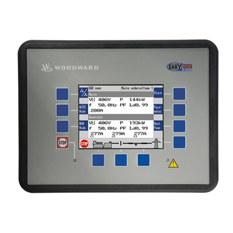
- Page 10 Series - Genset Control Chapter 4. Housing The controls of the easYgen-3000 Series are available with two different housings. Refer to the applicable section for detailed information about installation and technical data of the respective housing type. Plastic housing for front panel flush mounting with graphical LC display (easYgen-3200) Figure 4-1: easYgen-3200 - plastic housing ...
- Page 11 Manual 37468 easYgen-3000 Series - Genset Control Plastic Housing ≡≡≡≡≡≡≡≡≡≡≡≡≡≡≡≡≡≡≡≡≡≡≡≡≡ Panel Cutout h' h H Figure 4-3: Plastic housing - panel-board cutout Measure Description Tolerance Height Total 217 mm Panel cutout 183 mm + 1.0 mm Housing dimension 181 mm...
- Page 12 Manual 37468 easYgen-3000 Series - Genset Control Dimensions 217 mm 181 mm 282 mm 247 mm 87 mm 99 mm Figure 4-4: Plastic housing easYgen-3200 - dimensions Page 12/67 © Woodward...
- Page 13 Manual 37468 easYgen-3000 Series - Genset Control Clamp Fastener Installation For installation into a door panel with the fastening clamps, proceed as follows: Panel cutout cut-out Cut out the panel according to the dimensions in Table 4-1. 138,0 Note: Don't drill the holes if you want to use the clamp fasteners. If the holes are...
- Page 14 Manual 37468 easYgen-3000 Series - Genset Control Screw Kit Installation NOTE Don't drill the holes if you want to use the clamp fasteners. If the holes are drilled into the panel, the clamp fasteners cannot be used anymore! NOTE The housing is equipped with 12 nut inserts (refer to Figure 4-5 for their position), which must all be tightened properly to achieve the required degree of protection.
- Page 15 Manual 37468 easYgen-3000 Series - Genset Control Sheet Metal Housing ≡≡≡≡≡≡≡≡≡≡≡≡≡≡≡≡≡≡≡≡≡≡≡≡≡ Dimensions 227 mm 84 mm 250 mm Figure 4-6: Sheet metal housing easYgen-3100 - dimensions © Woodward Page 15/67...
- Page 16 Manual 37468 easYgen-3000 Series - Genset Control Installation The unit is to be mounted to the switch cabinet back using four screws with a maximum diameter of 6 mm. Drill the holes according to the dimensions in Figure 4-7 (dimensions shown in mm).
- Page 17 Manual 37468 easYgen-3000 Series - Genset Control Terminal Arrangement ≡≡≡≡≡≡≡≡≡≡≡≡≡≡≡≡≡≡≡≡≡≡≡≡≡ 6059585756555453525150494847464544434241 Discrete Inputs Relay Outputs Generator CT Analog Inputs Analog Outputs Mains PT Generator PT Busbar PT 0 to 500 Ohm +/-10 Vdc 0/4 to 20 mA +/- 20 mA...
- Page 18 Manual 37468 easYgen-3000 Series - Genset Control Chapter 5. Wiring Diagrams [refer to next page for wiring diagram] Figure 5-1: Wiring diagram – overview NOTE The Protective Earth terminal 61 is not connected on the easYgen-3100 with sheet metal housing. The protective earth connection at the sheet metal housing must be used instead (refer to Figure 4-9 on page 17).
- Page 19 Manual 37468 easYgen-3000 Series - Genset Control © Woodward Page 19/67...
- Page 20 Manual 37468 easYgen-3000 Series - Genset Control Chapter 6. Connections WARNING All technical data and ratings indicated in this chapter are not definite! Only the values indicated in Chapter 7: Technical Data on page 58 are valid! The following chart may be used to convert square millimeters [mm²] to AWG and vice versa: mm²...
- Page 21 Manual 37468 easYgen-3000 Series - Genset Control Power Supply ≡≡≡≡≡≡≡≡≡≡≡≡≡≡≡≡≡≡≡≡≡≡≡≡≡ WARNING – Protective Earth Protective Earth (PE) must be connected to the unit to avoid the risk of electric shock. The conductor providing the connection must have a wire larger than or equal to 2.5 mm² (14 AWG). The connection must be performed properly.
- Page 22 Manual 37468 easYgen-3000 Series - Genset Control NOTE Woodward recommends to use one of the following slow-acting protective devices in the supply line to terminal 63: • Fuse NEOZED D01 6A or equivalent • Miniature Circuit Breaker 6A / Type C (for example: ABB type: S271C6 or equivalent) Charging Alternator ≡≡≡≡≡≡≡≡≡≡≡≡≡≡≡≡≡≡≡≡≡≡≡≡≡...
- Page 23 DO NOT use both sets of voltage measuring inputs. The control unit will not measure voltage correctly if the 100 V and 400 V inputs are utilized simultaneously. NOTE Woodward recommends protecting the voltage measuring inputs with slow-acting fuses rated for 2 to 6 A. Voltage Measuring: Generator...
- Page 24 Manual 37468 easYgen-3000 Series - Genset Control Voltage Measuring: Generator, Parameter Setting '3Ph 4W OD' (3-phase, 4-wire, Open delta) Figure 6-5: Voltage measuring - generator windings, 3Ph 4W OD [4] [1] [4] [1] [4] [1] [4] Voltage 3Ph 4W OD...
- Page 25 Manual 37468 easYgen-3000 Series - Genset Control Voltage Measuring: Generator, Parameter Setting '3Ph 4W' (3-phase, 4-wire) Figure 6-7: Voltage measuring - generator windings, 3Ph 4W [4] [1] [4] [1] [4] [1] [4] Voltage 3Ph 4W Figure 6-8: Voltage measuring - generator measuring inputs, 3Ph 4W...
- Page 26 Manual 37468 easYgen-3000 Series - Genset Control Voltage Measuring: Generator, Parameter Setting '3Ph 3W' (3-phase, 3-wire) Figure 6-9: Voltage measuring - generator windings, 3Ph 3W [4] [1] [4] [1] [4] [1] [4] Voltage 3Ph 3W Figure 6-10: Voltage measuring - generator measuring inputs, 3Ph 3W...
- Page 27 Manual 37468 easYgen-3000 Series - Genset Control Voltage Measuring: Generator, Parameter Setting '1Ph 3W' (1-phase, 3-wire) Figure 6-11: Voltage measuring - generator windings, 1Ph 3W [4] [1] [4] [1] [4] [1] [4] Voltage 1Ph 3W Figure 6-12: Voltage measuring - generator measuring inputs, 1Ph 3W...
- Page 28 Manual 37468 easYgen-3000 Series - Genset Control Voltage Measuring: Generator, Parameter Setting '1Ph 2W' (1-phase, 2-wire) NOTE The 1-phase, 2-wire measurement may be performed phase-neutral or phase-phase. Please note to configure and wire the easYgen consistently. Refer to the Configuration Manual 37469 for more infor- mation.
- Page 29 Manual 37468 easYgen-3000 Series - Genset Control '1Ph 2W' Phase-Phase Measuring Figure 6-15: Voltage measuring - generator windings, 1Ph 2W (phase-phase) [4] [1] [4] [1] [4] [1] [4] Voltage 1Ph 2W Figure 6-16: Voltage measuring - generator measuring inputs, 1Ph 2W (phase-phase)
- Page 30 Manual 37468 easYgen-3000 Series - Genset Control Voltage Measuring: Mains 100 Vac 100 Vac L1 / Va 400 Vac 400 Vac 100 Vac 100 Vac L2 / Vb 400 Vac 400 Vac 100 Vac 100 Vac L3 / Vc 400 Vac...
- Page 31 Manual 37468 easYgen-3000 Series - Genset Control Voltage Measuring: Mains, Parameter Setting '3Ph 4W' (3-phase, 4-wire) Figure 6-18: Voltage measuring - mains PT windings, 3Ph 4W [4] [1] [4] [1] [4] [1] [4] Mains voltage 3Ph 4W Figure 6-19: Voltage measuring - mains measuring inputs, 3Ph 4W...
- Page 32 Manual 37468 easYgen-3000 Series - Genset Control Voltage Measuring: Mains, Parameter Setting '3Ph 3W' (3-phase, 3-wire) Figure 6-20: Voltage measuring - mains PT windings, 3Ph 3W [4] [1] [4] [1] [4] [1] [4] Mains voltage 3Ph 3W Figure 6-21: Voltage measuring - mains measuring inputs, 3Ph 3W...
- Page 33 Manual 37468 easYgen-3000 Series - Genset Control Voltage Measuring: Mains, Parameter Setting '1Ph 3W' (1-phase, 3-wire) Figure 6-22: Voltage measuring - mains PT windings, 1Ph 3W [4] [1] [4] [1] [4] [1] [4] Mains voltage 1Ph 3W Figure 6-23: Voltage measuring - mains measuring inputs, 1Ph 3W...
- Page 34 Manual 37468 easYgen-3000 Series - Genset Control Voltage Measuring: Mains, Parameter Setting '1Ph 2W' (1-phase, 2-wire) NOTE The 1-phase, 2-wire measurement may be performed phase-neutral or phase-phase. Please note to configure and wire the easYgen consistently. Refer to the Configuration Manual 37469 for more infor- mation.
- Page 35 Manual 37468 easYgen-3000 Series - Genset Control '1Ph 2W' Phase-Phase Measuring Figure 6-26: Voltage measuring - mains PT windings, 1Ph 2W (phase-phase) [4] [1] [4] [1] [4] [1] [4] Mains voltage 1Ph 2W Figure 6-27: Voltage measuring - mains measuring inputs, 1Ph 2W (phase-phase)
- Page 36 Manual 37468 easYgen-3000 Series - Genset Control Voltage Measuring: Busbar (System 1) 1Ph 2W 100 Vac 100 Vac 400 Vac 400 Vac 100 Vac 100 Vac 400 Vac 400 Vac Figure 6-28: Voltage measuring - busbar (system 1) 1Ph 2W (phase-phase)
- Page 37 Manual 37468 easYgen-3000 Series - Genset Control Voltage Measuring: Busbar (System 1), Parameter Setting '1Ph 2W' (1-phase, 2-wire) NOTE The 1-phase, 2-wire measurement may be performed phase-neutral or phase-phase. Please note to configure and wire the easYgen consistently. Refer to the Configuration Manual 37469 for more infor- mation.
- Page 38 Manual 37468 easYgen-3000 Series - Genset Control '1Ph 2W' Phase-Phase Measuring Figure 6-31: Voltage measuring - busbar PT windings, 1Ph 2W (phase-phase) [4] [1] [4] Busbar voltage 1Ph 2W Figure 6-32: Voltage measuring - busbar measuring inputs, 1Ph 2W (phase-phase)
- Page 39 Manual 37468 easYgen-3000 Series - Genset Control Current Measuring ≡≡≡≡≡≡≡≡≡≡≡≡≡≡≡≡≡≡≡≡≡≡≡≡≡ CAUTION Before disconnecting the device, ensure that the current transformer/CT is short-circuited. Generator Current NOTE Generally, one line of the current transformers secondary is to be grounded close to the CT.
- Page 40 Manual 37468 easYgen-3000 Series - Genset Control Current Measuring: Generator, Parameter Setting 'L1 L2 Gen L1 Gen L2 Gen L3 Figure 6-34: Current measuring - generator, L1 L2 L3 L1 L2 L3 Wiring terminals Notes easYgen terminal Phase s2 (k) L1...
- Page 41 Manual 37468 easYgen-3000 Series - Genset Control Mains Current 1-Phase NOTE Generally, one line of the current transformers secondary is to be grounded close to the CT. Detail: Connection of the transducers ../{x} A {x} = 1 or 5 s1 (k)
- Page 42 Manual 37468 easYgen-3000 Series - Genset Control Ground Current The mains current input can be configured to measure the mains current or ground current. Depending on how Parameter 'Input mains current as' is configured will determine if this input will measure the mains current (de- fault) or the ground current.
- Page 43 Manual 37468 easYgen-3000 Series - Genset Control Power Measuring ≡≡≡≡≡≡≡≡≡≡≡≡≡≡≡≡≡≡≡≡≡≡≡≡≡ If the unit's current transformers are wired according to the diagram shown, the following values are displayed. Parameter Description Sign displayed Generator real power Genset generating kW + Positive Generator real power...
- Page 44 Manual 37468 easYgen-3000 Series - Genset Control Different power factor displays at the unit: i0.91 (inductive) c0.93 (capacitive) lg.91 (lagging) ld.93 (leading) Reactive power display at the unit: 70 kvar (positive) -60 kvar (negative) Output at the interface: + (positive)
- Page 45 Manual 37468 easYgen-3000 Series - Genset Control MPU (Pickup) ≡≡≡≡≡≡≡≡≡≡≡≡≡≡≡≡≡≡≡≡≡≡≡≡≡ Rotating shaft Sensor Pickup input Figure 6-40: MPU - principle overview Shield 24 V MPU input (pickup) < 1,0 V Figure 6-41: MPU input Terminal Description MPU input - inductive/switching 2.5 mm²...
- Page 46 Manual 37468 easYgen-3000 Series - Genset Control Discrete Inputs ≡≡≡≡≡≡≡≡≡≡≡≡≡≡≡≡≡≡≡≡≡≡≡≡≡ Discrete Inputs: Signal Polarity The discrete inputs are electrically isolated which permits the polarity of the connections to be either positive or negative. NOTE All discrete inputs must use the same polarity, either positive or negative signals, due to the common ground.
- Page 47 Manual 37468 easYgen-3000 Series - Genset Control Discrete Inputs: Negative Polarity Signal Figure 6-44: Discrete inputs - alarm/control input - negative signal Terminal Description Discrete inputs - GND (common ground) 2.5 mm² Discrete input [DI 01]; pre-assigned to 'Emergency stop' 2.5 mm²...
- Page 48 Manual 37468 easYgen-3000 Series - Genset Control Discrete Inputs: Operation Logic Discrete inputs may be configured to normally open (N.O.) or normally closed (N.C.) states. In the state N.O., no potential is present during normal operation; if an alarm is issued or control operation is performed, the input is energized.
- Page 49 Manual 37468 easYgen-3000 Series - Genset Control Relay Outputs (LogicsManager) ≡≡≡≡≡≡≡≡≡≡≡≡≡≡≡≡≡≡≡≡≡≡≡≡≡ max. 250 Vac/dc Relay output external device Figure 6-46: Relay outputs Terminal Description Term. Com. Type Form A, N.O. make contact Ready for operation & Relay output [R 01] 2.5 mm²...
- Page 50 Manual 37468 easYgen-3000 Series - Genset Control Analog Inputs (FlexIn) ≡≡≡≡≡≡≡≡≡≡≡≡≡≡≡≡≡≡≡≡≡≡≡≡≡ It is recommended to use two-pole analog senders. This ensures an accuracy of ≤ 1% for 0 to 500 Ohm inputs and ≤ 1.2% for 0 to 20 mA inputs.
- Page 51 Manual 37468 easYgen-3000 Series - Genset Control Wiring Single-Pole Senders An accuracy of ≤ 2.5% may be achieved when using single-pole senders. The specified accuracy of ≤ 2.5% for single-pole sensors can only be achieved if the differential voltage between the genset chassis ground and PE does not exceed +/- 2.5V.
- Page 52 Manual 37468 easYgen-3000 Series - Genset Control Wiring Single and Two-Pole Senders Simultaneously An accuracy of ≤ 2.5% may be achieved when using single-pole senders. It is possible to combine single- and ≤ two-pole senders. The specified accuracy of 2.5% for single-pole sensors can only be achieved if the differen- tial voltage between the genset chassis ground and PE does not exceed +/- 2.5V.
- Page 53 Manual 37468 easYgen-3000 Series - Genset Control Analog Outputs ≡≡≡≡≡≡≡≡≡≡≡≡≡≡≡≡≡≡≡≡≡≡≡≡≡ Controller configuration and an external jumper can change the multifunction controller bias output signals. The analog outputs are galvanically isolated. Controller Wiring Speed / power controller Speed / power controller...
- Page 54 Manual 37468 easYgen-3000 Series - Genset Control Interfaces ≡≡≡≡≡≡≡≡≡≡≡≡≡≡≡≡≡≡≡≡≡≡≡≡≡ RS-485 Serial Interfaces RS-485 Serial Interface #1 (Serial Interface #2, Interface #2) Figure 6-51: RS-485 interface #1 - overview Terminal Description not connected B (TxD+) not connected B' (RxD+) not connected...
- Page 55 Manual 37468 easYgen-3000 Series - Genset Control RS-232 Serial Interface (Serial Interface #1, Interface #1) Figure 6-54: RS-232 interface - overview Terminal Description not connected RxD (receive data) TxD (transmit data) not connected GND (system ground) not connected RTS (request to send)
- Page 56 • The configured baud rate is too high for wiring length • The CAN bus cable is routed in close proximity with power cables Woodward recommends the use of shielded, twisted-pair cables for the CAN bus (i.e.: Lappkabel Unitronic LIYCY (TP) 2×2×0.25, UNITRONIC-Bus LD 2×2×0.22).
- Page 57 Manual 37468 easYgen-3000 Series - Genset Control Bus Shielding All bus connections of the easYgen are internally grounded via an RC element. Therefore, they may either be grounded directly (recommended) or also via an RC element on the opposite bus connection.
- Page 58 Manual 37468 easYgen-3000 Series - Genset Control Chapter 7. Technical Data Nameplate ------------------------------------------------------------------------------------------------------ Serial number (numerical) Date of production (YYMM) Serial number (Barcode) Item number Item revision number Details Technical data Type Description (long) Type Description (short) Approval Approvals Measuring values, voltages ------------------------------------------------------------------------------ /∆...
- Page 59 Manual 37468 easYgen-3000 Series - Genset Control Ambient variables --------------------------------------------------------------------------------------------- Power supply ................12/24 Vdc (8 to 40.0 Vdc) Intrinsic consumption ..................max. 17 W Degree of pollution ......................2 Maximum elevation ..................2,000 m ASL Insulation voltage (continuously) ................40 Vdc Insulation test voltage (1s) ..................
- Page 60 Manual 37468 easYgen-3000 Series - Genset Control Interface -------------------------------------------------------------------------------------------------------- RS-232 interface ..................... isolated Insulation voltage (continuously) ................100 Vac Insulation test voltage (1s) ..................500 Vac Version ....................... RS-232 Standard RS-485 interface ..................... isolated Insulation voltage (continuously) ................100 Vac Insulation test voltage (1s) ..................
- Page 61 Manual 37468 easYgen-3000 Series - Genset Control Chapter 8. Environmental Data Vibration--------------------------------------------------------------------------------------------------------- Frequency Range – Sine Sweep ..............5Hz to 100Hz Acceleration ......................4G Frequency Range - Random ................. 10Hz to 500Hz Power Intensity ................... 0.015G²/Hz RMS Value ....................1.04 Grms Standards ..........................
- Page 62 Manual 37468 easYgen-3000 Series - Genset Control Chapter 9. Accuracy Measuring value Display Accuracy Measuring start Notes Frequency Generator 15.0 to 85.0 Hz 5 % (of PT secondary (of 85 Hz) voltage setting) Mains 40.0 to 85.0 Hz Voltage 1.5 % (of PT second-...
- Page 63 Manual 37468 easYgen-3000 Series - Genset Control Reference conditions (for measuring the accuracy): • Input voltage ......sinusoidal rated voltage • Input current ......sinusoidal rated current • Frequency ......... rated frequency +/- 2 % • Power supply ......rated voltage +/- 2 % •...
- Page 64 Manual 37468 easYgen-3000 Series - Genset Control Appendix A. Useful Information Suitable D-SUB Connector Housings ≡≡≡≡≡≡≡≡≡≡≡≡≡≡≡≡≡≡≡≡≡≡≡≡≡ Some housings for D-Sub connectors are too wide to plug them into the unit properly. If your serial or CAN bus cable is equipped with a housing, which does not fit into the easYgen socket, you may replace the housing with...
- Page 65 Manual 37468 easYgen-3000 Series - Genset Control RJ45/8P8C Connector male / plug female / socket Figure 9-2: CAN bus pin assignment - RJ45/8P8C connector Terminal Signal Description CAN_H CAN bus line (dominant high) CAN_L CAN bus line (dominant low) CAN_GND...
- Page 66 Manual 37468 easYgen-3000 Series - Genset Control Connecting 24 V Relays ≡≡≡≡≡≡≡≡≡≡≡≡≡≡≡≡≡≡≡≡≡≡≡≡≡ Interferences in the interaction of all components may affect the function of electronic devices. One interference factor is disabling inductive loads, like coils of electromagnetic switching devices. When disabl- ing such a device, high switch-off induces voltages may occur, which might destroy adjacent electronic devices or result interference voltage pulses, which lead to functional faults, by capacitive coupling mechanisms.
- Page 67 Phone +49 (0) 711 789 54-0 • Fax +49 (0) 711 789 54-100 stgt-info@woodward.com Homepage http://www.woodward.com/power Woodward has company-owned plants, subsidiaries, and branches, as well as authorized distributors and other authorized service and sales facilities throughout the world. Complete address/phone/fax/e-mail information for all locations is available on our website (www.woodward.com).
Need help?
Do you have a question about the easYgen-3000 Series and is the answer not in the manual?
Questions and answers