
Related Manuals for Woodward easYgen-300


Summary of Contents for Woodward easYgen-300
- Page 1 37218D easYgen-300 Genset Control Operation Manual Software Version starting from 2.0008 Manual 37218D...
- Page 2 Provides other helpful information that does not fall under the warning or caution categories. Woodward reserves the right to update any portion of this publication at any time. Information provided by Woodward is believed to be correct and reliable. However, Woodward assumes no responsibility unless otherwise expressly undertaken.
-
Page 3: Table Of Contents
Manual 37218D easYgen-300 Series - Genset Control Revision History Rev. Date Editor Change NEW 04-10-15 Release 05-12-14 Minor corrections; MCB closing limit description added; update to reflect version V2.0006 06-03-23 Minor corrections; wire size conversion chart added; update to reflect version V2.0007 (refer to Update In-... - Page 4 Manual 37218D easYgen-300 Series - Genset Control 7. O ................34 HAPTER PERATION AND AVIGATION Operation and Display ........................... 35 Purpose of the Status LEDs ......................35 Operating the easYgen ....................... 35 Acknowledging Alarm Messages ....................35 ...
- Page 5 Manual 37218D easYgen-300 Series - Genset Control Monitoring .............................. 76 Monitoring: Generator ........................76 Monitoring: Generator Overfrequency ..................76 Monitoring: Generator Underfrequency ..................77 Monitoring: Generator Overvoltage ..................... 78 Monitoring: Generator Undervoltage ................... 79 ...
- Page 6 Manual 37218D easYgen-300 Series - Genset Control F. S ..................... 120 PPENDIX ERVICE PTIONS Product Service Options ........................120 Returning Equipment For Repair ......................120 Packing a Control ........................121 Return Authorization Number RAN ................... 121 ...
- Page 7 Figure 5-3: Wiring diagram - easYgen350..........................18 Figure 5-4: Wiring diagram - easYgen350X ..........................19 Figure 6-1: easYgen-300 back view - terminal arrangement ....................20 Figure 6-2: Power supply ................................21 Figure 6-3: Charging alternator input/output ..........................21 ...
- Page 8 Manual 37218D easYgen-300 Series - Genset Control Tables Table 1-1: Manual - overview ..............................9 Table 2-1: easYgen series 300 product features........................12 Table 4-1: Housing - panel cut-out ............................14 Table 6-1: Power supply - terminal assignment ........................21 ...
-
Page 9: Chapter 1. General Information
Manual 37218D easYgen-300 Series - Genset Control Chapter 1. General Information Related Documents ≡≡≡≡≡≡≡≡≡≡≡≡≡≡≡≡≡≡≡≡≡≡≡≡≡ Type English German easYgen-300 Series easYgen-300 – Manual this manual 37218 Additional Manuals LeoPC1 – User Manual 37146 GR37146 PC program for configuration, parameter visualization, remote control, data logging, language upload, alarm and user management, and event recorder management. -
Page 10: Overview
Manual 37218D easYgen-300 Series - Genset Control Overview ≡≡≡≡≡≡≡≡≡≡≡≡≡≡≡≡≡≡≡≡≡≡≡≡≡ Figure 1-2: Functional overview Page 10/125 © Woodward... - Page 11 Manual 37218D easYgen-300 Series - Genset Control The easYgen-300 Series generator set controller provides the following functions: • Genset control • Engine and generator protection • Engine data measurement - including oil pressure and temperature, coolant temperature, battery voltage, speed, service hours, etc.
-
Page 12: Easygen Series 300 Overview
Table 2-1: easYgen series 300 product features NOTE Some parameters of the easYgen-300 series can only be configured using the Direct Configuration Ca- ble DPC (P/N 5417-557) and a notebook/PC with the software LeoPC1. These parameters are indicated with an in the parameter description under Parameters starting from page 70 and can not be confi- gured at the unit directly. -
Page 13: Chapter 3. Electrostatic Discharge Awareness
CAUTION To prevent damage to electronic components caused by improper handling, read and observe the pre- cautions in Woodward manual 82715, Guide for Handling and Protection of Electronic Controls, Printed Circuit Boards, and Modules. NOTE The unit is capable to withstand an electrostatic powder coating process with a voltage of up to 85 kV and a current of up to 40 µA. -
Page 14: Chapter 4. Housing
Manual 37218D easYgen-300 Series - Genset Control Chapter 4. Housing Dimensions / Panel Cut-Out ≡≡≡≡≡≡≡≡≡≡≡≡≡≡≡≡≡≡≡≡≡≡≡≡≡ Figure 4-1: Housing - panel cut-out Description Dimension Tolerance Height Total 158 mm Panel cut-out 138 mm + 1.0 mm Housing dimension 136 mm Width... -
Page 15: Installation
Manual 37218D easYgen-300 Series - Genset Control Installation ≡≡≡≡≡≡≡≡≡≡≡≡≡≡≡≡≡≡≡≡≡≡≡≡≡ For installation into a door panel, proceed as follows: Panel cut-out Cut out the panel according to the dimensions in Figure 4-1. Remove terminals Loosen the wire connection terminal screws on the back of the unit and remove the wire connection terminal strips if required (1). -
Page 16: Chapter 5. Wiring Diagrams
Free programmable (relay 4) Fuel relay (relay 5) Crank (relay 6) Engine D+, 24 Vdc (charge alternator) D+, 12 Vdc (charge alternator) Subject to technical mocifications. 2004-09-21 | easYgen-300 Wiring Diagram eYg300ww-0439-ap.skf Figure 5-1: Wiring diagram - easYgen-320 Page 16/125 © Woodward... -
Page 17: Figure 5-2: Wiring Diagram - Easygen320X
Crank (relay 6) Engine D+, 24 Vdc (charge alternator) D+, 12 Vdc (charge alternator) MPU + MPU - CAN-L CAN-H Subject to technical mocifications. 2004-09-21 | easYgen-300 Wiring Diagram eYg300ww-0439-ap.skf Figure 5-2: Wiring diagram - easYgen320X © Woodward Page 17/125... -
Page 18: Figure 5-3: Wiring Diagram - Easygen350
Free programmable (relay 4) Fuel relay (relay 5) Crank (relay 6) Engine D+, 24 Vdc (charge alternator) D+, 12 Vdc (charge alternator) Subject to technical mocifications. 2004-09-21 | easYgen-300 Wiring Diagram eYg300ww-0439-ap.skf Figure 5-3: Wiring diagram - easYgen350 Page 18/125 © Woodward... -
Page 19: Figure 5-4: Wiring Diagram - Easygen350X
Crank (relay 6) Engine D+, 24 Vdc (charge alternator) D+, 12 Vdc (charge alternator) MPU + MPU - CAN-L CAN-H Subject to technical mocifications. 2004-09-21 | easYgen-300 Wiring Diagram eYg300ww-0439-ap.skf Figure 5-4: Wiring diagram - easYgen350X © Woodward Page 19/125... -
Page 20: Chapter 6. Connections
Chart: Wire Size on page 105 to convert the sizes to AWG. Terminal Arrangement ≡≡≡≡≡≡≡≡≡≡≡≡≡≡≡≡≡≡≡≡≡≡≡≡≡ 20 19 upper terminal strip configuration plug only [320X], [350X] lower terminal strip 21 22 35 36 Figure 6-1: easYgen-300 back view - terminal arrangement Page 20/125 © Woodward... -
Page 21: Power Supply
The control unit is capable of handling voltage drops to 0 V for a maximum of 10 ms. CAUTION Ensure that the engine will be shut down by an external device in case the power supply of the easYgen-300 control unit fails. Failure to do so may result in damages to the equipment. Charging Alternator ≡≡≡≡≡≡≡≡≡≡≡≡≡≡≡≡≡≡≡≡≡≡≡≡≡... -
Page 22: Voltage Measuring
Figure 6-4 to Figure 6-12. NOTE Please note that not all measuring methods can be performed with all models of the easYgen-300 se- ries. The methods of measurement are indicated in the wiring diagrams for the respective models. -
Page 23: Voltage Measuring: Generator
Manual 37218D easYgen-300 Series - Genset Control Voltage Measuring: Generator Voltage Measuring: Generator 3Ph 4W, [320X], [350X] Generator voltage 3Ph 4W easYgen 320X & 350X Figure 6-4: Voltage measuring - generator 3Ph 4W Voltage Measuring: Generator 3Ph 3W, [320X], [350X] Generator voltage 3Ph 3W easYgen 320X &... -
Page 24: Figure 6-7: Voltage Measuring - Generator 1Ph 2W, Phase-Neutral
Manual 37218D easYgen-300 Series - Genset Control Voltage Measuring: Generator 1Ph 2W, [320], [320X], [350], [350X] Phase-Neutral Voltage Measuring Generator voltage 1Ph 2W Generator voltage 1Ph 2W easYgen 320 & 350 easYgen 320X & 350X Figure 6-7: Voltage measuring - generator 1Ph 2W, phase-neutral Phase-Phase Voltage Measuring It is also possible to perform a phase-phase voltage measuring. -
Page 25: Voltage Measuring: Mains, [350], [350X]
Manual 37218D easYgen-300 Series - Genset Control Voltage Measuring: Mains, [350], [350X] Voltage Measuring: Mains 3Ph 4W Mains voltage 3Ph 4W easYgen 350 & 350X Figure 6-9: Voltage measuring - mains 3Ph 4W Voltage Measuring: Mains 3Ph 3W, [350X] Mains voltage 3Ph 3W... -
Page 26: Figure 6-12: Voltage Measuring - Mains 1Ph 2W
Manual 37218D easYgen-300 Series - Genset Control Voltage Measuring: Mains 1Ph 2W, [350X] Mains voltage 1Ph 2W easYgen 350X Figure 6-12: Voltage measuring - mains 1Ph 2W Terminal Description Mains voltage - phase L3 480 Vac 2.5 mm² Mains voltage - phase L2 480 Vac 2.5 mm²... -
Page 27: Mpu (Pickup) [320X]
Manual 37218D easYgen-300 Series - Genset Control MPU (pickup) [320X], [350X] ≡≡≡≡≡≡≡≡≡≡≡≡≡≡≡≡≡≡≡≡≡≡≡≡≡ Rotating shaft Sensor Pickup input Figure 6-13: MPU - principle overview Shield 24 V Pickup input < 1,0 V Figure 6-14: MPU input Terminal Description inductive/switching 2.5 mm²... -
Page 28: Discrete Inputs
Manual 37218D easYgen-300 Series - Genset Control Discrete Inputs ≡≡≡≡≡≡≡≡≡≡≡≡≡≡≡≡≡≡≡≡≡≡≡≡≡ Discrete Inputs: Bipolar Signals The discrete inputs are galvanically isolated allowing for a bipolar connection. The discrete inputs are able to handle positive or negative signals. NOTE All discrete inputs must use the same polarity, either positive or negative signals, due to the common ground. -
Page 29: Discrete Inputs: Operation Logic
Figure 6-18: Discrete inputs - alarm/control inputs - operation logic For the easYgen-300 series, the discrete inputs 1-3 are configured to a factory default and cannot be changed. The discrete inputs 4 and 5 are freely configurable depending on the parameter "Ignore CB reply". If this para- meter is set to "YES", the discrete inputs are freely configurable, and the operation logic may be configured ei-... -
Page 30: Relay Outputs
Manual 37218D easYgen-300 Series - Genset Control Relay Outputs ≡≡≡≡≡≡≡≡≡≡≡≡≡≡≡≡≡≡≡≡≡≡≡≡≡ The easYgen series 300 provides up to six (6) galvanically isolated relay outputs. Some relay outputs have fixed assignments and cannot be configured. max. 250 Vac/dc Relay output external device... -
Page 31: Interfaces
39/40 Table 6-10: Interfaces - connection overview NOTE The DPC cable (P/N 5417-557) is intended for service operation only. Do not operate the easYgen-300 with the DPC plugged into the unit during regular operation. NOTE The CAN interface is only used for the visualization of J1939 data from the ECU. -
Page 32: Can Bus [320X], [350X]
• Incorrect baud rate (too high) for length of CAN bus • The CAN bus cable is co-routed with power cables Woodward recommends the use of twisted-pair cables for the CAN bus (i.e.: Lappkabel Unitronic LIYCY (TP) 2×2×0.25, UNITRONIC-Bus LD 2×2×0.22). -
Page 33: Dpc - Direct Configuration Cable
Manual 37218D easYgen-300 Series - Genset Control Maximum CAN bus Length The maximum length of the communication bus wiring is dependent on the configured Baud rate. Refer to Table 6-11 for the maximum bus length (Source: CANopen; Holger Zeltwanger (Hrsg.); 2001 VDE VERLAG GMBH, Berlin und Offenbach;... -
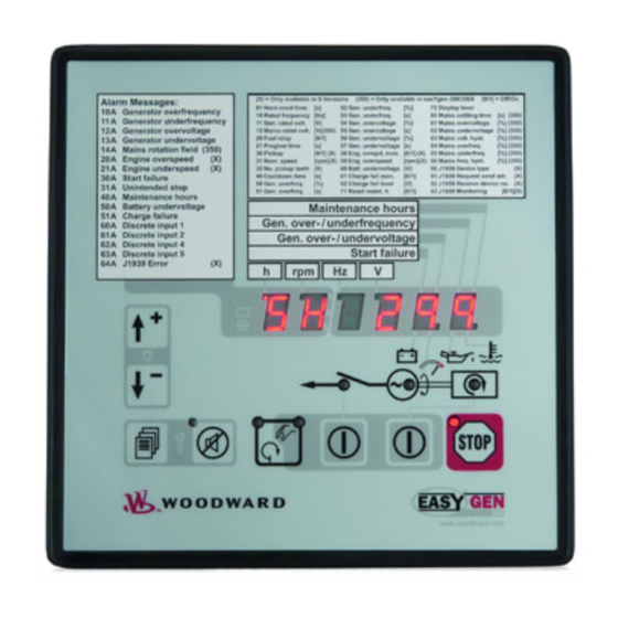
Page 34: Chapter 7. Operation And Navigation
Manual 37218D easYgen-300 Series - Genset Control Chapter 7. Operation and Navigation Figure 7-1: Front panel and display Figure 7-1 illustrates the front panel/display which includes push-buttons, LEDs and the alphanumerical 7 seg- ment LED display. A short description of the front panel is given below. -
Page 35: Operation And Display
Manual 37218D easYgen-300 Series - Genset Control Operation and Display ≡≡≡≡≡≡≡≡≡≡≡≡≡≡≡≡≡≡≡≡≡≡≡≡≡ Purpose of the Status LEDs The easYgen has several status LEDs to indicate the operating state. The LEDs indicate the following conditions: (on): Mains voltage present (only easYgen-350 and 350X) -
Page 36: Configuring The Easygen
Display of the Operating Values The easYgen-300 control units are able to display various measured values during operation depending on the re- spective easYgen model. You may advance through the single value displays using the Scroll button... -
Page 37: Default Operating Value Display
Manual 37218D easYgen-300 Series - Genset Control Default Operating Value Display The easYgen detects and selects the default operating value display by evaluating the measured voltage and the circuit breaker position. This default operating value is always displayed first. The operator may advance through... - Page 38 Manual 37218D easYgen-300 Series - Genset Control Parameter / display level Display Applies to Generator voltage easYgen-350X (phase-neutral) easYgen-350 easYgen-320X DL 2 easYgen-320 Generator voltage easYgen-350X Average of the phase voltages easYgen-350 (one of the three phase indica- easYgen-320X tors is displayed alternately)
-
Page 39: Table 7-2: Display Of Operating Values
Manual 37218D easYgen-300 Series - Genset Control Parameter / display level Display Applies to Engine speed easYgen-350X (display is not shown if the easYgen-350 MPU is disabled) easYgen-320X DL 1 easYgen-320 Operating hours counter easYgen-350X (display is six-digit with one... -
Page 40: J1939 Visualization [320X], [350X]
J1939 Operating Value Display The easYgen-300 with the X package is able to display standard J1939 messages, which are sent by the engine control to the easYgen via the CAN bus. The values are displayed on the unit and in LeoPC1. In order to visual- ize J1939 messages with LeoPC1, the PC/laptop running LeoPC1 must be connected via the DPC interface (refer to page 32). -
Page 41: Figure 7-3: J1939 Fault Display
DL 1 65270 Table 7-3: J 1939 messages In case of a defective sensor or a broken wire the easYgen-300 displays four dashes instead of the J1939 value following the respective J1939 identifier. Figure 7-3: J1939 fault display The above display shows that the engine oil pressure (identifier 9r) sensor is defective or the cable from the sen- sor to the ECU is unplugged or broken. -
Page 42: Table 7-4: Dm1/Dm2 Error Message Composition
J1939 DM1/DM2 Error Message Display The easYgen-300 with the X package is able to display J1939 DM1 and DM2 error messages, which are sent by the engine control to the easYgen via the CAN bus. The J1939 visualization can be configured with parame- ter 90, J1939 device type. -
Page 43: Alarm Messages
Manual 37218D easYgen-300 Series - Genset Control Alarm Messages If the easYgen detects a fault condition, LED starts to flash. The alarm message is displayed in the seven- segment display with a blinking "A" for alarm, an alarm number, and the respective alarm segment, if appli- cable. - Page 44 Manual 37218D easYgen-300 Series - Genset Control Alarm Alarm class Display Applies to 14 Mains rotation B: Alarm 350X field mismatch 320X 20 Engine overspeed F: Shutdown 350X 320X 21 Engine underspeed F: Shutdown 350X 320X 30 Start fail F: Shutdown...
-
Page 45: Configuration Displays
Manual 37218D easYgen-300 Series - Genset Control Alarm Alarm class Display Applies to 65 J1939 DM1 amber Selectable 350X warning lamp B or F 320X 66 J1939 DM1 red Selectable 350X stop lamp B or F 320X Table 7-6: Alarm messages NOTE Discrete Inputs 4 &... - Page 46 Manual 37218D easYgen-300 Series - Genset Control Parameter Range Display Applies to Nominal speed 500 to 4000 rpm 350X [1 rpm interval] 320X Number of 2 to 260 teeth 350X teeth [1 tooth interval] 320X Cooldown time 0 to 999 s...
- Page 47 Manual 37218D easYgen-300 Series - Genset Control Parameter Range Display Applies to Battery under- 8.0 to 42.0 V 350X voltage thre- [0.1 V interval] shold 320X Battery charge 0 = off, 1 = on 350X failure monitor- ing on/off 320X...
-
Page 48: Display Hierarchy
Manual 37218D easYgen-300 Series - Genset Control Parameter Range Display Applies to Mains phase 0 = Off 350X rotation moni- 1 = On toring - self 320X acknowledge J1939 Device 0 = Off 350X Type 1 = Standard 2 = Scania S6... -
Page 49: Chapter 8. Functional Description
Manual 37218D easYgen-300 Series - Genset Control Chapter 8. Functional Description Overview ≡≡≡≡≡≡≡≡≡≡≡≡≡≡≡≡≡≡≡≡≡≡≡≡≡ Application mode {1 breaker open/close} {2 breakers open/close } easYgen Version [320], [320X], [350], [350X] [350], [350X] Operation Mode AUTO AUTO Operate the engine • Start engine by:... -
Page 50: Application Modes
Manual 37218D easYgen-300 Series - Genset Control Application Modes ≡≡≡≡≡≡≡≡≡≡≡≡≡≡≡≡≡≡≡≡≡≡≡≡≡ The most important features of the application modes are illustrated in the following. Please note that the 2 breaker application mode is only possible with the easYgen versions [350], and [350X]. -
Page 51: Operating Modes
Manual 37218D easYgen-300 Series - Genset Control Operating Modes ≡≡≡≡≡≡≡≡≡≡≡≡≡≡≡≡≡≡≡≡≡≡≡≡≡ Operating Mode STOP NOTE Selecting the operating mode STOP is not the same as an EMERGENCY STOP. In some cases the ea- sYgen will perform additional logic functions, such as an engine cool down period, before the engine is stopped. -
Page 52: Operating Mode Manual
Manual 37218D easYgen-300 Series - Genset Control Operating Mode MANUAL NOTE You find an overview about the buttons, LEDs and the seven-segment display under Operation and Na- vigation on page 34. In the MANUAL operating mode (AUTO - MANUAL button... - Page 53 Manual 37218D easYgen-300 Series - Genset Control MCB close sequence: Action Breaker control Press the BREAKER CONTROL button Operation Open GCB The GCB close relay (relay 2) de-energizes to open the GCB – LED goes out Delay Breaker delay The control unit waits for the breaker transfer time configured in the...
- Page 54 Manual 37218D easYgen-300 Series - Genset Control Engine start sequence: Action START Press the START - STOP button Delay Preglow time If diesel start logic is selected the relay will energize the glow plugs for the time configured in the engine parameters (page 73)
- Page 55 Manual 37218D easYgen-300 Series - Genset Control Application Mode {1 breaker open/close} – [320], [320X], [350], [350X] The START - STOP button Starts the engine (if the engine is stopped, LED is not illuminated) Stops the engine (if the engine is running, LED...
-
Page 56: Operating Mode Automatic
Manual 37218D easYgen-300 Series - Genset Control Operating Mode AUTOMATIC In the AUTOMATIC operating mode, all engine, GCB, and/or MCB functions are operated via the discrete inputs or automatically by the control unit (i.e. a mains failure). The function of the easY- gen depends on the configuration of the unit and how the external signals are used. - Page 57 Manual 37218D easYgen-300 Series - Genset Control Detailed operation with 2 CBs in automatic mode (mains are not present) - [350], [350X] Preconditions: • Generator is stopped – LED is not illuminated • MCB is closed – LED is illuminated •...
- Page 58 Manual 37218D easYgen-300 Series - Genset Control AMF / Auto Mains Failure Operation - [350], [350X] The operation sequence for an AMF operation is similar to the above sequence with the difference that a remote start signal is not required for the engine start and the engine monitoring delay time is not considered, i.e. the CBs are operated immediately.
- Page 59 Manual 37218D easYgen-300 Series - Genset Control Detailed operation with 1 CB in Automatic mode Preconditions: • Generator is stopped – LED is not illuminated • Unit is in Automatic mode – LED is illuminated Start sequence: Action Remote start...
-
Page 60: Breaker Closure Limits
≡≡≡≡≡≡≡≡≡≡≡≡≡≡≡≡≡≡≡≡≡≡ Generator Circuit Breaker The easYgen-300 series has fixed breaker closure limits which prevent the GCB closure if the generator voltage and/or frequency is/are not within these limits. These limits depend on the parameters rated system frequency and rated generator voltage (refer to Measuring on page 71) and cannot be changed. The limits are set as follows:... -
Page 61: Functional Description Of The Oil Pressure Input Di1
Series - Genset Control Functional Description of the Oil Pressure Input DI1 ≡≡≡≡≡≡≡≡≡≡≡≡≡≡≡≡≡≡≡≡≡≡≡≡≡≡≡≡≡≡≡≡≡≡≡≡≡≡≡≡≡≡≡≡≡≡ The easYgen-300 series is provided with an input for oil pressure. The function of this discrete input is described in the following. Vdc (GND) Discrete input DI1 (oil pressure) -
Page 62: Firing Speed Detection And Crank Termination
Manual 37218D easYgen-300 Series - Genset Control Firing Speed Detection and Crank Termination ≡≡≡≡≡≡≡≡≡≡≡≡≡≡≡≡≡≡≡≡≡≡≡≡≡≡≡≡≡≡≡≡≡≡≡≡≡≡≡≡≡≡≡≡≡ The firing speed is used for crank termination if the parameter "Crank termination by DI1" is not enabled (refer to Parameter "Crank termination by DI1" on page 61 if this parameter is enabled). When "Crank termination by DI1"... -
Page 63: Functional Description Of The Charging Alternator Input/Output
Functional Description of the Charging Alternator Input/Output ≡≡≡≡≡≡≡≡≡≡≡≡≡≡≡≡≡≡≡≡≡≡≡≡≡≡≡≡≡≡≡≡≡≡≡≡≡≡≡≡≡≡≡≡≡ The easYgen-300 series monitors the charging alternator operation with the following functionality. In some cases the alternator itself needs auxiliary excitation from an auxiliary DC source to build up its terminal voltage during start-up. For this, the battery will be connected into the alternator excitation windings during the engine start-up. -
Page 64: Functional Description Of The 2
CB Close Delay Time ≡≡≡≡≡≡≡≡≡≡≡≡≡≡≡≡≡≡≡≡≡≡≡≡≡≡≡≡≡≡≡≡≡≡≡≡≡≡≡≡≡≡≡≡≡ The easYgen-300 series provides Delayed close GCB and Delayed close MCB (only [350], [350X]) signals in the list of configurable parameters (find more details about this under Relay Outputs on page 92) in order to meet the requirements of some special circuit breaker types which require an Enable CB Close signal before the actual CB close signal. -
Page 65: Functional Description Of The Engine Released Signal
Functional Description of the Engine Released Signal ≡≡≡≡≡≡≡≡≡≡≡≡≡≡≡≡≡≡≡≡≡≡≡≡≡≡≡≡≡≡≡≡≡≡≡≡≡≡≡≡≡≡≡≡≡ The easYgen-300 series provides the engine released signal in the list of configurable parameters (find more de- tails about this under Relay Outputs on page 92). It is possible to use this signal for some special applications. Its functionality is described in the following for an emergency power supply. -
Page 66: Chapter 9. Configuration
Manual 37218D easYgen-300 Series - Genset Control Chapter 9. Configuration Restoring Default Values ≡≡≡≡≡≡≡≡≡≡≡≡≡≡≡≡≡≡≡≡≡≡≡≡≡ The easYgen can be reset to factory settings easily. This may be comfortable for configuring the easYgen from a known state. NOTE The unit has to be in Operating Mode STOP (page 51) to load the default values. -
Page 67: Configuration Using The Pc
COM1 port of your notebook/PC. • You can now start the PC program as follows: - by "Start/Program/Woodward/LeoPC1" (version 3.1 or higher) and opening the respective cfg file, or - by a double click on the respective file ending ".cfg" in the subdirectory "/LeoPC1". -
Page 68: Editing The Configuration File
Configuring the Flags ≡≡≡≡≡≡≡≡≡≡≡≡≡≡≡≡≡≡≡≡≡≡≡≡≡ The easYgen-300 series provides four configurable LED flags in the alphanumerical display to indicate alarms. One or more alarm messages can be assigned to each one of these flags (i.e. the respective flag will be illumi- nated if the configured alarm state(s) occur(s) in addition to the regular alarm indication). -
Page 69: Figure 9-2: Flag Configuration Default
Manual 37218D easYgen-300 Series - Genset Control The flag parameters are displayed in LeoPC1 (refer to Configuration Using the PC on page 67 and the LeoPC1 user manual 37146 for more information) under System – Codes like shown in Figure 9-2 in default state (alarm "Start fail"... -
Page 70: Chapter 10. Parameters
Manual 37218D easYgen-300 Series - Genset Control Chapter 10. Parameters The following description of parameters is expanded to include all parameters that are accessible through LeoPC1. Not all parameters are accessible via the front panel. Most of the parameters, which are accessible via the front panel are password protected and are only accessible after entering a password. -
Page 71: Measuring
Manual 37218D easYgen-300 Series - Genset Control Measuring ≡≡≡≡≡≡≡≡≡≡≡≡≡≡≡≡≡≡≡≡≡≡≡≡≡ Rated system frequency 50/60 Hz Rated system frequency Nennfrequenz im System The rated frequency of the system has to be configured here. [320] [320X] [350] [350X] The generator frequency monitoring as well as the mains failure limits refer to the value configured in this parameter. -
Page 72: Application
Manual 37218D easYgen-300 Series - Genset Control Application ≡≡≡≡≡≡≡≡≡≡≡≡≡≡≡≡≡≡≡≡≡≡≡≡≡ Ignore CB reply YES/NO Ignore CB reply Ignoriere Rückmeldung LS This parameter controls the function of the discrete inputs DI4 and DI5. [320] [320X] [350] [350X] YES ..... The discrete inputs DI4 and DI5 are freely configurable. The pa- rameters of the discrete inputs can be accessed and configured via LeoPC1. -
Page 73: Engine
Manual 37218D easYgen-300 Series - Genset Control Engine ≡≡≡≡≡≡≡≡≡≡≡≡≡≡≡≡≡≡≡≡≡≡≡≡≡ Engine: Diesel Fuel relay close to stop / open to stop Fuel relay: close to stop Kraftstoffmagnet: Stopmag. close to stop . To stop the engine the stop solenoid is energized. Once speed is no... -
Page 74: Engine: Start/Stop Automatic
Manual 37218D easYgen-300 Series - Genset Control Engine: Start/Stop Automatic Starter time 1 to 10 s Starter time Einrückzeit Anlasser The maximum time during which the crank relay remains enabled. The starter re- [320] [320X] [350] [350X] lay de-energizes when the engine reaches ignition speed or the configured time expires. -
Page 75: Breaker
Manual 37218D easYgen-300 Series - Genset Control Breaker ≡≡≡≡≡≡≡≡≡≡≡≡≡≡≡≡≡≡≡≡≡≡≡≡≡ Transfer time GCB/MCB 0.10 to 99.99 s Transfer time GCBMCB Pasuenzeit GLSNLS Switching from generator supply to mains supply or from mains supply to gene- [320] [320X] [350] [350X] rator supply occurs automatically depending on the operating conditions. The time between the reply "power circuit breaker is open"... -
Page 76: Monitoring
Manual 37218D easYgen-300 Series - Genset Control Monitoring ≡≡≡≡≡≡≡≡≡≡≡≡≡≡≡≡≡≡≡≡≡≡≡≡≡ Time until horn reset 0 to 1,000 s Time until horn reset Zeit bis Hupenreset The alarm LED flashes and the centralized alarm (horn) is issued when a new B [320] [320X] [350] [350X] to F class alarm is detected. -
Page 77: Monitoring: Generator Underfrequency
Manual 37218D easYgen-300 Series - Genset Control Monitoring: Generator Underfrequency Generator underfrequency monitoring fixed to ON Monitoring Überwachung The generator underfrequency monitoring is always enabled and cannot be dis- [320] [320X] [350] [350X] abled. Generator underfrequency limit 50.0 to 130.0 %... -
Page 78: Monitoring: Generator Overvoltage
Manual 37218D easYgen-300 Series - Genset Control Monitoring: Generator Overvoltage Generator overvoltage monitoring fixed to ON Monitoring Überwachung The generator overvoltage monitoring is always enabled and cannot be disabled. [320] [320X] [350] [350X] Generator overvoltage limit 50.0 to 125.0 %... -
Page 79: Monitoring: Generator Undervoltage
Manual 37218D easYgen-300 Series - Genset Control Monitoring: Generator Undervoltage Generator undervoltage monitoring fixed to ON Monitoring Überwachung The generator undervoltage monitoring is always enabled and cannot be disabled. [320] [320X] [350] [350X] Generator undervoltage limit 50.0 to 125.0 %... -
Page 80: Monitoring: Mains
Manual 37218D easYgen-300 Series - Genset Control Monitoring: Mains Mains phase rotation monitoring ON / OFF Monitoring Überwachung ON ....Phase rotation monitoring is carried out according to the following [320] [320X] [350] [350X] parameters OFF ..... Monitoring is disabled. - Page 81 Manual 37218D easYgen-300 Series - Genset Control Emergency power: low voltage threshold 50.0 to 130.0 % Low voltage threshold Untere Grenzspannung This value refers to the Rated mains voltage (see page 71). [320] [320X] [350] [350X] This value is referred to for mains failure recognition and mains estimation. If the monitored value exceeds the adjusted limit, this is recognized as a mains failure and an emergency power operation is initiated.
-
Page 82: Figure 10-1: Voltage/Frequency Hysteresis
Manual 37218D easYgen-300 Series - Genset Control Emergency power: frequency hysteresis 0.0 to 50.0 % Frequency hysteresis Frequenzhysterese This value refers to the Rated system frequency (see page 71). [320] [320X] [350] [350X] This value is referred to for mains failure recognition and mains estimation. If the monitored value exceeds the adjusted limit, this is recognized as a mains failure and an emergency power operation is initiated. -
Page 83: Monitoring: Engine Overspeed
Manual 37218D easYgen-300 Series - Genset Control Monitoring: Engine Overspeed Engine overspeed monitoring ON / OFF Monitoring Überwachung ON ....Overspeed monitoring of the engine speed is carried out according [320] [320X] [350] [350X] to the following parameters. OFF ....No monitoring is carried out. -
Page 84: Monitoring: Engine Underspeed
Manual 37218D easYgen-300 Series - Genset Control Monitoring: Engine Underspeed Engine underspeed monitoring fixed to ON Monitoring Überwachung The engine underspeed monitoring is always enabled and cannot be disabled. [320] [320X] [350] [350X] Engine underspeed limit fixed to 1,000 RPM... -
Page 85: Monitoring: Engine Start Fail
Manual 37218D easYgen-300 Series - Genset Control Monitoring: Engine Start Fail Engine start fail monitoring fixed to ON Monitoring Überwachung The engine start fail monitoring is always enabled and cannot be disabled. [320] [320X] [350] [350X] Engine number of start attempts... -
Page 86: Monitoring: Battery Undervoltage
Manual 37218D easYgen-300 Series - Genset Control Monitoring: Battery Undervoltage Battery undervoltage monitoring fixed to ON Monitoring Überwachung The battery undervoltage monitoring is always enabled and cannot be disabled. [320] [320X] [350] [350X] Battery undervoltage limit 8.0 to 42.0 V... -
Page 87: Monitoring: Battery Charge Voltage
Manual 37218D easYgen-300 Series - Genset Control Monitoring: Battery Charge Voltage Battery charge voltage monitoring ON / OFF Monitoring Überwachung ON ....Battery charge voltage monitoring is carried out according to the [320] [320X] [350] [350X] following parameters. OFF ....No monitoring is carried out. -
Page 88: Monitoring: Interface
It may be possible to configure all classes of alarms in this parameter but only alarm classes B and F are implemented in the easYgen-300 series. Ensure that only class B or F is con- figured here. -
Page 89: Monitoring: Interface: J1939 Amber Warning Lamp Dm1
It may be possible to configure all classes of alarms in this parameter but only alarm classes B and F are implemented in the easYgen-300 series. Ensure that only class B or F is configured here. -
Page 90: Monitoring: Interface: J1939 Red Stop Lamp Dm1
It may be possible to configure all classes of alarms in this parameter but only alarm classes B and F are implemented in the easYgen-300 series. Ensure that only class B or F is configured here. -
Page 91: Discrete Inputs
≡≡≡≡≡≡≡≡≡≡≡≡≡≡≡≡≡≡≡≡≡≡≡≡≡ The easYgen-300 series has 5 discrete inputs (DI1 to DI5). The discrete inputs 1 & 2 are pre-defined as alarm in- puts for oil pressure (DI1) and coolant temperature (DI2). The discrete input 3 is a control input for remote start. -
Page 92: Relay Outputs
Series - Genset Control Relay Outputs ≡≡≡≡≡≡≡≡≡≡≡≡≡≡≡≡≡≡≡≡≡≡≡≡≡ The easYgen-300 series has 6 (or 4 for [320] & [320X]) relay outputs. The relay outputs 3 and 4 can be freely configured with one signal output from the list of configurable parameters in Table 10-1 (only [350] &... -
Page 93: Table 10-1: Relay Outputs - List Of Configurable Parameters
Manual 37218D easYgen-300 Series - Genset Control Configurable Parameter Description Applies to The assigned relay will energize if … [320] [320X] [350] [350X] Generator overfrequency 1 … the generator frequency is exceeded (refer to Monitoring: Generator Overfrequency on page 76 for details) Generator underfrequency 1 …... -
Page 94: Counter
Manual 37218D easYgen-300 Series - Genset Control Counter ≡≡≡≡≡≡≡≡≡≡≡≡≡≡≡≡≡≡≡≡≡≡≡≡≡ Maintenance hours 0 to 9,999 h Maintenance hours Wartungsintervall Stunden To disable the maintenance counter "hours" configure "0". [320] [320X] [350] [350X] This parameter defines the remaining hours until the next maintenance call oc- curs. -
Page 95: Interfaces
Manual 37218D easYgen-300 Series - Genset Control Interfaces ≡≡≡≡≡≡≡≡≡≡≡≡≡≡≡≡≡≡≡≡≡≡≡≡≡ CAN Interface CAN baudrate 20/50/100/125/250/500/800/1000 kBd Baudrate Baudrate The CAN bus baudrate is configured here. [320] [320X] [350] [350X] NOTE The baud rate is the same for all devices connected to the CAN bus regardless of the selected protocol. -
Page 96: System
Manual 37218D easYgen-300 Series - Genset Control System ≡≡≡≡≡≡≡≡≡≡≡≡≡≡≡≡≡≡≡≡≡≡≡≡≡ Codes Set commissioning level code 0000 to 9999 Comissioning level code Code Inebtriebnahme Ebene The user may configure the HMI password (Parameter 00) here. The HMI pass- [320] [320X] [350] [350X] word protects the configuration of the unit via the front panel. -
Page 97: Flags
Series - Genset Control Flags The easYgen-300 series provides four configurable LED flags in the alphanumerical display to indicate alarms. One or more alarm messages can be assigned to each one of these flags (i.e. the respective flag will be illumi- nated if the configured alarm state(s) occur(s) in addition to the regular alarm indication). -
Page 98: Versions
Manual 37218D easYgen-300 Series - Genset Control Versions NOTE The following parameters are not configurable. They may be viewed using LeoPC1 for information pur- poses only. Serial number (S/N) display only Serial number Seriennummer This is the serial number of the easYgen and identifies the control clearly. -
Page 99: Chapter 11. Event Logger
The event logger is a FIFO (First In/First Out) memory for logging alarm events and operation states of the unit. The capacity of the event logger is 15 entries. Additional event messages overwrite the oldest messages. Since the easYgen-300 units do not include a clock module, the operating hours are stored with each event logger entry as the timestamp. -
Page 100: Resetting The Event Logger
Manual 37218D easYgen-300 Series - Genset Control Reading Out GetEventLog On the Eventlog tab of GetEventLog, click the Request Eventlog button to read out the content of the event log- ger memory. The content of the event logger is displayed as shown in Figure 11-2. -
Page 101: Chapter 12. Technical Data
Manual 37218D easYgen-300 Series - Genset Control Chapter 12. Technical Data Name plate ------------------------------------------------------------------------------------------------------ Serial number (numerical) Serial number (Barcode) Date of production (YYMM) Item number Item revision number Details Technical data Type Unit name Type Extended description UL sign (Example for a typical name plate) Measuring values ------------------------------------------------------------------------------------------ /Δ... - Page 102 Manual 37218D easYgen-300 Series - Genset Control MPU Input ------------------------------------------------------------------------------- capacitive isolated Input impedance ..................min. approx. 17 kΩ Input voltage ...................... 875 mV eff. Pre-exciter current output D+ ------------------------------------------------------------------------------ Max. exciter current 12 Vdc (terminal 4)........... 0.11 Adc 24 Vdc (terminal 3)........... 0.11 Adc...
-
Page 103: Chapter 13. Accuracy
Manual 37218D easYgen-300 Series - Genset Control Chapter 13. Accuracy Measuring value Display Accuracy Notes Frequency Generator 15.0 to 85.0 Hz 0.1 % Mains 40.0 to 85.0 Hz 0.1 % Voltage Generator 0 to 600 V Transformer ratio selectable Mains... -
Page 104: Appendix A. Common
Manual 37218D easYgen-300 Series - Genset Control Appendix A. Common Alarm Classes ≡≡≡≡≡≡≡≡≡≡≡≡≡≡≡≡≡≡≡≡≡≡≡≡≡ The easYgen-300 series provides only the alarm classes B & F: Alarm class Visible in the display LED "Alarm" Relay "Close GCB" Shut-down engine Engine blocked until &... -
Page 105: Conversion Factors And Charts
Manual 37218D easYgen-300 Series - Genset Control Conversion Factors and Charts ≡≡≡≡≡≡≡≡≡≡≡≡≡≡≡≡≡≡≡≡≡≡≡≡≡ Conversion Factors: Temperature °C °F °F °C ° − ° Value ° ° ° × ° ° ° Value ° ° Table 13-1: Conversion factor: temperature Conversion Factors: Pressure Value ×... -
Page 106: J1939 Protocol Descriptions
Manual 37218D easYgen-300 Series - Genset Control Appendix B. J1939 Protocol Descriptions Visualizing J1939 Measuring Values with LeoPC1 ≡≡≡≡≡≡≡≡≡≡≡≡≡≡≡≡≡≡≡≡≡≡≡≡≡ These J1939 measuring values are received by the easYgen via CAN bus from the ECU and visualized in LeoPC1 using direct configuration. The PC/laptop running LeoPC1 must be connected to the easYgen via the DPC interface (refer to page 32). -
Page 107: Special Emr Messages
Manual 37218D easYgen-300 Series - Genset Control Special EMR Messages Type Message acc. to EMR manual Display in LeoPC1 Engine stop information no stop Engine safety Type 1. Engine safety CAN message engine stop request Type 2: CAN message engine stop request... -
Page 108: Appendix C. Front Customization
Series - Genset Control Appendix C. Front Customization The easYgen-300 series is designed language-independent, but can be customized to your demands using paper strips. The left paper strip is intended for customization and may contain more detailed information about the display. -
Page 109: Appendix D. Troubleshooting
Appendix D. Troubleshooting If problems are encountered while commissioning or operating the easYgen-300, please refer to the troubleshoot- ing table below and LeoPC1 prior to contacting Woodward for technical assistance. The most common problems and their solutions are described in the troubleshooting table. If problems are encountered between the easYgen- 300 and its wiring and the engine or other devices, refer to the respective manuals for solving the problem. - Page 110 Manual 37218D easYgen-300 Series - Genset Control Symptom Possible cause Possible solution Verify "Generator Circuit Breaker "Generator Circuit Breaker Measure the voltage between ter- If the circuit breaker is closed, Closed" LED is not lit, al- Closed" signal is miswired.
- Page 111 Manual 37218D easYgen-300 Series - Genset Control Symptom Possible cause Possible solution Verify Alarm "30A - Start fail" oc- Low fuel situation. Check, if enough Fuel is present to Fuel level is above fuel pick- curs. run the engine. up and fuel system is properly...
- Page 112 Manual 37218D easYgen-300 Series - Genset Control Symptom Possible cause Possible solution Verify Alarm "21A - Underspeed" Pickup Sensor is miswired to the Check whether the pickup sensor is The easYgen-300 requires 2 occurs, after engine has fired. easYgen-300. properly wired to terminals 37...
- Page 113 Manual 37218D easYgen-300 Series - Genset Control Symptom Possible cause Possible solution Verify CAN / J1939 Communication The parameter for enabling the Check for setting of Parameter 90 Parameter 90 "J1939 Device does not work. J1939 Communication is confi- "J1939 Device Type" in the confi- Type"...
-
Page 114: Appendix E. List Of Parameters
Manual 37218D easYgen-300 Series - Genset Control Appendix E. List of Parameters Unit number P/N _____________________________ Rev _______________________________ Version easYgen- ______________________________________________________________ Project ______________________________________________________________________ Serial number S/N _______________ Date ______________________________ Parameter Setting range Default value Customer setting PASSWORD HMI Password 0000 to 9999... - Page 115 Manual 37218D easYgen-300 Series - Genset Control Parameter Setting range Default value Customer setting EMERGENCY POWER (AMF) [350] On/Off ON/OFF [350X] [350] Mains fail delay time 0.20 to 99.99 s 3.00 s [350X] [350] Mains settling time 0 to 9,999 s...
- Page 116 Manual 37218D easYgen-300 Series - Genset Control Parameter Setting range Default value Customer setting MONITORING Engine: Overspeed Monitoring ON/OFF [3x0X] Limit 0 to 9,999 RPM 1,850 RPM [3x0X] [3x0X] Delay 0.1 s 0.1 s Alarm class [3x0X] [3x0X] Self acknowledge...
- Page 117 Manual 37218D easYgen-300 Series - Genset Control Parameter Setting range Default value Customer setting DISCRETE INPUTS Discrete input [DI1] oil pressure DI 1 operation N.O. N.O. DI 1 delay 0.5 s 0.5 s DI 1 alarm class DI 1 delayed by eng. speed...
- Page 118 Manual 37218D easYgen-300 Series - Genset Control Parameter Setting range Default value Customer setting SYSTEM Codes Comissioning level code 0000 to 9999 0003 Factory settings ON / OFF Clear event log ON / OFF Set default values ON / OFF...
- Page 119 Manual 37218D easYgen-300 Series - Genset Control Parameter Setting range Default value Customer setting SYSTEM Flag 3 gen. overfreq. 1 YES/NO Flag 3 gen. underfreq. 1 YES/NO Flag 3 gen. overvolt. 1 YES/NO Flag 3 gen. undervolt. 1 YES/NO Flag 3 mains rot. field alarm...
-
Page 120: Appendix F. Service Options
≡≡≡≡≡≡≡≡≡≡≡≡≡≡≡≡≡≡≡≡≡≡≡≡≡ If a control (or any part of an electronic control) is to be returned to Woodward for repair, please contact Wood- ward in advance to obtain a Return Authorization Number. When shipping the unit(s), attach a tag with the fol- lowing information: •... -
Page 121: Packing A Control
Stuttgart [+49 (0) 711 789 54-0]. They will help expedite the processing of your order through our distributors or local service facility. To expedite the repair process, contact Woodward in advance to obtain a Return Authoriza- tion Number, and arrange for issue of a purchase order for the unit(s) to be repaired. No work can be started until a purchase order is received. -
Page 122: How To Contact Woodward
+49 (0) 711 789 54-100 email: stgt-info@woodward.com For assistance outside Germany, call one of the following international Woodward facilities to obtain the address and phone number of the facility nearest your location where you will be able to get information and service. Facility... -
Page 123: Engineering Services
Series - Genset Control Engineering Services ≡≡≡≡≡≡≡≡≡≡≡≡≡≡≡≡≡≡≡≡≡≡≡≡≡ Woodward Industrial Controls Engineering Services offers the following after-sales support for Woodward products. For these services, you can contact us by telephone, by e-mail, or through the Woodward website. • Technical support •... -
Page 124: Technical Assistance
Manual 37218D easYgen-300 Series - Genset Control Technical Assistance ≡≡≡≡≡≡≡≡≡≡≡≡≡≡≡≡≡≡≡≡≡≡≡≡≡ If you need to telephone for technical assistance, you will need to provide the following information. Please write it down here before phoning: Contact Your company ____________________________________________________ Your name _______________________________________________________... - Page 125 Phone +49 (0) 711 789 54-0 • Fax +49 (0) 711 789 54-100 stgt-info@woodward.com Homepage http://www.woodward.com/power Woodward has company-owned plants, subsidiaries, and branches, as well as authorized distributors and other authorized service and sales facilities throughout the world. Complete address/phone/fax/e-mail information for all locations is available on our website (www.woodward.com).
Need help?
Do you have a question about the easYgen-300 and is the answer not in the manual?
Questions and answers