Sign In
Upload
Download
Table of Contents
Contents
Add to my manuals
Delete from my manuals
Share
URL of this page:
HTML Link:
Bookmark this page
Add
Manual will be automatically added to "My Manuals"
Print this page
×
Bookmark added
×
Added to my manuals
Manuals
Brands
Woodward Manuals
Control Unit
easYgen-3100 P1
Manual
Woodward easYgen-3100 P1 Manual
Genset control
Hide thumbs
1
2
3
4
5
6
Table Of Contents
7
8
9
10
11
12
13
14
15
16
17
18
19
20
21
22
23
24
25
26
27
28
29
30
31
32
33
34
35
36
37
38
39
40
41
42
43
44
45
46
47
48
49
50
51
52
53
54
55
56
57
58
59
60
61
62
63
64
65
66
67
68
69
70
71
72
73
74
75
76
77
78
79
80
81
82
83
84
85
86
87
88
89
90
91
92
93
94
95
96
97
98
99
100
101
102
103
104
105
106
107
108
109
110
111
112
113
114
115
116
117
118
119
120
121
122
123
124
125
126
127
128
129
130
131
132
133
134
135
136
137
138
139
140
141
142
143
144
145
146
147
148
149
150
151
152
153
154
155
156
157
158
159
160
161
162
163
164
165
166
167
168
169
170
171
172
173
174
175
176
177
178
179
180
181
182
183
184
185
186
187
188
189
190
191
192
193
194
195
196
197
198
199
200
201
202
203
204
205
206
207
208
209
210
211
212
213
214
215
216
217
218
219
220
221
222
223
224
225
226
227
228
229
230
231
232
233
234
235
236
237
238
239
240
241
242
243
244
245
246
247
248
249
250
251
252
253
254
255
256
257
258
259
260
261
262
263
264
265
266
267
268
269
270
271
272
273
274
275
276
277
278
279
280
281
282
283
284
285
286
287
288
289
290
291
292
293
294
295
296
297
298
299
300
301
302
303
304
305
306
307
308
309
310
311
312
313
314
315
316
317
318
319
320
321
322
323
324
325
326
327
328
329
330
331
332
333
334
335
336
337
338
339
340
341
342
343
344
345
346
347
348
349
350
351
352
353
354
355
356
357
358
359
360
361
362
363
364
365
366
367
368
369
370
371
372
373
374
375
376
377
378
379
380
381
382
383
384
385
386
387
388
389
390
391
392
393
394
395
396
397
398
399
400
401
402
403
404
405
406
407
408
409
410
411
412
413
414
415
416
417
418
419
420
421
422
423
424
425
426
427
428
429
430
431
432
433
434
435
436
437
438
439
440
441
442
443
444
445
446
447
448
449
450
451
452
453
454
455
456
457
458
459
460
461
462
463
464
465
466
467
468
469
470
471
472
473
474
475
476
477
478
479
480
481
482
483
484
485
486
487
488
489
490
491
492
493
494
495
496
497
498
499
500
501
502
503
504
505
506
507
508
509
510
511
512
513
514
515
516
517
518
519
520
521
522
523
524
525
526
527
528
529
530
531
532
533
534
535
536
537
538
539
540
541
542
543
544
545
546
547
548
549
550
551
552
553
554
555
556
557
558
559
560
561
562
563
564
565
566
567
568
569
570
571
572
573
574
575
576
577
578
579
580
581
582
583
584
585
586
587
588
589
590
591
592
593
594
595
596
597
598
599
600
601
602
603
604
605
606
607
608
609
610
611
612
613
614
615
616
617
618
619
620
621
622
623
624
625
626
627
628
629
630
631
632
633
634
635
636
637
638
639
640
641
642
643
644
645
646
647
648
649
650
651
652
653
654
655
656
657
658
659
660
661
662
663
664
665
666
667
668
669
670
671
672
673
674
675
676
677
678
679
680
681
682
683
684
685
686
687
688
689
690
691
692
693
694
695
696
697
698
699
700
701
702
703
704
705
706
707
708
709
710
711
712
713
714
715
716
717
718
719
720
721
722
723
724
725
726
727
728
729
730
731
732
733
734
735
736
737
738
739
740
741
742
743
744
745
746
747
748
749
750
751
752
753
754
755
756
757
758
page
of
758
Go
/
758
Contents
Table of Contents
Troubleshooting
Bookmarks
Table of Contents
Table of Contents
General Information
About this Manual
Revision History
Depiction of Notes and Instructions
Copyright and Disclaimer
Service and Warranty
Safety
Intended Use
Personnel
General Safety Notes
Protective Equipment and Tools
System Overview
Display and Status Indicators
Hardware Interfaces (Terminals)
Application Modes Overview
Installation
Mount Unit (Sheet Metal Housing)
Mount Unit (Plastic Housing)
Clamp Fastener Installation
Screw Kit Installation
Setup Connections
Terminal Allocation
Wiring Diagram
Power Supply
Charging Alternator
Voltage Measuring
Generator Voltage
Mains Voltage
Busbar Voltage
Current Measuring
Generator Current
Mains Current
Ground Current
Power Measuring
Power Factor Definition
Magnetic Pickup Unit (MPU)
Discrete Inputs
Relay Outputs (Logicsmanager)
Analog Inputs (0 to 500 Ohm | 0/4 to 20 Ma)
Analog Outputs
Analog Outputs (±20 Ma, ± 10 V, PWM)
Serial Interfaces
RS-485 Interface
RS-232 Interface
CAN Bus Interfaces
Connecting 24 V Relays
Configuration
Basic Setup
Configure Language/Clock
Configure Display
Lamp Test
Enter Password
System Management
Password System
Configure Measurement
Configure Transformer
External Mains Active Power
External Mains Reactive Power
Function of Inputs and Outputs
Discrete Inputs
Discrete Outputs
Configure Monitoring
Generator
Generator Operating Voltage / Frequency
Generator Overfrequency (Level 1 & 2) ANSI# 81O
Generator Underfrequency (Level 1 & 2) ANSI# 81U
Generator Overvoltage (Level 1 & 2) ANSI# 59
Generator Undervoltage (Level 1 & 2) ANSI# 27
Generator Time-Overcurrent (Level 1, 2 & 3) ANSI# 50/51
Generator Reverse/Reduced Power (Level 1 & 2) ANSI# 32R/F
Generator Overload IOP (Level 1 & 2) ANSI# 32
Generator Overload MOP (Level 1 & 2) ANSI# 32
Generator Unbalanced Load (Level 1 & 2) ANSI# 46
Generator Voltage Asymmetry
Generator Ground Fault (Level 1 & 2)
Generator Phase Rotation
Generator Inverse Time-Overcurrent ANSI# IEC 255
Generator Lagging Power Factor (Level 1 & 2)
Generator Leading Power Factor (Level 1 & 2)
Generator Voltage Restrained Overcurrent Monitoring - ANSI #51
Mains
Mains Operating Voltage / Frequency
Mains Decoupling
Mains Overfrequency (Level 1 & 2) ANSI# 81O
Mains Underfrequency (Level 1 & 2) ANSI# 81U
Mains Overvoltage (Level 1 & 2) ANSI# 59
Mains Undervoltage (Level 1 & 2) ANSI# 27
Mains Voltage Increase
Mains Time-Dependent Voltage
QV Monitoring
Change of Frequency
Mains Voltage Phase Rotation
Mains Import Power (Level 1 & 2)
Mains Export Power (Level 1 & 2)
Mains Lagging Power Factor (Level 1 & 2)
Mains Leading Power Factor (Level 1 & 2)
Blocking of Mains Protection
Engine
Engine Overspeed (Level 1 & 2) ANSI# 12
Engine Underspeed (Level 1 & 2)
Engine/Generator Speed Detection
Engine/Generator Active Power Mismatch
Engine/Mains Active Power Mismatch
Engine/Generator Unloading Mismatch
Engine Start Failure
Engine Shutdown Malfunction
Engine Unintended Stop
Engine Operating Range Failure
Engine Charge Alternator (D+)
Cylinder Temperature
Breaker
Configure GCB
Synchronization GCB
Configure MCB
Synchronization MCB
Generator/Busbar/Mains Phase Rotation
Flexible Limits
Miscellaneous
Alarm Acknowledgement
Free Configurable Alarms
CAN Bus Overload
CAN Interface 1
CAN Interface 2
CAN Interface 2 - J1939 Interface
J1939 Interface - Red Stop Alarm
J1939 Interface - Amber Warning Alarm
Battery Overvoltage (Level 1 & 2)
Battery Undervoltage (Level 1 & 2)
Multi-Unit Parameter Alignment
Multi-Unit Missing Members
Neutral Interlocking
Configure Application
Configure Breakers
Dead Bus Closing GCB
Synchronization GCB/MCB
Dead Bus Closing MCB
Open GCB
Open MCB
Transition Modes (Breaker Logic)
Parameters
Breakers GCB
Breakers MCB
Synchronization
Neutral Interlocking
Inputs and Outputs
Analog Inputs
External Analog Inputs
Discrete Inputs
External Discrete Inputs
Discrete Outputs (Logicsmanager)
External Discrete Outputs
Analog Outputs
Analog Outputs 1 and 2
External Analog Outputs
Engine
Engine Type
Engine Start/Stop
Magnetic Pickup Unit
Idle Mode
Emergency Run
Automatic Run
Load Dependent Start Stop (LDSS)
Critical Mode
Configure Controller
Frequency Control
Load Control
Derating (Uprating) of Power
Frequency Depending Derating of Power
Voltage Control
Power Factor Control
Load Share Control
PID {X} Control
Discrete Raise/Low Function
Configure Interfaces
CAN Interface 1
Additional Server Sdos (Service Data Objects)
Receive PDO {X} (Process Data Object)
Transmit PDO {X} (Process Data Object)
CAN Interface 2
Canopen Interface
J1939 Interface
Load Share Parameters
Interface
Interface
Modbus Protocol
Modem (Active Call Function)
Enable External DO/AO
Configure Logicsmanager
Configure Counters
General Counters
Operation
Access Via PC (Toolkit)
Install Toolkit
Install Toolkit Configuration Files
Configure Toolkit
Connect Toolkit
View and Set Values in Toolkit
Front Panel Access
Front Panel
Basic Navigation
Standard Menu Screens
Navigation Screens
Status/Monitoring Screens
Value Setting Screens
Specialised Menu Screens
Main Screen Voltage Display
Alarm List
Sequencing
States Easygen
Setpoints
Pid1 - Pid3
Synchroscope (Generator/Busbar and Busbar/Mains)
Logicsmanager Conditions
Logicsmanager
Event History
Mains Decoupling Threshold
Test Mains Decoupling (VDE AR-N 4105)
CAN Interface 1/2 State
Genset Bad Parameter Alignment
J1939 Special
Time Indication According to Operating Condition
Change Operating Modes
Operating Mode STOP
Operating Mode MANUAL
Operating Mode AUTOMATIC
Restore Language Setting Via HMI and Softkeys
Application
Application Modes Overview
Basic Applications
Application Mode A01 (None)
Application Mode A02 (Gcbopen)
Application Mode A03 (GCB)
Application Mode A04 (GCB/MCB)
Multiple Genset Applications
Configuring Load-Dependent Start/Stop
Configuring Automatic Operation
Configuring Emergency Operation
Configuring Power Control
Special Applications
Generator Excitation Protection
Configuring a Setpoint Control Via Analog Input
Creating Self-Toggling (Pulsing) Relays
Changing a Starter Battery Set
Performing Remote Start/Stop and Acknowledgement
Operating Modes
Setting up a Test with or Without Load
Remote Start/Stop, Shutdown, and Acknowledgement
Connecting an IKD 1 on CAN Bus 1
Configuring a PWM Duty Cycle for a CAT ADEM Controller
Connecting a GSM Modem
Connecting a Landline Modem
Wiring Self Powered Discrete Inputs
Connecting Analog Inputs in Series
Setup Phoenix Expansion Modules
Configure External Inputs/Outputs (Phoenix)
Phase Angle Compensation
Start/Stop Logic Mode "Off
Ripple Control Receiver
Neutral Interlocking
Canopen Applications
Remote Control
Remote Start/Stop, Shutdown, and Acknowledgement
Transmitting a Frequency Setpoint
Transmitting a Voltage Setpoint
Transmitting a Power Factor Setpoint
Transmitting a Power Setpoint
Transmitting Multiple Setpoints
Remotely Changing the Setpoint
Transmitting a Remote Control Bit
Sending a Data Protocol Via TPDO
Troubleshooting
Modbus Applications
Remote Control
Remote Start/Stop, Shutdown, and Acknowledgement
Setpoint Setting
Remotely Changing the Setpoint
Changing Parameter Settings
Parameter Setting
Configuration of Logicsmanager Functions
Configuration of Logicsmanager Functions for Remote Access
Remotely Acknowledge Single Alarm Messages
Remotely Clearing the Event History
Remotely Resetting the Default Values
Exception Responses
Interfaces and Protocols
Interfaces Overview
CAN Interfaces
CAN Interface 1 (Guidance Level)
CAN Interface 2 (Engine Level)
Serial Interfaces
Interface (Serial Interface 1)
Interface (Serial Interface 2)
Canopen Protocol
J1939 Protocol
Displayed Messages (Visualization)
Supported J1939 Ecus & Remote Control Messages
Device Type Standard
Modbus Protocol
Load Sharing
Advertisement
Quick Links
1
Wiring Diagram
Download this manual
easYgen-3000 Series
Manual
Genset Control
easYgen-3100/3200 P1/P2
Software Version 1.211 or higher
37532G
Table of
Contents
Previous
Page
Next
Page
1
2
3
4
5
Advertisement
Table of Contents
Need help?
Do you have a question about the easYgen-3100 P1 and is the answer not in the manual?
Ask a question
Questions and answers
Related Manuals for Woodward easYgen-3100 P1
Control Unit Woodward easYgen-300 Operation Manual
Genset control (125 pages)
Control Unit Woodward easYgen-3000 Series Option Manual
For operation with group controller gc (option k51) (22 pages)
Control Unit Woodward easYgen-3000 Series Installation Manual
Genset control (67 pages)
Control Unit Woodward easYgen-3000 Series Installation Manual
Genset control (67 pages)
Control Unit Woodward easYgen-3000 Series Manual
Genset control (758 pages)
Control Unit Woodward easYgen-3000XT Series Manual
Genset control (1205 pages)
Control Unit Woodward easYgen-3100 P2 Manual
Genset control (758 pages)
Control Unit Woodward easYgen-3200 P1 Manual
Genset control (758 pages)
Control Unit Woodward easYgen-3200 P2 Manual
Genset control (758 pages)
Control Unit Woodward easYgen-1000 Configuration
Genset control (201 pages)
Control Unit Woodward easYgen-1000 Applications Manual
Genset control (68 pages)
Control Unit Woodward easYgen-1000 Series Installation Manual
Genset control (53 pages)
Control Unit Woodward 8440-2250 Technical Manual
Genset control (91 pages)
Control Unit Woodward easYgen-400 Technical Manual
Genset control (88 pages)
Control Unit Woodward easYgen-1700 Technical Manual
(158 pages)
Control Unit Woodward easYgen Technical Manual
Generator excitation driver module (30 pages)
Summarization of Contents
1 General Information
1.1 About This Manual
Information about the manual's content, revision history, notes, and instructions.
1.2 Copyright And Disclaimer
Outlines copyright information, disclaimers, and liability limitations for the manual's content.
1.3 Service And Warranty
Information regarding customer service availability and warranty terms for the product.
1.4 Safety
Covers crucial safety aspects including intended use, personnel qualifications, general safety notes, and protective equipment.
2 System Overview
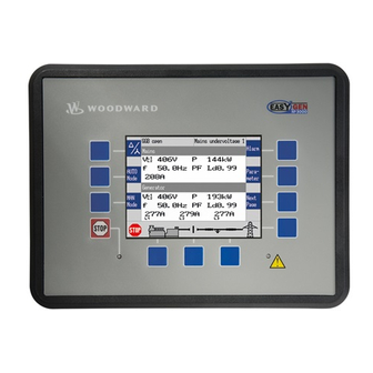
2.1 Display And Status Indicators
Explains the functions of the display and LEDs on the easYgen-3200 and easYgen-3100 units.
2.2 Hardware Interfaces (Terminals)
Details the various terminals and connectors provided by the easYgen-3100/3200 unit.
2.3 Application Modes Overview
Presents the basic functions provided by the genset control unit through different application modes.
3 Installation
3.1 Mount Unit (Sheet Metal Housing)
Provides instructions and dimensions for mounting the sheet metal housing variant of the unit.
3.2 Mount Unit (Plastic Housing)
Details the mounting procedure for the plastic housing variant, including clamp fasteners and screw kit installation.
3.3 Setup Connections
Covers general notes, wire sizes, and terminal allocation for connecting the device.
4 Configuration
4.1 Basic Setup
Covers basic setup parameters including language, clock, display, and password.
4.2 Configure Measurement
Details how to configure measurement parameters for generators, mains, and busbars, including dependencies.
4.3 Function Of Inputs And Outputs
Explains the grouping and pre-configuration of discrete inputs and outputs, including warnings.
4.4 Configure Monitoring
Describes various monitoring functions for generator, mains, engine, breaker, and miscellaneous parameters.
4.5 Configure Application
Covers configuration of breakers, inputs/outputs, controllers, and special applications.
5 Operation
5.1 Access Via PC (ToolKit)
Details the requirements and steps for installing the Woodward ToolKit software for PC access.
5.2 Front Panel Access
Provides information on accessing and navigating the front panel menus and screens.
5.3 Change Operating Modes
Explains how to change the operating modes of the unit, including STOP, MANUAL, and AUTOMATIC.
5.4 Restore Language Setting via HMI and Softkeys
Step-by-step guide on how to change the language setting via the HMI and softkeys.
6 Application
6.1 Application Modes Overview
Presents the basic functions provided by the genset control unit through different application modes.
6.2 Basic Applications
Details application modes A01 (None), A02 (GCBopen), A03 (GCB), and A04 (GCB/MCB).
6.3 Multiple Genset Applications
Covers overview, configuring automatic operation, and emergency operation for multiple genset systems.
6.4 Special Applications
Explains special applications like generator excitation protection, analog input setpoint control, and self-toggling relays.
7 Interfaces And Protocols
7.1 Interfaces Overview
Provides an overview of the interfaces supported by the control unit, including RS-232, RS-485, and CAN.
7.2 CAN Interfaces
Details CAN interface 1 (Guidance level) and CAN interface 2 (Engine level), including protocols and configurations.
7.3 Serial Interfaces
Covers the RS-232 interface (Serial Interface 1) and RS-485 interface (Serial Interface 2), including pin assignments.
7.4 CANopen Protocol
Explains the CANopen communication protocol and device profile specification for embedded systems.
8 Technical Specifications
8.1 Technical Data
Provides product label information and technical specifications for measuring values, currents, ambient variables, and inputs/outputs.
8.1.4 Interface
Details the specifications for RS-232, RS-485, and CAN bus interfaces, including insulation voltage and version.
8.1.5 Battery
Specifies the battery type, life span, and replacement policy.
8.1.6 Housing
Details the housing types (Plastic, Sheet metal), dimensions, wiring, and weight of the unit.
8.1.7 Approvals
Lists the EMC test results and relevant approvals, including CE, UL, CSA, BDEW, and VDE-AR-N 4105.
8.1.8 Generic Note
Provides general notes regarding accuracy and referred values.
8.2 Environmental Data
Specifies environmental data including vibration, shock, temperature, and humidity ratings.
8.3 Accuracy
Details the accuracy specifications for various measuring values like frequency, voltage, current, power, and power factor.
9 Appendix
9.1 Characteristics
Describes triggering characteristics for time-dependent overcurrent, two-level overshoot/undershoot, and phase rotation monitoring.
9.1.2 VDO Inputs Characteristics
Provides characteristic curves and tables for VDO inputs like pressure and temperature sensors.
9.2 Data Protocols
Details data protocols for CANopen/Modbus, including Protocol 5003 (Basic Visualization), 4103 (J1939), 4104 (J1939 Scania), 4105 (J1939 Deutz), 4110 (J1939 MTU), 5004 (Generator Values), 5005 (Mains Values), 5011 (Alarm Values).
9.2.4 Additional Data Identifier
Explains data identifiers for transmit data like remote control words, external discrete I/O, and analog outputs.
9.2.5 Protocol 65000 (External Discrete I/O 1 to 8)
Details the configuration and use of external discrete inputs and outputs for Phoenix expansion boards.
9.2.5.1
Describes the configuration of external analog inputs and outputs, including parameter IDs and supported sender types.
9.3 Analog Manager Reference
Provides reference for analog input and output configurations, including data sources and reference values.
9.4 LogicsManager Reference
Details the LogicsManager overview, logical symbols, logical command variables, and factory settings.
Table of Contents
Save PDF
Print
Rename the bookmark
Delete bookmark?
Delete from my manuals?
Login
Sign In
OR
Sign in with Facebook
Sign in with Google
Upload manual
Upload from disk
Upload from URL
Need help?
Do you have a question about the easYgen-3100 P1 and is the answer not in the manual?
Questions and answers