
Related Manuals for HP F5000

Summary of Contents for HP F5000
- Page 1 HP F5000 Firewall Installation Guide 5998-1413 Part number: 5998-1413 Document version: 6PW101-20121130...
- Page 2 The only warranties for HP products and services are set forth in the express warranty statements accompanying such products and services. Nothing herein should be construed as constituting an...
-
Page 3: Table Of Contents
Contents Product overview ·························································································································································· 1 F5000 physical architecture ············································································································································ 1 Main processing unit (NSQ1MPUA0) ···························································································································· 2 Interface modules ······························································································································································ 2 NSQ1GT8C40 ························································································································································· 2 NSQ1GT8P40 ·························································································································································· 3 NSQ1XP20 ······························································································································································· 3 Power supplies ··································································································································································· 3 ... - Page 4 Connecting Ethernet cables··········································································································································· 26 Connecting a copper Ethernet cable ··················································································································· 26 Connecting an optical fiber ································································································································· 27 Logging in to the firewall and configuring basic settings ······················································································· 30 Logging in to the firewall through the console port ···································································································· 30 ...
- Page 5 10A AC power cables used in different countries or regions ··················································································· 83 16A AC power cables used in different countries or regions ··················································································· 86 Support and other resources ····································································································································· 89 Contacting HP ································································································································································ 89 Subscription service ·············································································································································· 89 Related information ························································································································································ 89 ...
- Page 6 Index ··········································································································································································· 92 ...
-
Page 7: Product Overview
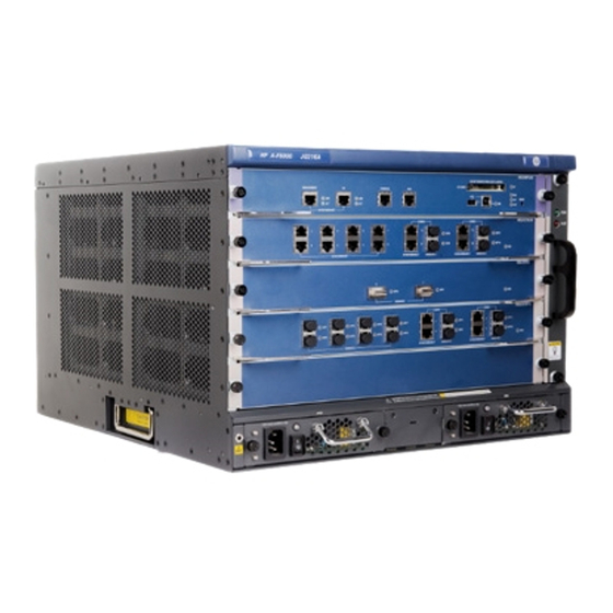
Product overview This chapter includes these sections: F5000 physical architecture • Main processing unit (NSQ1MPUA0) • Interface modules • • Power supplies Fan trays • F5000 physical architecture Figure 1 Front view (1) MPU slot (slot 0) (2) Fan tray... -
Page 8: Main Processing Unit (Nsq1Mpua0)
Figure 2 Rear view (1) Rear cover handle (do not use this handle to lift the chassis) (2) Air filter (optional) (3) Chassis handle (4) Grounding terminal and sign (5) Air vents Main processing unit (NSQ1MPUA0) Figure 3 NSQ1MPUA0 front panel (1) CF card button (2) CF card slot (3) Captive screw... -
Page 9: Nsq1Gt8P40
The NSQ1XP20 provides two XFP ports and supports the LAN PHY mode only. Figure 6 NSQ1XP20 front panel Power supplies The HP F5000 can be DC-powered or AC-powered. You can install two power supplies in your firewall, and they must be the same model. -
Page 10: Ac-Input Power Supply
The F5000 firewall uses hot swappable power supplies. You can install one power supply, or for redundancy, two power supplies for your firewall. AC-input power supply Figure 7 AC-input power supply front view (1) AC-input power receptacle (2) Power switch... -
Page 11: Fan Trays
Fan trays Figure 9 Fan tray (1) Handle (2) Fans... -
Page 12: Preparing For Installation
Preparing for installation This chapter includes these sections: Safety recommendations • Examining the installation site • Installation tools • • Accessories supplied by the firewall Checklist before installation • Safety recommendations Safety symbols When reading this document, note the following symbols: WARNING means an alert that calls attention to important information that if not understood or followed can result in personal injury. -
Page 13: Safety With Firewall Moving
Any attempt to carry the firewall with these parts may cause equipment damage or even bodily injury. Examining the installation site The F5000 firewall can only be used indoors. To ensure that the firewall works properly and to prolong its service lifetime, the installation site must meet the following requirements: Temperature and humidity •... -
Page 14: Altitude
The equipment room must also meet strict limits on salts, acids, and sulfides to eliminate corrosion and premature aging of components, as shown in Table Table 5 Harmful gas limits in an equipment room Max. (mg/m 0.006 0.05 0.01 Cooling system The F5000 firewall adopts left to right airflow for heat dissipation. -
Page 15: Esd Prevention
Figure 10 F5000 airflow Make sure there is enough space (greater than 10 cm (3.94 in)) around the air intake and outlet • vents on the firewall for good ventilation. • Make sure the installation site has a good cooling system. -
Page 16: Emi
Figure 11 Use an ESD-preventive wrist strap (1) ESD-preventive wrist strap (2) Lock (3) leash CAUTION: Check the resistance of the ESD-preventive wrist strap for safety. The resistance reading should be in the range of 1 to 10 megohm (Mohm) between human body and the ground. All electromagnetic interference (EMI) sources, from outside or inside of the firewall and application system, adversely affect the firewall in a conduction pattern of capacitance coupling, inductance coupling, electromagnetic wave radiation, or common impedance (including grounding system) -
Page 17: Rack-Mounting
Make sure the grounding terminal of the AC power receptacle is well grounded. • • Install a lightning arrester at the input end of the power supply to enhance the lightning protection capability of the power supply. Rack-mounting Before mounting the firewall in a rack, adhere to the following requirements: •... -
Page 18: Checklist Before Installation
Checklist before installation Table 6 Checklist before installation Item Requirements Result • There is a minimum clearance of 10 cm (3.94 in) around the inlet and exhaust vents for heat dissipation of the firewall chassis. Ventilation • A ventilation system is available at the installation site. - Page 19 Item Requirements Result • The rack is sturdy enough to support the weight of the firewall and installation accessories. Rack-mounting • The size of the rack is appropriate for the firewall. requirements • The front and rear of the rack are at least 0.8 m (31.50 in) away from walls or other devices.
-
Page 20: Installing The Firewall
Installing the firewall This chapter includes these sections: Installation flow • Check before installation • Installing the firewall in a 19-inch rack • • Grounding the firewall Installing an MPU • Installing an interface module • Installing a fan tray •... -
Page 21: Installation Flow
To mount multiple devices in the rack, mount the heavier equipment at a lower position. Installing the firewall in a 19-inch rack To install an F5000 to a rack, you need mounting brackets and rack shelves. Installing cage nuts to the rack... -
Page 22: Installing The Cable Management Brackets
Determine where to install the firewall in the rack, and then install a rack shelf to the rack. As shown in Figure 13, mark the positions of cage nuts on the front rack posts by using a front mounting bracket. Figure 13 Mark the positions of the cage nuts As shown in Figure... -
Page 23: Installing The Mounting Brackets To The Firewall
Figure 15 Install the cable management bracket (1) Left mounting bracket (2) Cable management bracket Installing the mounting brackets to the firewall NOTE: If you have ordered an air filter, install the air filter before installing the mounting brackets. For how to install an air filter, see “Installing an air filter (optional).”... -
Page 24: Installing The Firewall To The Rack
Installing the firewall to the rack Follow these steps to install the firewall to the rack: Put the firewall on the rack shelf, slide the firewall, and align the screw holes on the mounting brackets with the cage nuts on the rack. Fix the firewall horizontally by fastening the mounting brackets to the rack with appropriate pan head screws. -
Page 25: Installing An Mpu
Installing an MPU NOTE: • The F5000 supports only one MPU, which must be installed in slot 0. Typically the firewall does not provide a filler panel for slot 0 when it is shipped because you must install • an MPU to the slot for the firewall to operate. -
Page 26: Installing An Interface Module
Figure 19 Insert the MPU into slot Fasten the captive screws on the MPU with a Phillips screwdriver. After the firewall is powered on, the RUN LED flashes fast (at 8 Hz). It flashes slowly (at 1 Hz) after the application is loaded. This means that the MPU runs properly. For the LED description, see the chapter “Appendix B LEDs.”... -
Page 27: Installing A Fan Tray
Install the removed filler panels to prevent dust from entering the chassis. If slots 1 through 4 of the F5000 are all installed with interface modules, the interface modules are •... -
Page 28: Installing A Cf Card
Figure 21 Push the fan tray into the slot Use a Phillips screwdriver to fasten the captive screws on the fan tray. After the firewall is powered on, the RUN LED of the fan tray is steady on. This means that the fan tray runs properly. -
Page 29: Installing An Air Filter (Optional)
You must install the air filter before you install the mounting brackets. The air filter of the F5000 is installed at the air intake vents on the left of the chassis (when you face the front panel of the chassis) to prevent dust from entering the chassis. -
Page 30: Installing A Power Supply
Installing a power supply CAUTION: • The F5000 supports both AC and DC power supplies. You must install either AC or DC power supplies to the firewall. The F5000 needs only one power supply for the whole system to operate properly. -
Page 31: Connecting A Power Cord
NOTE: Typically the firewall does not provide a filler panel for one of the power supply slots. You can install a power supply in that slot. The procedures for installing an AC power supply and DC power supply are the same. The following uses an AC power supply as an example. -
Page 32: Connecting A Dc Power Cord
Figure 27 Connect an AC power cord to the firewall Connecting a DC power cord Follow these steps to connect a DC power cord: Switch off the DC power supply. Remove the protection cover from the DC power supply. Remove the screws from the terminals on the DC power supply with a Phillips screwdriver. Connect the end marked with “–... -
Page 33: Connecting An Optical Fiber
Connecting an optical fiber Before connecting the firewall to the network, you must install a transceiver module to the firewall, and then insert the fiber connector to the transceiver module. The A–F5000 supports LC connectors only. Follow these steps to connect optical fibers: Remove the dust plug from a fiber port of the firewall. - Page 34 Figure 30 Install the transceiver module Remove the dust cap from the transceiver module and the protective caps from the fibers. Plug the LC connectors on one end of the fiber cable into the Rx and Tx ports, and plug the LC connectors on the other end to the Tx and Rx ports on the peer device, as shown in Figure Figure 31 Connect the fiber connectors...
- Page 35 Never bend or curve a fiber when connecting it. The bend radius must be not less than 10 cm (3.94 • in). Figure 32 Bend radius of the fiber ≥10cm Ensure the cleanness of the fiber ends. • WARNING! To avoid injury to your eyes, do not stare at the optical interfaces and optical fiber connectors when connecting optical fibers.
-
Page 36: Logging In To The Firewall And Configuring Basic Settings
Logging in to the firewall and configuring basic settings This chapter includes these sections: • Logging in to the firewall through the console port Powering on the firewall • Logging in to the firewall through Telnet • • Logging to the firewall through a web browser Performing basic settings for the firewall •... -
Page 37: Setting Terminal Parameters
When you connect the console cable, HP recommends connecting the DB-9 connector of the console • cable to the serial port, and then the RJ-45 connector to the console port of the firewall. When you remove the console cable, HP recommends removing the RJ-45 connector, and then the DB-9 • connector. - Page 38 Figure 35 Set the serial port used by the HyperTerminal connection Click OK after selecting a serial port and the following dialog box appears. Set Bits per second to 9600, Data bits to 8, Parity to None, Stop bits to 1, and Flow control to None.
- Page 39 Figure 36 Set the serial port parameters NOTE: To use the default settings, click Restore Defaults. Click OK after setting the serial port parameters and the system enters the following interface. Figure 37 HyperTerminal window...
-
Page 40: Powering On The Firewall
Logging in to the firewall through Telnet NOTE: For more information about the Telnet login, see the configuration guides for the firewall. You can use the default information to log in to the F5000 firewall. The default login information includes: Username: admin •... -
Page 41: Logging To The Firewall Through A Web Browser
Log in to the F5000 through the console port and then use the telnet server enable command in system view to enable the Telnet function of the firewall. By default, Telnet is disabled on the firewall. Connect port M-GigabitEthernet 0/0 of the F5000 to a PC by using an Ethernet cable. -
Page 42: Performing Basic Settings For The Firewall
Performing basic settings for the firewall This section describes the fast configuration by using the basic configuration wizard. For more information about how to configure the protocols and features for the F5000 firewall, see the configuration guides for the firewall. -
Page 43: Configuring Service Management
Table 7 Basic information configuration items Item Description Sysname Set the system name. By default, the system name of the firewall is HP. Modify Current User Specify whether to modify the login password of the current user. Password To modify the password of the current user, set the new password and the confirm New Password password, and the two passwords must be identical. - Page 44 Figure 41 Basic configuration wizard: 3/6 (service management) Table 8 Service management configuration items Item Description Specify whether to enable FTP on the device. Disabled by default. Specify whether to enable telnet on the device. Telnet Disabled by default. Specify whether to enable HTTP on the device, and set the HTTP port number. Enabled by default.
-
Page 45: Configuring The Ip Address For An Interface
Item Description Specify whether to enable HTTPS on the device, and set the HTTPS port number. HTTPS is the HTTP protocol that supports the Secure Sockets Layer (SSL) protocol. It can improve device security. For more information about HTTPS. Disabled by default. IMPORTANT: •... -
Page 46: Configuring Nat
Table 9 Interface IP address configuration items Item Description Set the approach for obtaining the IP address, including: • None: The IP address of the interface is not specified, that is, the interface has no IP address. • Static Address: Specify the IP address for the interface IMPORTANT: manually;... -
Page 47: Completing The Configuration Wizard
Table 10 NAT configuration items Item Description Select an interface on which the NAT configuration will be applied. Generally, it is Interface the outgoing interface of the device. Specify whether to enable dynamic NAT on the interface. If dynamic NAT is enabled, the IP address of the interface will be used as the IP Dynamic NAT address of a matched packet after the translation. - Page 48 Figure 44 Basic configuration wizard: 6/6 This page lists all configurations you have made in the basic configuration wizard. Confirm the configurations. To modify your configuration, click Prev to go back to the previous page; if no modification is needed, click Finish to execute all configurations.
-
Page 49: Hardware Management And Maintenance
HP Comware Platform Software Comware Software, Version 5.20, Release 3206P18 Copyright (c) 2010-2011 Hewlett-Packard Development Company, L.P. HP F5000 uptime is 0 week, 0 day, 0 hour, 3 minutes 2048M bytes DDR2 SDRAM Memory 4M bytes Flash Memory 247M bytes CF0 Card MPUA PCB Version:Ver.B... -
Page 50: Displaying The Operational Statistics Of The Firewall
[SUBCARD 1] NSQ1GT8C40 (Hardware)Ver.B, (Driver)1.0, (Cpld)1.0 [SUBSLOT 2] The SubCard is not present [SUBSLOT 3] The SubCard is not present [SUBSLOT 4] The SubCard is not present Displaying the operational statistics of the firewall When you perform routine maintenance or the system fails, you may need to view the operational information of each functional module for locating failures. -
Page 51: Displaying The Electrical Label Information Of A Module
MPUA LX30T FPGA: 5.05 Driver : 1.0 SubCard Num : 5 CFCard Num Usb Num The SubCard1 on Board0: Status : Normal Type : NSQ1GT8C40 LPUA PCB 12GEA PCB LPUA Basic CPLD: LPUA Extend CPLD: 12GEA CPLD: LPUA LX30T FPGA: 5.05 LPUA LX110 FPGA:... -
Page 52: Displaying The Cpu Usage Of A Module
Displaying the CPU usage of a module Use the display cpu-usage command to display the CPU usage of the module in each slot. <Sysname> display cpu-usage Unit CPU usage: 3% in last 5 seconds 3% in last 1 minute 3% in last 5 minutes Table 11 Output description Field Description... -
Page 53: Displaying The Operational Status Of The Fan
Displaying the operational status of the fan Use the display fan command to display the operational status of the fan. <Sysname> display fan 1 State: Normal Table 13 Output description Field Description Number of the fan The fan state: • Normal—The fan is operating properly. -
Page 54: Viewing The System Fault Solving Method
Follow these steps to solve system faults: To do… Use the command… Remarks Enter system view system-view — Optional Specify the system fault solving system-failure { maintain | method for the MPU reboot } reboot by default for the MPU. NOTE: •... -
Page 55: Rebooting A Module Or The Firewall
Rebooting a module or the firewall To reboot a firewall, use one of the following methods: Use the reboot command to reboot a firewall. • Enable the scheduled reboot function at the CLI. You can set a time at which the firewall can •... -
Page 56: Replacement Procedures
Replacement procedures This chapter includes these sections: Safety recommendations • Replacing a power supply • Replacing an MPU • • Replacing an interface module Replacing a transceiver module • Replacing a CF card • Replacing a fan tray • Replacing an air filter •... -
Page 57: Replacing An Mpu
Figure 45 Pull out the power supply Install a new power supply. For how to install a power supply, see the chapter “Installing the firewall.” Replacing an MPU CAUTION: The MPU does not support hot swapping. Before replacing an MPU, you must switch off the power supply of the firewall. -
Page 58: Replacing An Interface Module
Replacing an interface module CAUTION: The interface module does not support hot swapping. Before replacing an interface module, you must switch off the power supply of the firewall. Follow these steps to replace an interface module: Switch off the power supply. Determine the interface module to be removed. -
Page 59: Replacing A Cf Card
Insert the dust cap to the removed transceiver module, and put the transceiver module into its original shipping materials. If you do not install a new transceiver module in the interface, install a dust-proof plug in the interface. For how to install a transceiver module, see the chapter “Installing the firewall.”... -
Page 60: Replacing A Fan Tray
Figure 49 Press the eject button Press the eject button again to eject the CF card part-way out of the CF card slot, and then pull the CF card out of the CF card slot. Figure 50 Press the eject button to eject the CF card Install a new CF card. -
Page 61: Replacing An Air Filter
Figure 51 Pull out the fan tray Install a new fan tray. For more information, see the chapter “Installing the firewall.” NOTE: Do not keep the firewall working without a fan tray for over two minutes because poor ventilation may •... - Page 62 Figure 52 Loosen the captive screws of the air filter Gently pull the air filter out along the slide rails. Figure 53 Pull the air filter out along the slide rails Install a new air filter. For more information, see the chapter “Installing the firewall.”...
-
Page 63: Troubleshooting
Troubleshooting This chapter includes these sections: MPU failures • Interface module failures • Power supply failures • • Fan failures Configuration system problems • Using the AUX port as the backup console port • Password loss • Cooling system failure •... -
Page 64: Alm Led Is Steady On Or Flashes
For example, the ALM LED is on when the system is over-temperature. In this case, the system displays the following output: %Jun 25 14:38:45:444 2010 HP DRVMSG/3/TempCritical: CPU temperature critical in Slot 3, index is 1. To solve the problem, check the output (such as the system temperature and PCB voltage alarms) on the serial terminal and the software management tool. -
Page 65: Red Power Led Is On
5 14:59:03:878 2010 HP DRVMSG/3/FanPlugIn:Fan 1 Plug In. %Jul 5 14:59:03:879 2010 HP DRVMSG/3/FanErr:Fan 1 Error. #Jul 5 14:59:03:998 2010 HP DEV/1/FAN STATE CHANGES TO FAILURE: Trap 1.3.6.1.4.1.2010.2.23.1.12.1.6: fan ID is 1 %Jul 5 14:59:03:998 2010 HP DEV/4/FAN FAILED: Fan 1 failed. -
Page 66: Configuration System Problems
To solve the problem, check whether any foreign object has entered the fan tray. If the cause cannot be located in the steps above and the problem persists, contact your local sales agent. Configuration system problems If the configuration environment setup is correct, the configuration terminal displays boot information when the firewall is powered on. -
Page 67: Password Loss
To do… Use the command… Remarks Enter system view system-view — Enter AUX user interface view user-interface aux 0 — Specify the none authentication mode authentication-mode none Required Configure the user privilege level user privilege level 3 Required NOTE: To use the default authentication mode (password authentication) for AUX port login, you must configure •... -
Page 68: Super Password Loss
NOTE: • To save the new password, execute the save command after modifying the user password. HP recommends saving the modification as the default configuration file. • Super password loss In the case of super password loss, you cannot perform higher level operations. -
Page 69: Host Software File Missing Errors
%May 14 21:37:35:271 2010 HP DRVMSG/3/Temp2High: Environment temperature too high in Slot 0, index is 2. #May 14 21:37:35:713 2010 HP DEV/1/BOARD TEMPERATURE UPPER: Trap 1.3.6.1.4.1.2010.2.23.1.12.1.16: frame Index is 0, slot Index 0.0 %May 14 21:37:35:713 2010 HP DEV/4/BOARD TEMP TOOHIGH: Board temperature is too high on Frame 0 Slot 0, type is MPU. - Page 70 Starting to get the backup application file--cfa0:/backup.bin! The backup application file does not exist--cfa0:/backup.bin! Starting to get the secure application file--cfa0:/secure.bin! The secure application file does not exist--cfa0:/secure.bin! Booting App fails! The name of the main, backup, and secure host software files vary by user settings. A possible reason for the errors is that the main, backup, and secure host software files have been deleted or damaged.
-
Page 71: Appendix A Technical Specifications
Appendix A Technical specifications Dimensions and weight Table 15 Dimensions and weight Item Specification Dimensions (H × W × D) (without mounting brackets) 308 × 436 × 476 mm (12.13 × 17.17 × 18.74 in) Weight (full configuration) 50 kg (110.23 lb) Power consumption range Table 16 Power consumption range of the entire system Item... -
Page 72: Fan Tray
Fan tray Table 19 Fan tray specifications Item Specification Rated voltage 12 VDC Total fan power consumption 50 W Dimensions (H × W × D) 227 × 31 × 413.3 mm (8.94 × 1.22 × 16.27 in) MPU (NSQ1MPUA0) Technical specifications Table 20 NSQ1MPUA0 specifications Item Specification... -
Page 73: Components
• 1 GB CAUTION: Use CF cards provided by HP only. The firewall may be incompatible with other CF cards. • The CF card is hot-swappable. When the CF card LED is flashing, do not unplug the CF card. Otherwise, •... - Page 74 The management Ethernet port is used only for managing the firewall and it has no service processing capabilities such as data forwarding. High Availability includes features such as stateful failover and VRRP. The HA port on the F5000 is a 10Base-T/100Base-TX/1000Base-T auto-sensing RJ-45 port, used to synchronize status packets in dual-device backup networking.
-
Page 75: Interface Modules
Interface modules NSQ1GT8C40 Table 24 NSQ1GT8C40 specifications Item Description DDR2 SDRAM Memory type and size 1 memory slot 512 MB (default), expandable to 1 GB 10 Mbps, half/full duplex Copper ports 100 Mbps, half/full duplex 1000 Mbps, full duplex 4 (copper/fiber) 10 Mbps, half/full duplex Combo interfaces Copper ports... -
Page 76: Nsq1Xp20
NSQ1XP20 Table 25 NSQ1XP20 specifications Item Description DDR2 SDRAM Memory type and 1 memory slot size 512 MB (default), expandable to 1 GB Power consumption Supported monitoring Dimensions (H × W 45.2 × 399.2 × 436.8 mm (1.78 × 15.72 × 17.20 in) ×... - Page 77 Item Description 4 (copper/fiber) 10 Mbps, half/full duplex Combo interfaces Copper ports 100 Mbps, half/full duplex 1000 Mbps, full duplex Fiber ports 1000 Mbps, full duplex Power consumption Supported monitoring Dimensions (H × W × D) 45.2 × 399.2 × 436.8 mm (1.78 × 15.72 × 17.20 in) Power consumption 70.2 W to 84 W Hot swapping...
-
Page 78: Appendix B Leds
Appendix B LEDs MPU LEDs Figure 54 LEDs on the MPU Table 27 Firewall running status LED description Status Description Management No link is present. port/HA port link A link is present. (green) status LED Management No data is being received or transmitted. port/HA port data transmission Data is being received or transmitted. -
Page 79: Interface Module Leds
Status Description The MPU is in standby state or is not powered on. The MPU is in active state. MPU status LED NOTE: (yellow) The firewall supports one MPU, so the MPU can only be in active state. The system is operating properly and there is no alarm. A fault has occurred to the system or the available power is insufficient. -
Page 80: Nsq1Xp20
Status Description No power input or the interface module is faulty. Slow flashing (1 Hz) The interface module is operating properly. The application software is being loaded (in this state, never power off the device or hot-swap the interface Fast flashing (8 Hz) (green) module;... -
Page 81: Power Supply Leds
Table 30 LED description Status Description No link is present on the corresponding port. Steady green A 1000 Mbps link is present on the port. Flashing green Data is being transmitted or received at 1000 Mbps. (yellow/green) Steady yellow A 10/100 Mbps link is present on the port. Flashing yellow Data is being transmitted or received at 10/100 Mbps. -
Page 82: Fan Tray Leds
Table 31 AC/DC power LED description Status Description Solid green The power supply is working properly. Power LED Solid red The power supply is faulty. No power is input. Fan tray LEDs Figure 60 Fan tray LEDs Table 32 Fan tray LED description Status Description The system is powered off or the fan tray is faulty. -
Page 83: Appendix C Cables
Appendix C Cables The HP F5000 firewall supports various types of interface modules. The port types vary by the interface module. Use dedicated cables to connect the ports of different types. Table 33 Cables Cable Applicable port type Description Connects the RJ-45 Ethernet port of... - Page 84 Figure 61 RJ-45 connector pinout PIN #8 PIN #1 NOTE: The RJ-45 Ethernet ports of the HP F5000 firewall use category 5 or higher Ethernet twisted pair cables for connection. EIA/TIA cabling specifications define two standards, 568A and 568B, for cable pinouts. •...
- Page 85 Figure 62 Straight-through cable Figure 63 Crossover cable Select an Ethernet twisted pair cable according to the RJ-45 Ethernet port type on your device. An RJ-45 Ethernet port can be MDI or MDIX. Table 35 Table 36 show their pinouts. Table 35 RJ-45 MDI port pinouts 10Base-T/100Base-TX 1000Base-T...
-
Page 86: Making An Ethernet Twisted Pair Cable
10Base-T/100Base-TX 1000Base-T Signal Function Signal Function Sends data BIDA- Bi-directional data cable A- Receives data BIDB+ Bi-directional data cable B+ Reserved BIDC+ Bi-directional data cable C+ Reserved BIDC- Bi-directional data cable C- Receives data BIDB- Bi-directional data cable B- Reserved BIDD+ Bi-directional data cable D+ Reserved... -
Page 87: Optical Fiber
Untwist the pairs so that they can lay flat, and arrange the colored wires based on the wiring specifications. Cut the top of the wires even with one another. Insert the wires into the RJ-45 end and make sure the wires extend to the front of the RJ-45 end and make good contact with the metal contacts in the RJ-45 end and in the correct order. - Page 88 Before connecting an optical fiber, make sure that the connector and cable type match the hot swappable interface module. NOTE: HP F5000 firewall provides shielded covers for the fiber ports (such as SFP ports). Before using such fiber ports, remove the shielded covers. Keep the shielded covers properly. When the fiber ports are not in use, install the shielded covers.
-
Page 89: Appendix D Ac Power Cables Used In Different Countries Or Regions
Appendix D AC power cables used in different countries or regions 10A AC power cables used in different countries or regions Table 39 10A AC power cables used in different countries or regions Countries or regions where the type of power Other countries or Countries or regions Connect... - Page 90 Holland, Denmark, Sweden, Finland, 04041056 (3 Indonesia, Turkey, F type Norway, Germany, India m, i.e., 9.8 ft) Russia, and CIS France, Austria, Belgium, and Italy Connector outline Power cable outline Connector outline Countries or regions where the type of power Other countries or Countries or regions Connect...
- Page 91 Connector outline Power cable outline Connector outline Countries or regions where the type of power Other countries or Countries or regions Connect cables conforms to local regions using this type seldom using this type Code (Length) or type safety regulations and of power cables of power cables can be used legally...
-
Page 92: Ac Power Cables Used In Different Countries Or Regions
16A AC power cables used in different countries or regions Table 40 16A AC power cables used in different countries or regions Countries or regions where the type of Countries or Other countries or Connector power cables regions seldom Code (Length) regions using this type of type conforms to local... - Page 93 Holland, Denmark, Sweden, Finland, 0404A061 (3 Indonesia, Turkey, F type Norway, Germany, m, i.e., 9.8 ft) Russia, and CIS France, Austria, Belgium, and Italy Connector outline Power cable outline Connector outline Countries or regions where the type of Countries or Other countries or Connector power cables...
- Page 94 0404A01A (3 I type Australia m, i.e., 9.8 ft) Connector outline Power cable outline Connector outline...
-
Page 95: Support And Other Resources
Related information Documents To find related documents, browse to the Manuals page of the HP Business Support Center website: http://www.hp.com/support/manuals For related documentation, navigate to the Networking section, and select a networking category. •... -
Page 96: Conventions
Conventions This section describes the conventions used in this documentation set. Command conventions Convention Description Boldface Bold text represents commands and keywords that you enter literally as shown. Italic Italic text represents arguments that you replace with actual values. Square brackets enclose syntax choices (keywords or arguments) that are optional. Braces enclose a set of required syntax choices separated by vertical bars, from which { x | y | ... - Page 97 Network topology icons Represents a generic network device, such as a router, switch, or firewall. Represents a routing-capable device, such as a router or Layer 3 switch. Represents a generic switch, such as a Layer 2 or Layer 3 switch, or a router that supports Layer 2 forwarding and other Layer 2 features.
- Page 98 (NSQ1MPUA0),66 Displaying hardware information of the firewall,43 failures,57 LEDs,72 Ethernet twisted pair cable,77 Examining the installation site,7 Optical fiber,81 F5000 physical architecture,1 Password loss,61 failures,59 Performing basic settings for the firewall,36 tray,66 Power consumption range,65 Fan tray LEDs,76 Power...
- Page 99 Replacing an interface module,52 Saving the current configuration of the firewall,48 Replacing an MPU,51 Solving system faults,47 Safety recommendations,6 Using the AUX port as the backup console port,60 Safety recommendations,50...
Need help?
Do you have a question about the F5000 and is the answer not in the manual?
Questions and answers