Sign In
Upload
Download
Table of Contents
Contents
Add to my manuals
Delete from my manuals
Share
URL of this page:
HTML Link:
Bookmark this page
Add
Manual will be automatically added to "My Manuals"
Print this page
×
Bookmark added
×
Added to my manuals
Manuals
Brands
CAME Manuals
Gate Opener
FA40230CB
Installation manual
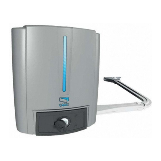
CAME FA40230CB Installation Manual
Operator for swing gates
Hide thumbs
Also See for FA40230CB
:
Installation manual
(38 pages)
,
Installation manual
(144 pages)
1
2
3
4
5
6
7
8
9
10
11
12
13
14
15
16
17
18
19
20
21
22
23
24
25
26
27
28
29
30
31
32
Table Of Contents
33
page
of
33
Go
/
33
Contents
Table of Contents
Bookmarks
Table of Contents
Intended Use
Packing List
Technical Data
Dimensions (MM)
Description of the Components
General Installation Instructions
Preliminary Checks
Installation
Power Supply
Warning Devices
Control Devices
Safety Devices
Function Menu
Motor Test
Run Calibration
Final Operations
Securing the Cover
Periodic Maintenance
Error Messages and Warnings
Dismantling and Disposal
Declaration of Conformity
Advertisement
Quick Links
1
Installation
2
Error Messages and Warnings
Download this manual
OPERATOR
119D W02EN
FOR SWING GATES
Installation manual
FA40230CB
EN
English
www.metalines.com
sales@metalines.com
Table of
Contents
Previous
Page
Next
Page
1
2
3
4
5
Advertisement
Table of Contents
Need help?
Do you have a question about the FA40230CB and is the answer not in the manual?
Ask a question
Questions and answers
Related Manuals for CAME FA40230CB
Gate Opener CAME FA40230CB Installation Manual
Operator for swing gates (144 pages)
Gate Opener CAME FA40230 Installation Manual
Operator for swing gates (38 pages)
Gate Opener CAME FA4024CB Installation Manual
Operator for swing gates (33 pages)
Gate Opener Came FA4024CB Installation Manual
Operator for swing gates (37 pages)
Gate Opener CAME FA70230CB Installation Manual
Swing-gate operator (25 pages)
Gate Opener CAME FA70230CB Installation Manual
Swing-gate operator (29 pages)
Gate Opener CAME FAST Series Mounting Procedure
Straight transmission arm (2 pages)
Gate Opener CAME FA70230E Installation Manual
Swing-gate operator (21 pages)
Gate Opener CAME FA70230 Installation Manual
(80 pages)
Gate Opener CAME FAST 70 Installation Manual
Operator for swing gates (128 pages)
Gate Opener CAME FA7024CB Installation Manual
Swing-gate operator (128 pages)
Gate Opener CAME FAST40 Installation Manual
Operator for swing gates (33 pages)
Gate Opener CAME 801XC-0180 Manual
(24 pages)
Gate Opener CAME FA01802M4A Getting Started
(21 pages)
Gate Opener CAME FAST70-P KIT Quick Setup Manual
Complete kit for a pair of swing gates weighing up to 200kg per leaf/max. width 2.3m (12 pages)
Gate Opener CAME FAST70-S KIT Quick Setup Manual
Complete kit for a single swing gate weighing up to 200kg / max. width 2.3m (13 pages)
This manual is also suitable for:
Fast40
Fast40-s
Fa40230
Fast40-p
Table of Contents
Print
Rename the bookmark
Delete bookmark?
Delete from my manuals?
Login
Sign In
OR
Sign in with Facebook
Sign in with Google
Upload manual
Upload from disk
Upload from URL


Need help?
Do you have a question about the FA40230CB and is the answer not in the manual?
Questions and answers