Table of Contents
Advertisement
Quick Links
Advertisement
Table of Contents

Subscribe to Our Youtube Channel
Related Manuals for Gefen DVI Detective Plus


Summary of Contents for Gefen DVI Detective Plus
- Page 1 ® DVI Detective Plus EXT-DVI-EDIDP User Manual www.gefen.com...
- Page 3 Chatsworth, CA 91311 www.gefen.com support@gefen.com Notice Gefen LLC reserves the right to make changes in the hardware, packaging, and any accompanying documentation without prior written notice. DVI Detective Plus is a trademark of Gefen LLC © 2013 Gefen, LLC. All rights reserved.
-
Page 4: Table Of Contents
CONTENTS Introduction Operation Notes Features Panel Layout Panel Descriptions Connecting the DVI Detective Plus Wiring Diagram EDID Programming Using a built-in EDID Writing an EDID using a source device/signal generator 10 Specifications 11 Warranty... -
Page 5: Introduction
Power is applied and the DVI Detective Plus reads and stores the display’s EDID to the internal memory on the DVI Detective Plus. Connect the DVI Detective Plus between the source and the display and it will never lose EDID again. -
Page 6: Operation Notes
OPERATION NOTES READ THESE NOTES BEFORE INSTALLING THE DVI DETECTIVE PLUS • Before programming the EDID, make sure all DIP switches are in the OFF (down) position and the write protect switch is in the E (write enabled) position. -
Page 7: Features
Supports resolutions up to 1920 x 1200, 2k, and 3840 x 2400 (Dual Link) • HDCP-compliant • No power required after initial programming • Compact unit hides well behind equipment Package Includes (1) DVI Detective Plus (1) 1 ft. DVI cable (M-M) (1) 5V DC power supply (1) Quick Start Guide... -
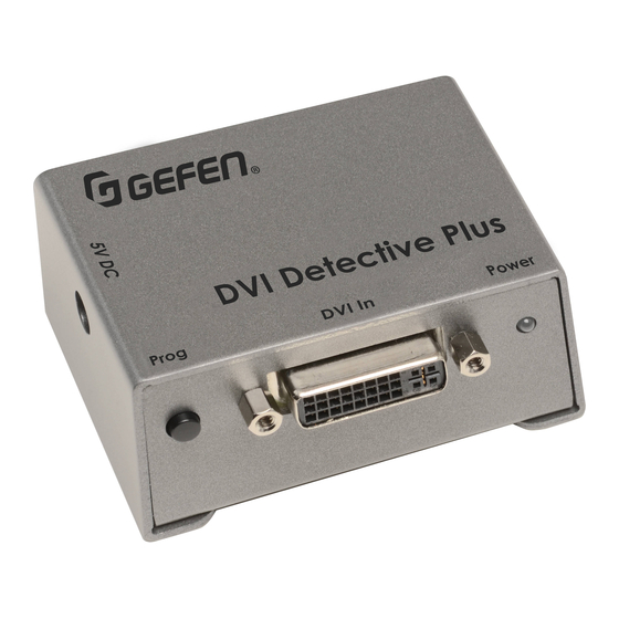
Page 8: Panel Layout
PANEL LAYOUT Front Back... -
Page 9: Panel Descriptions
PANEL DESCRIPTIONS Programming Button Press and hold this button to program an EDID. See page 8 for more information on recording an EDID. DVI In Connect the included DVI cable from this DVI port to the source device. DIP Switches Used to select pre-programmed EDIDS. -
Page 10: Connecting The Dvi Detective Plus
Set all four DIP switches in the OFF (down) position, as shown in the illustration below. Connect the included 5V DC power supply to the DVI Detective Plus. The power LED will glow bright green if the sink device contains a valid EDID. If the sink’s EDID is corrupt or invalid, then the power LED will glow bright red. -
Page 11: Wiring Diagram
Set the write switch to the “D” position (disabled) in order to prevent an accidental erasure of the stored EDID. Use the included DVI cable to connect the source to the DVI Detective Plus. IMPORTANT: If the source uses HDCP, then DIP switch 4 must be enabled (in the ON position) in order to enable HDCP pass-through. -
Page 12: Using A Built-In Edid
HD resolutions. Asterisks (“*”) indicate native resolutions. Make sure that the write switch on the DVI Detective Plus is in the “E” position and that all DIP switches are in the OFF (down) position. -
Page 13: Writing An Edid Using A Source Device/Signal Generator
OPERATING THE DVI DETECTIVE PLUS Writing an EDID using a source device/signal generator The DVI Detective Plus allows a signal generator (or other source device) to write an EDID to the Detective. This provides additional flexibility when programming custom timings and refresh rates. -
Page 14: Specifications
SPECIFICATIONS Maximum Pixel Clock ................165 MHz Input Video Signal..................1.2V p-p Input DDC Signal ................5V p-p (TTL) Video Input Connector ............DVI-I, 29-pin, female Video Output Connector ............DVI-I, 19-pin, female Power Supply ....................5V DC Power Consumption ................5W (max.) Dimensions (W x H x D) .... -
Page 15: Warranty
If equipment fails because of such defects and Gefen is notified within two (2) years from the date of shipment, Gefen will, at its option, repair or replace the equipment, provided that the equipment has not been subjected to mechanical, electrical, or other abuse or modifications. - Page 16 Rev A4 20600 Nordhoff St., Chatsworth CA 91311 1-800-545-6900 818-772-9100 fax: 818-772-9120 www.gefen.com support@gefen.com This product uses UL listed or CE compliant power supplies.
Need help?
Do you have a question about the DVI Detective Plus and is the answer not in the manual?
Questions and answers