Table of Contents
Advertisement
Quick Links
www.ti.com
User's Guide
TLIN1431EVM User's Guide
This user guide describes the TLIN1431-Q1 evaluation module (EVM). This EVM helps designers evaluate
the device performance, support fast development, and analyze automotive local interconnect network (LIN)
systems using the TLIN1431-Q1 family of LIN system basis chips (SBCs), which include wake functionality,
integrated high-side switch, and watchdog.
SLLU326 – MAY 2022
Submit Document Feedback
ABSTRACT
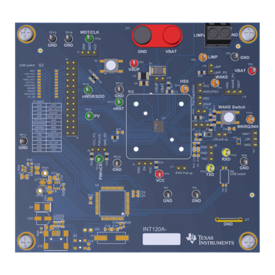
Figure 1-1. TLIN1431EVM Board Image
Copyright © 2022 Texas Instruments Incorporated
TLIN1431EVM User's Guide
1
Advertisement
Table of Contents

Related Manuals for Texas Instruments TLIN1431EVM


Summary of Contents for Texas Instruments TLIN1431EVM
- Page 1 (LIN) systems using the TLIN1431-Q1 family of LIN system basis chips (SBCs), which include wake functionality, integrated high-side switch, and watchdog. Figure 1-1. TLIN1431EVM Board Image SLLU326 – MAY 2022 TLIN1431EVM User's Guide Submit Document Feedback Copyright ©...
-
Page 2: Table Of Contents
Interface..................................8 3 Jumpers, Headers, Connectors, Test Points, and Switches....................9 4 Bill of Materials..................................11 Schematic....................................14 Trademarks All trademarks are the property of their respective owners. TLIN1431EVM User's Guide SLLU326 – MAY 2022 Submit Document Feedback Copyright © 2022 Texas Instruments Incorporated... -
Page 3: Introduction
Test point connections for each board signal 1.2 Description The TLIN1431EVM provides users with the ability to evaluate the TI TLIN1431-Q1 family of single-channel LIN SBCs, which include LDO, wake, high-side switch, watchdog, integrated battery voltage divider, LIMP, and channel expansion functionality. The EVM allows both commander and responder mode applications to be evaluated through the use of a single jumper that connects or disconnects the external 1 kΩ... -
Page 4: Evm Setup And Features
The TLIN1431-Q1 device has alternate pin designations and functions depending on the power-up mode chosen. The designations are shown in Table 2-1, and the functions of each pin are described in the TLIN1431- Q1 data sheet. TLIN1431EVM User's Guide SLLU326 – MAY 2022 Submit Document Feedback Copyright © 2022 Texas Instruments Incorporated... -
Page 5: Commander And Responder Configurations
This can be directly interfaced close to the device using J15, pin “WAKE” without a shunt. Applying a shunt to J15 applies a pull-up and allows the use of the WAKE switch on the board. SLLU326 – MAY 2022 TLIN1431EVM User's Guide Submit Document Feedback Copyright © 2022 Texas Instruments Incorporated... -
Page 6: Channel Expansion
¡ WAKE LIMP TLIN1431x-Q1 10 k ¤ nRST nINT DIV_ON Micro 20 pF LIN Controller SCI/UART TLIN1039 Figure 2-3. Channel Expansion with LIN Transceiver TLIN1431EVM User's Guide SLLU326 – MAY 2022 Submit Document Feedback Copyright © 2022 Texas Instruments Incorporated... -
Page 7: Vbat Voltage Divider
Note that LIMP_MCU and WAKE_MCU are outputs, and are not connected to LIMP and WAKE. Thus, for example. a signal cannot be applied to WAKE_MCU that would impact the high-voltage WAKE signal on the TLIN1431-Q1. SLLU326 – MAY 2022 TLIN1431EVM User's Guide Submit Document Feedback Copyright © 2022 Texas Instruments Incorporated... -
Page 8: High-Voltage Signal Monitoring
These four SPI signals can be connected to a micro controller or similar processor to control the TLIN1431-Q1 via SPI. Note that the device must start up with PIN/nCS (pin 7) floating or pulled high to interface via SPI mode. TLIN1431EVM User's Guide SLLU326 – MAY 2022 Submit Document Feedback Copyright © 2022 Texas Instruments Incorporated... -
Page 9: Jumpers, Headers, Connectors, Test Points, And Switches
Table 3-2, and Table 3-3 list all the jumpers, headers, connectors, test points, and switches on the TLIN1431EVM and explain the functions of each of these components. Table 3-1. Jumpers, Headers, and Connectors Designator Function Connector for WDT/CLK, with adjacent VCC and GND pins for WDT triggering, or GND referencing for CLK function. - Page 10 Push-button switch for WAKE interfacing, only active if J14 and J15 are appropriately connected as described in Section 2.3. Push-button switch for applying a strong pull-down to nRST as described in Section 2.6. TLIN1431EVM User's Guide SLLU326 – MAY 2022 Submit Document Feedback Copyright © 2022 Texas Instruments Incorporated...
-
Page 11: Bill Of Materials
Bill of Materials 4 Bill of Materials Table 4-1. TLIN1431EVM Bill of Materials Designator Quantity Value Description Part Number Manufacturer C1, C2, C3 0.1uF CAP, CERM, 0.1 uF, 50 V, +/- 10%, X7R, 0603 885012206095 Wurth Elektronik CAP, CERM, 1 uF, 50 V, +/- 10%, X7R, 0805... - Page 12 Bill of Materials www.ti.com Table 4-1. TLIN1431EVM Bill of Materials (continued) Designator Quantity Value Description Part Number Manufacturer Default shunt positioning: between pins of J10 2-881545-2 Default shunt positioning: between pins 1 and 2-881545-2 2 of J14 Default shunt positioning: between pins of J15 2-881545-2 LBL1 Thermal Transfer Printable Labels, 0.650"...
- Page 13 Bill of Materials Table 4-1. TLIN1431EVM Bill of Materials (continued) Designator Quantity Value Description Part Number Manufacturer TP17, TP19, TP20, Test Point, Multipurpose, Green, TH 5126 Keystone TP22, TP23 TP24, TP25 Test Point, Multipurpose, Yellow, TH 5014 Keystone Automotive LIN SBC with Integrated High-...
-
Page 14: Schematic
GPIO11/VEREF+ TSW-102-07-G-S 218-10LPST TSW-103-07-G-S GPIO9/ADC2 GPIO8/ADC3 218-2LPST LIMP TSW-102-07-G-S LIMP_PD 10.2k AIN_B_0 TSW-102-07-G-S nRST 22.0 100k EVQP1D05M 220pF 220pF Figure 5-1. TLIN1431EVM Schematic TLIN1431EVM User's Guide SLLU326 – MAY 2022 Submit Document Feedback Copyright © 2022 Texas Instruments Incorporated... - Page 15 STANDARD TERMS FOR EVALUATION MODULES Delivery: TI delivers TI evaluation boards, kits, or modules, including any accompanying demonstration software, components, and/or documentation which may be provided together or separately (collectively, an “EVM” or “EVMs”) to the User (“User”) in accordance with the terms set forth herein.
- Page 16 www.ti.com Regulatory Notices: 3.1 United States 3.1.1 Notice applicable to EVMs not FCC-Approved: FCC NOTICE: This kit is designed to allow product developers to evaluate electronic components, circuitry, or software associated with the kit to determine whether to incorporate such items in a finished product and software developers to write software applications for use with the end product.
- Page 17 www.ti.com Concernant les EVMs avec antennes détachables Conformément à la réglementation d'Industrie Canada, le présent émetteur radio peut fonctionner avec une antenne d'un type et d'un gain maximal (ou inférieur) approuvé pour l'émetteur par Industrie Canada. Dans le but de réduire les risques de brouillage radioélectrique à...
- Page 18 www.ti.com EVM Use Restrictions and Warnings: 4.1 EVMS ARE NOT FOR USE IN FUNCTIONAL SAFETY AND/OR SAFETY CRITICAL EVALUATIONS, INCLUDING BUT NOT LIMITED TO EVALUATIONS OF LIFE SUPPORT APPLICATIONS. 4.2 User must read and apply the user guide and other available documentation provided by TI regarding the EVM prior to handling or using the EVM, including without limitation any warning or restriction notices.
- Page 19 Notwithstanding the foregoing, any judgment may be enforced in any United States or foreign court, and TI may seek injunctive relief in any United States or foreign court. Mailing Address: Texas Instruments, Post Office Box 655303, Dallas, Texas 75265 Copyright © 2019, Texas Instruments Incorporated...
- Page 20 TI products. TI’s provision of these resources does not expand or otherwise alter TI’s applicable warranties or warranty disclaimers for TI products. TI objects to and rejects any additional or different terms you may have proposed. IMPORTANT NOTICE Mailing Address: Texas Instruments, Post Office Box 655303, Dallas, Texas 75265 Copyright © 2022, Texas Instruments Incorporated...
Need help?
Do you have a question about the TLIN1431EVM and is the answer not in the manual?
Questions and answers