Table of Contents
Advertisement
Quick Links
www.ti.com
User's Guide
TLC6983 48x16 Common Cathode Matrix LED Display
Driver Evaluation Module
This User's guide describes the TLC6983 evaluation module used as a reference for engineering demonstration
and evaluation. Included in this user's guide are setup instructions, a schematic diagram, printed board (PCB)
layout and a bill of materials (BOM).
1
Introduction.............................................................................................................................................................................2
1.1 Features.............................................................................................................................................................................
1.2
Applications........................................................................................................................................................................2
2 Test Setup and Results..........................................................................................................................................................
2.1 TLC6983 EVM Board.........................................................................................................................................................
2.2
Connectors.........................................................................................................................................................................3
2.3
Jumpers..............................................................................................................................................................................3
Setup................................................................................................................................................................................4
Layout...........................................................................................................................................................................6
Materials................................................................................................................................................7
5.1 Schematic..........................................................................................................................................................................
Materials...................................................................................................................................................................8
Figure 3-2. TLC6983EVM hardware setup..................................................................................................................................
Figure 4-1. TLC6983EVM Layout................................................................................................................................................
Figure 5-1. TLC6983 EVM Schematic.........................................................................................................................................
Parameters..........................................................................................................................................4
Table 5-1. TLC6983 EVM Bill of Materials...................................................................................................................................
Trademarks
All trademarks are the property of their respective owners.
SLVUC04 - DECEMBER 2020
Submit Document Feedback
ABSTRACT
Table of Contents
List of Figures
Board......................................................................................................................3
TM
connector pinout.........................................................................
List of Tables
TLC6983 48x16 Common Cathode Matrix LED Display Driver Evaluation
Copyright © 2020 Texas Instruments Incorporated
Table of Contents
2
3
3
7
4
5
6
7
8
1
Module
Advertisement
Table of Contents

Related Manuals for Texas Instruments TLC6983


Summary of Contents for Texas Instruments TLC6983
-
Page 1: Table Of Contents
Driver Evaluation Module ABSTRACT This User’s guide describes the TLC6983 evaluation module used as a reference for engineering demonstration and evaluation. Included in this user’s guide are setup instructions, a schematic diagram, printed board (PCB) layout and a bill of materials (BOM). -
Page 2: Introduction
The TLC6983 is a highly integrated common cathode matrix LED display driver with 48 constant current sources and 16 scanning FETs. A single TLC6983 is capable of driving 16 x16 RGB LED pixels while stacking two TLC6983s can drive 32 x 32 RGB LED pixels. To achieve low power consumption, the device supports separated power supplies for the red, green, and blue LEDs by its common cathode structure. -
Page 3: Test Setup And Results
J4 (5 V Jumper): Input 5 V power supply from J3 or J1/J2 • J4 (3 V3 Jumper): Input 3 V3 power supply from J3 (DCDC) or J1/J2 SLVUC04 – DECEMBER 2020 TLC6983 48x16 Common Cathode Matrix LED Display Driver Evaluation Submit Document Feedback Module Copyright © 2020 Texas Instruments Incorporated... -
Page 4: Test Setup
Disconnect J4 jumpers(5V/ 3V3) and connect TP1 and TP2 to 5V/GND power source. d. Power on 5V/GND power supply. Figure 3-2 shows the hardware setup of the TLC6983 by using USB Power. Figure 3-1. TLC6983EVM and MSP430F5529 LaunchPad connector pinout TLC6983 48x16 Common Cathode Matrix LED Display Driver Evaluation SLVUC04 –... -
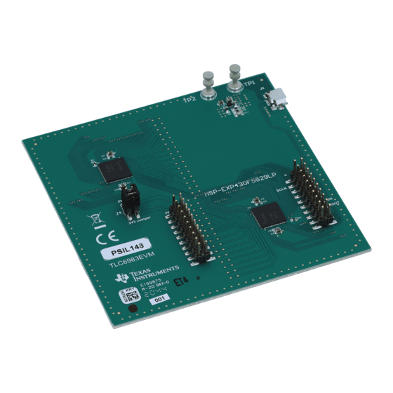
Page 5: Figure 3-2. Tlc6983Evm Hardware Setup
Test Setup Figure 3-2. TLC6983EVM hardware setup SLVUC04 – DECEMBER 2020 TLC6983 48x16 Common Cathode Matrix LED Display Driver Evaluation Submit Document Feedback Module Copyright © 2020 Texas Instruments Incorporated... -
Page 6: Board Layout
Board Layout www.ti.com 4 Board Layout Figure 4-1 illustrates the EVM Board Layout. Figure 4-1. TLC6983EVM Layout TLC6983 48x16 Common Cathode Matrix LED Display Driver Evaluation SLVUC04 – DECEMBER 2020 Module Submit Document Feedback Copyright © 2020 Texas Instruments Incorporated... -
Page 7: Schematic And Bill Of Materials
Schematic and Bill of Materials 5.1 Schematic TLC6983 EVM Schematic shows the EVM schematic. Figure 5-1. TLC6983 EVM Schematic SLVUC04 – DECEMBER 2020 TLC6983 48x16 Common Cathode Matrix LED Display Driver Evaluation Submit Document Feedback Module Copyright © 2020 Texas Instruments Incorporated... -
Page 8: Bill Of Materials
LED Display Driver with Ultra Low Power TPS62825DMQT Texas 2-A High Efficiency Synchronous DMQ0006A Instruments Buck Converter, DMQ0006A (VSON-HR-6) TLC6983 48x16 Common Cathode Matrix LED Display Driver Evaluation SLVUC04 – DECEMBER 2020 Module Submit Document Feedback Copyright © 2020 Texas Instruments Incorporated... - Page 9 STANDARD TERMS FOR EVALUATION MODULES Delivery: TI delivers TI evaluation boards, kits, or modules, including any accompanying demonstration software, components, and/or documentation which may be provided together or separately (collectively, an “EVM” or “EVMs”) to the User (“User”) in accordance with the terms set forth herein.
- Page 10 www.ti.com Regulatory Notices: 3.1 United States 3.1.1 Notice applicable to EVMs not FCC-Approved: FCC NOTICE: This kit is designed to allow product developers to evaluate electronic components, circuitry, or software associated with the kit to determine whether to incorporate such items in a finished product and software developers to write software applications for use with the end product.
- Page 11 www.ti.com Concernant les EVMs avec antennes détachables Conformément à la réglementation d'Industrie Canada, le présent émetteur radio peut fonctionner avec une antenne d'un type et d'un gain maximal (ou inférieur) approuvé pour l'émetteur par Industrie Canada. Dans le but de réduire les risques de brouillage radioélectrique à...
- Page 12 www.ti.com EVM Use Restrictions and Warnings: 4.1 EVMS ARE NOT FOR USE IN FUNCTIONAL SAFETY AND/OR SAFETY CRITICAL EVALUATIONS, INCLUDING BUT NOT LIMITED TO EVALUATIONS OF LIFE SUPPORT APPLICATIONS. 4.2 User must read and apply the user guide and other available documentation provided by TI regarding the EVM prior to handling or using the EVM, including without limitation any warning or restriction notices.
- Page 13 Notwithstanding the foregoing, any judgment may be enforced in any United States or foreign court, and TI may seek injunctive relief in any United States or foreign court. Mailing Address: Texas Instruments, Post Office Box 655303, Dallas, Texas 75265 Copyright © 2019, Texas Instruments Incorporated...
- Page 14 TI products. TI’s provision of these resources does not expand or otherwise alter TI’s applicable warranties or warranty disclaimers for TI products. Mailing Address: Texas Instruments, Post Office Box 655303, Dallas, Texas 75265 Copyright © 2020, Texas Instruments Incorporated...
Need help?
Do you have a question about the TLC6983 and is the answer not in the manual?
Questions and answers