Table of Contents
Advertisement
Quick Links
This document covers how the user can set up and use the TL16C750EEVM.
...................................................................................................................
1
2
3
4
5
6
7
........................................................................................................................
8
9
10
11
1
2
5.5 V to 3.3 V interface image
3
4
3.3 V LDO highlight image
5
6
3.3 V only control image
7
Loopback mode
...................................................................................................................
8
Mode select
9
.....................................................................................................................
10
.................................................................................................................
11
12
Schematic page 1
13
Schematic page 2
1
Trademarks
All trademarks are the property of their respective owners.
SLLU317 - January 2020
Submit Documentation Feedback
..................................................................................................................
............................................................................................
.............................................................................................................
.................................................................................................................
................................................................................................
................................................................................................................
...........................................................................................
....................................................................................................
.............................................................................................
..........................................................................................................
.................................................................................................
.............................................................................................................
....................................................................................................
..............................................................................................................
................................................................................................................
..........................................................................................................
..........................................................................................................
.............................................................................................................
Copyright © 2020, Texas Instruments Incorporated
TL16C750EEVM User's Guide
Contents
.............................................................................
.........................................................................
List of Figures
List of Tables
User's Guide
SLLU317 - January 2020
TL16C750EEVM User's Guide
2
2
4
5
6
7
9
10
10
11
12
2
3
4
5
6
7
8
9
10
11
11
12
13
14
1
Advertisement
Table of Contents

Related Manuals for Texas Instruments TL16C750EEVM


Summary of Contents for Texas Instruments TL16C750EEVM
-
Page 1: Table Of Contents
User's Guide SLLU317 – January 2020 TL16C750EEVM User's Guide This document covers how the user can set up and use the TL16C750EEVM. Contents ........................Introduction ................5 V Processor to 3.3 V V on TL16C750E ........................Input Power .................... Onboard 3.3 V LDO Regulator ................. -
Page 2: Introduction
• 5V processor to 3.3V DUT level translation Description This document will cover how to set up the TL16C750EEVM for evaluation. 5 V Processor to 3.3 V V on TL16C750E The below sections describes how to set up the EVM when using a 5 V digital logic processor to interface with the TL16C750E used at a 3.3 V logic. -
Page 3: Cc On Tl16C750E
CTS, and RX can be found at J23. The 5 V outputs DTR, RTS, OP, and TX can be located at J20.The 5V interfacing headers are highlighted in Figure Figure 2. 5.5 V to 3.3 V interface image SLLU317 – January 2020 TL16C750EEVM User's Guide Submit Documentation Feedback Copyright © 2020, Texas Instruments Incorporated... -
Page 4: Input Power
LDO denoted as D7. If more than 70 mA is being sourced by the LDO then D7 should be removed, and the connection between D7 can be shorted. Figure 3. Input Power Image TL16C750EEVM User's Guide SLLU317 – January 2020 Submit Documentation Feedback Copyright © 2020, Texas Instruments Incorporated... -
Page 5: Onboard 3.3 V Ldo Regulator
J10 should not be used as J10 is connected directly to the 3.3 V LDO net. The figure above shows J10 as do not use when the LDO is being used. Figure 4. 3.3 V LDO highlight image SLLU317 – January 2020 TL16C750EEVM User's Guide Submit Documentation Feedback Copyright © 2020, Texas Instruments Incorporated... -
Page 6: Using The Evm With The Dut At 3.3 V Or Lower
LDO but J10 would be removed if the 5 V input is to be used. The jumper positions described previously and in Figure 5 still apply. TL16C750EEVM User's Guide SLLU317 – January 2020 Submit Documentation Feedback Copyright © 2020, Texas Instruments Incorporated... -
Page 7: Loopback Mode
While TL16C750E does include an option to perform a loopback test through software, a hardware loopback test can be performed by shunting J21 like the Figure SLLU317 – January 2020 TL16C750EEVM User's Guide Submit Documentation Feedback Copyright © 2020, Texas Instruments Incorporated... - Page 8 Loopback mode www.ti.com Figure 7. Loopback mode TL16C750EEVM User's Guide SLLU317 – January 2020 Submit Documentation Feedback Copyright © 2020, Texas Instruments Incorporated...
-
Page 9: Mode Select
(this is done through the pull up resistor R2 on the PCB). Figure 8. Mode select SLLU317 – January 2020 TL16C750EEVM User's Guide Submit Documentation Feedback Copyright © 2020, Texas Instruments Incorporated... -
Page 10: Reset
Alternatively, a hardware reset switch is provided and denoted as S1. A reset is observed by D4 turning Figure 9. Reset image Silkscreen Errors on EVM Location Current Error Should Read Level Shifter Disabled Level Shifter Enabled Disable Enable Disable Enable TL16C750EEVM User's Guide SLLU317 – January 2020 Submit Documentation Feedback Copyright © 2020, Texas Instruments Incorporated... -
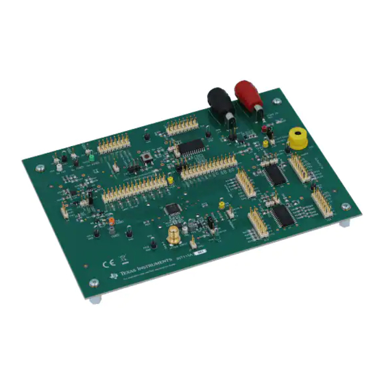
Page 11: Board Layout
Board Layout www.ti.com Board Layout Figure 10. EVM top Figure 11. EVM bottom SLLU317 – January 2020 TL16C750EEVM User's Guide Submit Documentation Feedback Copyright © 2020, Texas Instruments Incorporated... -
Page 12: Schematic And Bill Of Materials
INT 5V 4.7k TXRDY 5V RXRDY 5V INT TXRDY 5V 5V INT SN74LVC1T45DBVT 10.0k 3.3V TXRDY SN74LVC2T45DCTR 5V TXRDY Figure 12. Schematic page 1 TL16C750EEVM User's Guide SLLU317 – January 2020 Submit Documentation Feedback Copyright © 2020, Texas Instruments Incorporated... - Page 13 TPS70633DBVR Iout MAX = 150mA 3.3V VUART Figure 13. Schematic page 2 spacer spacer spacer spacer spacer spacer spacer spacer spacer spacer spacer spacer SLLU317 – January 2020 TL16C750EEVM User's Guide Submit Documentation Feedback Copyright © 2020, Texas Instruments Incorporated...
-
Page 14: 11.2 Bill Of Materials
Header, 2.54mm, 1x1, Gold, TH Header, 2.54mm, 1x1, HTSW-101-07-G-S Samtec J7, J9, J11, J15, J16, Header, 100mil, 2x1, Gold, TH 2x1 Header TSW-102-07-G-S Samtec J19, J21, J24, J25 TL16C750EEVM User's Guide SLLU317 – January 2020 Submit Documentation Feedback Copyright © 2020, Texas Instruments Incorporated... - Page 15 R86, R87, R88, R89 R17, R39 RES, 0, 5%, 0.125 W, 0603 0603 MCT06030Z0000ZP500 Vishay/Beyschl R24, R105 RES, 110, 5%, 0.125 W, 0805 0805 ERJ-6GEYJ111V Panasonic SLLU317 – January 2020 TL16C750EEVM User's Guide Submit Documentation Feedback Copyright © 2020, Texas Instruments Incorporated...
- Page 16 TXS0108EPWR Texas Texas Instruments And Push-Pull Application, PW0020A (TSSOP-20) Instruments ULTRA-LOW VOLTAGE PROCESSOR SUPERVISORY DBV0005A TPS3125L30DBVR Texas TPS3125L30DBVT Texas Instruments CIRCUIT, DBV0005A (SOT-23-5) Instruments TL16C750EEVM User's Guide SLLU317 – January 2020 Submit Documentation Feedback Copyright © 2020, Texas Instruments Incorporated...
- Page 17 SK02-0048QFP-CS-02A RS Tech Incorparated Note: Unless otherwise noted in the Alternate Part Number and/or Alternate Manufacturer columns, all parts may be substituted with equivalents. SLLU317 – January 2020 TL16C750EEVM User's Guide Submit Documentation Feedback Copyright © 2020, Texas Instruments Incorporated...
- Page 18 STANDARD TERMS FOR EVALUATION MODULES Delivery: TI delivers TI evaluation boards, kits, or modules, including any accompanying demonstration software, components, and/or documentation which may be provided together or separately (collectively, an “EVM” or “EVMs”) to the User (“User”) in accordance with the terms set forth herein.
- Page 19 www.ti.com Regulatory Notices: 3.1 United States 3.1.1 Notice applicable to EVMs not FCC-Approved: FCC NOTICE: This kit is designed to allow product developers to evaluate electronic components, circuitry, or software associated with the kit to determine whether to incorporate such items in a finished product and software developers to write software applications for use with the end product.
- Page 20 www.ti.com Concernant les EVMs avec antennes détachables Conformément à la réglementation d'Industrie Canada, le présent émetteur radio peut fonctionner avec une antenne d'un type et d'un gain maximal (ou inférieur) approuvé pour l'émetteur par Industrie Canada. Dans le but de réduire les risques de brouillage radioélectrique à...
- Page 21 www.ti.com EVM Use Restrictions and Warnings: 4.1 EVMS ARE NOT FOR USE IN FUNCTIONAL SAFETY AND/OR SAFETY CRITICAL EVALUATIONS, INCLUDING BUT NOT LIMITED TO EVALUATIONS OF LIFE SUPPORT APPLICATIONS. 4.2 User must read and apply the user guide and other available documentation provided by TI regarding the EVM prior to handling or using the EVM, including without limitation any warning or restriction notices.
- Page 22 Notwithstanding the foregoing, any judgment may be enforced in any United States or foreign court, and TI may seek injunctive relief in any United States or foreign court. Mailing Address: Texas Instruments, Post Office Box 655303, Dallas, Texas 75265 Copyright © 2019, Texas Instruments Incorporated...
- Page 23 TI products. TI’s provision of these resources does not expand or otherwise alter TI’s applicable warranties or warranty disclaimers for TI products. Mailing Address: Texas Instruments, Post Office Box 655303, Dallas, Texas 75265 Copyright © 2020, Texas Instruments Incorporated...
Need help?
Do you have a question about the TL16C750EEVM and is the answer not in the manual?
Questions and answers