Table of Contents
Advertisement
Quick Links
This user's guide describes the operational use of the TLV752-EVM evaluation module (EVM) as a
reference design for engineering demonstration and evaluation of the TLV75201DSQ, dual, high-accuracy,
adjustable linear regulator (LDO). Included in this user's guide are setup and operating instructions,
thermal and layout guidelines, a printed circuit board (PCB) layout, a schematic diagram, and a bill of
materials (BOM).
Throughout this document, the terms demonstration kit, evaluation board, and evaluation module are
synonymous with the TLV752-EVM.
Table 1
lists the related documentation available through the Texas Instruments web site at www.ti.com.
SBVU063 – December 2019
Submit Documentation Feedback
TLV752-EVM Evaluation Module
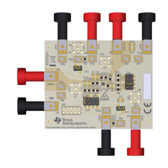
Figure 1. TLV752-EVM Evaluation Module
Table 1. Related Documentation
DEVICE
TLV752
Copyright © 2019, Texas Instruments Incorporated
LITERATURE NUMBER
SBVS383
TLV752-EVM Evaluation Module
User's Guide
SBVU063 – December 2019
1
Advertisement
Table of Contents

Subscribe to Our Youtube Channel
Related Manuals for Texas Instruments TLV752-EVM


Summary of Contents for Texas Instruments TLV752-EVM
-
Page 1: Tlv752-Evm Evaluation Module
TLV752-EVM Evaluation Module Figure 1. TLV752-EVM Evaluation Module This user’s guide describes the operational use of the TLV752-EVM evaluation module (EVM) as a reference design for engineering demonstration and evaluation of the TLV75201DSQ, dual, high-accuracy, adjustable linear regulator (LDO). Included in this user’s guide are setup and operating instructions, thermal and layout guidelines, a printed circuit board (PCB) layout, a schematic diagram, and a bill of materials (BOM). -
Page 2: Table Of Contents
Bottom Layer Routing ....................TLV752-EVM Schematic List of Tables ..................... Related Documentation ......................TLV752-EVM BOM Trademarks All trademarks are the property of their respective owners. TLV752-EVM Evaluation Module SBVU063 – December 2019 Submit Documentation Feedback Copyright © 2019, Texas Instruments Incorporated... -
Page 3: Introduction
Introduction Texas Instruments' TLV752-EVM helps design engineers evaluate the operation and performance of the TLV752 family of linear regulators for possible use in their own circuit application. This particular EVM configuration contains a single high-accuracy, small size, dual-input linear regulator for a wide range of applications. -
Page 4: Evm Setup
EVM Setup www.ti.com EVM Setup This section describes how to properly connect and set up the TLV752-EVM, including the jumpers and connectors on the EVM board. Inputs/Outputs Connectors and Jumper Descriptions 2.1.1 J1 – OUT1_S Regulated output voltage one sense 2.1.2... -
Page 5: Soldering Guidelines
To avoid damaging the integrated circuit (IC), use a hot-air system for any solder rework to modify the EVM for the purpose of repair or other application reasons. SBVU063 – December 2019 TLV752-EVM Evaluation Module Submit Documentation Feedback Copyright © 2019, Texas Instruments Incorporated... -
Page 6: Equipment Connection
2. Enable the outputs by jumping J11 (the EN1 pin) to VIN1 and J14 (the EN2 pin) to VIN2. 3. Vary the respective loads and input voltages, as necessary, for test purposes. TLV752-EVM Evaluation Module SBVU063 – December 2019 Submit Documentation Feedback Copyright © 2019, Texas Instruments Incorporated... -
Page 7: Pcb Layout
PCB layout for this EVM. Figure 2. Assembly Layer Figure 3. Top Layer Routing Figure 4. First Middle Layer Figure 5. Second Middle Layer SBVU063 – December 2019 TLV752-EVM Evaluation Module Submit Documentation Feedback Copyright © 2019, Texas Instruments Incorporated... - Page 8 PCB Layout www.ti.com Figure 6. Bottom Layer Routing TLV752-EVM Evaluation Module SBVU063 – December 2019 Submit Documentation Feedback Copyright © 2019, Texas Instruments Incorporated...
-
Page 9: Schematic
Schematic www.ti.com Schematic Figure 7 shows the schematic for this EVM. Figure 7. TLV752-EVM Schematic SBVU063 – December 2019 TLV752-EVM Evaluation Module Submit Documentation Feedback Copyright © 2019, Texas Instruments Incorporated... -
Page 10: Bill Of Materials
These assemblies must comply with workmanship standards IPC-A-610 Class 2. Unless otherwise noted in the Alternate Part Number or Alternate Manufacturer columns, all parts can be substituted with equivalents. TLV752-EVM Evaluation Module SBVU063 – December 2019 Submit Documentation Feedback Copyright © 2019, Texas Instruments Incorporated... - Page 11 TI products. TI’s provision of these resources does not expand or otherwise alter TI’s applicable warranties or warranty disclaimers for TI products. TI objects to and rejects any additional or different terms you may have proposed. IMPORTANT NOTICE Mailing Address: Texas Instruments, Post Office Box 655303, Dallas, Texas 75265 Copyright © 2022, Texas Instruments Incorporated...
Need help?
Do you have a question about the TLV752-EVM and is the answer not in the manual?
Questions and answers