Table of Contents
Advertisement
Quick Links
Advertisement
Table of Contents

Related Manuals for THORLABS PIA Series


Summary of Contents for THORLABS PIA Series
- Page 1 PIA Series Piezo Inertia Actuators User Guide Original Instructions...
-
Page 2: Table Of Contents
6.2 Waste Electrical and Electronic Equipment (WEEE) Directive ..... 16 6.3 Compliance ..................16 6.3.1 Waste treatment on your own responsibility ............. 17 6.3.2 Ecological background ..................17 6.4 CE Certificates ..................18 Chapter 7 Thorlabs Worldwide Contacts ........... 19 HA0360T Rev E Aug 2020... -
Page 3: Chapter 1 Safety
PIA Series Inertial Piezo Motor Actuators Chapter 1 Safety 1.1 Safety Information For the continuing safety of the operators of this equipment, and the protection of the equipment itself, the operator should take note of the Warnings, Cautions and Notes throughout this handbook and, where visible, on the product itself. -
Page 4: General Cautions
Chapter 1 1.2.1 General Cautions Caution Damage to the threads of the drive screw can cause significant inconsistency of stepping behaviour. The drive screw must not be obstructed. Dust and debris can reduce the lifetime of the actuator. If left running unattended for periods of time, the application should be covered where possible. -
Page 5: Chapter 2 Overview
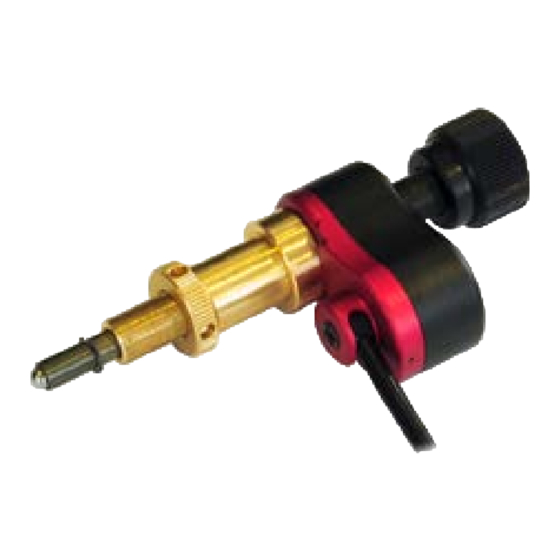
Using different rise and fall voltage rates depending on the load, a typical step size of 20 nm can be achieved. Thorlabs Piezo Inertia Actuators have been designed for use with our range of small positioning stages and optical mounts, and feature a 9.5 mm (3/8”) mounting barrel. - Page 6 Chapter 2 Manual Adjustment Knob Mounting Reference Surface 9.5 mm (3/8”) Mounting Barrel Locking Ring (included) 1/4”-80 Threaded Fine Drive Screw 1/4”-80 Thread for Mounting 110° (55° Left and Right) Mechanical Stop Adjustment of Cable Exit Fig. 2.2 PIAK10 Piezo Inertia Actuator - Features HA0360T Rev E Aug 2020...
-
Page 7: Chapter 3 Installation
Chapter 3 Installation 3.1 Mounting 3.1.1 General Cautions When mounting close to other equipment, ensure that the travel of the platform being driven is not obstructed. If movement is obstructed the actuator will stall, which could cause premature wear failure of the drive screw coating. -
Page 8: Adjusting The Cable Exit Position
Chapter 3 3.1.2 Adjusting the Cable Exit Position Caution The cable exit adjustment feature is for static use only, to set the appropriate cable exit angle. It is not for use in dynamic applications to achieve continuous flexing. The actuator should only be driven when the screw is locked. -
Page 9: Fitting To A Barrel Mount
PIA Series Inertial Piezo Motor Actuators 3.1.3 Fitting to a Barrel Mount Caution Only fit an actuator with the same travel as the stage. Fitting actuators with a longer travel will cause excessive axial preload. Do not exceed the preload values specified in Chapter 5. -
Page 10: Fitting To A Threaded Mount
Chapter 3 3.1.4 Fitting to a Threaded Mount Caution Only fit an actuator with the same travel as the stage. Fitting actuators with a longer travel will cause excessive axial preload. Do not exceed the preload values specified in Chapter 5. When adjusting the locking ring at items (2) and (5), take care to avoid damaging the threads by cross threading the ring. -
Page 11: Electrical Connections
The stage must be driven by a Thorlabs KIM101 controller (or legacy TIM101). The PIA series actuators are shipped with a 1 m (3.3’) cable, terminated in an SMC connector. Connect the PIA actuator to one of the MOT terminals on the rear panel of the KIM101 controller - see the KIM101 Controller handbook for pin out details. -
Page 12: Chapter 4 Operation
Chapter 4 Operation 4.1 General Caution The PIA series actuators can only be driven by the Thorlabs KIM101 or legacy TIM101 Controllers. Warning The piezo actuators in this product use high voltages. Voltages up to 130V may be present at the SMC connector. This is hazardous and can cause serious injury. -
Page 13: Maintenance
PIA Series Inertial Piezo Motor Actuators 4.2 Maintenance Periodically, the manual knob should be used to move the drive screw from one end of travel to the other, in order to redistribute the grease. The periodicity will depend on usage. In applications involving continuous use or where a small travel range is used at high duty cycle, the grease should be redistributed often to ensure optimal performance of the actuator. -
Page 14: Chapter 5 Specification
Chapter 5 Specification Parameter PIA13 PIA25 PIA50 PIAK10 Travel Range 13 mm (0.51”) 25 mm (0.98”) 50 mm (1.97”) 10 mm (0.39”) 20 nm 1, 2 Typical Step Size <30 nm Maximum Step Size Up to 30% Step Size Adjustability Maximum Step Frequency 2000 Hz Velocity (Cont. - Page 15 What applications can they be used for? Any ‘set-and forget’ application, particularly where space is tight. The primary function of the PIA series actuators is relative position and hold, whereby switching the controller off will result in the same drift as a 1/4-80 fine drive screw.
-
Page 16: Chapter 6 Regulatory
Chapter 7 Regulatory 7.1 Declarations Of Conformity 7.1.1 For Customers in Europe See Section 7.2. 7.1.2 For Customers In The USA This equipment has been tested and found to comply with the limits for a Class A digital device, persuant to part 15 of the FCC rules. These limits are designed to provide reasonable protection against harmful interference when the equipment is operated in a commercial environment. -
Page 17: Waste Treatment On Your Own Responsibility
PIA Series Inertial Piezo Motor Actuators 7.2 CE Certificates... -
Page 18: Chapter 7 Thorlabs Worldwide Contacts
Waste treatment is your own responsibility. "End of life" units must be returned to Thorlabs or handed to a company specializing in waste recovery. Do not dispose of the unit in a litter bin or at a public waste disposal site. - Page 20 Thorlabs Inc. Thorlabs Ltd. 56 Sparta Ave 1 Saint Thomas Place, Ely Newton, NJ07860 Cambridgeshire CB7 4EX, Tel: +1 973 300 3000 Tel: +44 (0) 1353 654440 Fax: +1 973 300 3600 Fax: +44 (0) 1353 654444 www.thorlabs.com www.thorlabs.com...
Need help?
Do you have a question about the PIA Series and is the answer not in the manual?
Questions and answers