Table of Contents
Advertisement
Quick Links
Advertisement
Table of Contents

Related Manuals for Varifan VPM-1


Summary of Contents for Varifan VPM-1
- Page 1 VPM-1 User’s Manual www.monitrol.com...
- Page 2 Although the manufacturer has made every effort to ensure the accuracy of the information contained herein, this document is subject to change without notice due to ongoing product development. WARNINGS AND PRECAUTIONS Equipment, probe failure, blown fuses and/or tripped breakers may prove harmful to the contents of the building.
-
Page 3: Table Of Contents
TABLE OF CONTENTS INTRODUCTION General ................4 Description ............... 4 INSTALLATION Unpacking ................ 6 Mounting ................6 Connection Procedure ............. 7 2.3.1 Cabling ................7 2.3.2 Connecting 115 VAC Fan ..........7 2.3.3 Connecting 230 VAC Fan ..........7 2.3.4 Connecting to the master control ........ -
Page 4: Introduction
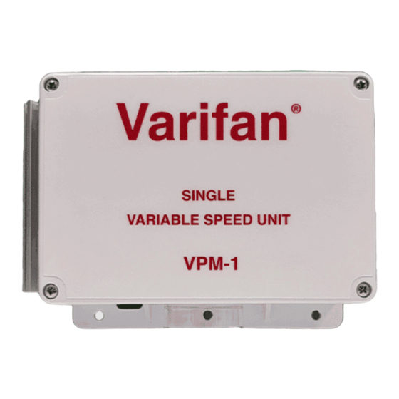
User’s Guide • Appendix 1.1 DESCRIPTION The VPM-1 is designed to drive one variable speed fan of up to 6 amp per stage, under the master control ( LX or IC) system resulting in a clean air environment for your livestock. - Page 5 INSTALLATION INSTALLATION Page 5 www.monitrol.com...
-
Page 6: Unpacking
VPM-1 2.1 UNPACKING Unpack the VPM-1 from its box and inspect contents for damage. Should the contents appear to be damaged, contact your local distributor for return material procedures. The package should contain the following standard items: • 1 VPM-1 control •... -
Page 7: Connection Procedure
INSTALLATION 2.3 CONNECTION PROCEDURE For the connection procedures which follow refer to Figures 1 and 2. 2.3.1 - Wiring Use a screwdriver to remove cable knock-outs for the installation of cabling to the unit. Knock-outs may be difficult to remove, drill out if possible. It is strongly recommended to install PVC conduits. -
Page 8: Connecting To The Master Control
500 feet (150m). • Connect one end of the cable to the (+) and (-) terminals of the VPM-1 low voltage terminal block. Refer to the bottom left corner of figures 1 or 2. • All wires between the master control and the VPM- 1, as well as the probes should be shielded. - Page 9 INSTALLATION Figure. 1 Main Board: Connection of 115 VAC source and 115 VAC fan Notes for Figure 1 Power cut and protection devices in case of overload. Connect the grounding wire from the power cord to the ground terminal wire inside the housing. Page 9 www.monitrol.com...
- Page 10 VPM-1 Figure. 2 Main Board: Connection of 230 VAC source and 230 VAC fan Notes for Figure 2 Power cut and protection devices in case of overload. Connect the grounding wire from the power cord to the ground terminal wire inside the housing.
-
Page 11: User's Guide
USER’S GUIDE USER’S GUIDE Page 11 www.monitrol.com... - Page 12 VPM-1 The VPM-1 is a single variable speed unit able to drive one or several fans in a single stage. The fan speed is controlled accordingly to the logic of the master control, the LX or IC control. The VPM-1 can be controlled manually from the master control to: •...
-
Page 13: Appendix
APPENDIX APPENDIX Page 13 www.monitrol.com... -
Page 14: Troubleshooting
IC to allow fans to operate. The unit Are the fan (s) operating? is OK. Verify the power connection to the VPM-1 fuses, and fans. Also the low voltage cable between the LX or IC and the VPM. Contact your... - Page 15 WARRANTY Limited Warranty manufacturered equipment supplied components have gone through rigorous inspection to assure optimal quality of product and reliability. Individual controls are factory tested under load, however the possibility of equipment failure and/or malfunction may still exist. For service, contact your local retailer or supplier. The warranty period shall be for two years from manufacturing date.
- Page 16 MAV VPM-1 VER:2.1 JUNE 22,2001 www.monitrol.com...
Need help?
Do you have a question about the VPM-1 and is the answer not in the manual?
Questions and answers