Advertisement
Quick Links
IMPORTANT
Carefully remove all the parts from the carton and
place them individually on a soft cloth to prevent
scratches or other damage.
Carefully and strictly follow these assembly instructions
to ensure a completed product as designed.
Do not use power tools above 8 volts to assemble.
Part List
A.
Middle Panel
1 pc.
B.
Front Rail
1 pc.
C.
Shelf
4 pcs.
D.
Base
1 pc.
N.
Top
1 pc.
O.
Front Rail
1 pc.
Hardware List
Hex Wrench
1 pc.
Small Hex Wrench
1 pc.
Tool(s) required for assembly: Phillips screwdriver, Level, Drill (8 volts or less), 3/8" Drill Bit
home
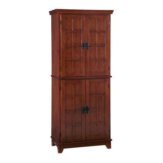
5180-64
Pantry
F.
E.
Side Panel
Side Panel
1 pc.
1 pc.
Q.
P.
Side Panel
Side Panel
1 pc.
1 pc.
M3.5x16
Cam Lock Screw
Wood Screw
16 pcs. (+1 extra)
28 pcs. (+1 extra)
Cam Lock
Adjustable Pin
28 pcs. (+4 extra)
16 pcs. (+1 extra)
styles Customer Service: www.homestylesfurniture.com,
servicedesk@homestylesfurniture.com,
G.
H.
Door
Door
1 pc.
1 pc.
K.
Leg
2 pcs.
S.
R.
Door
Door
1 pc.
1 pc.
M6x35
Head Cap Bolt
4 pcs. (+1 extra)
Flat Washer
4 pcs. (+1 extra)
888-680-7460
J.
I.
Back Upright
Back Panel
2 pcs.
1 pc.
M.
Back Rail
4 pcs.
U.
T.
Back Panel
Back Upright
1 pc.
2 pcs.
Spring Washer
4 pcs. (+1 extra)
M4x15
Machine Screw
Handle
8 pcs.
4 pcs.
Advertisement

Related Manuals for Home Styles 5180-64


Summary of Contents for Home Styles 5180-64
- Page 1 5180-64 Pantry IMPORTANT Carefully remove all the parts from the carton and place them individually on a soft cloth to prevent scratches or other damage. Carefully and strictly follow these assembly instructions to ensure a completed product as designed. Do not use power tools above 8 volts to assemble.
- Page 2 Assembly Instructions 2/8 IMPORTANT Ÿ Use a soft cloth between these parts and the floor. Ÿ Do not use power tools above 8 volts to assemble. Ÿ Do not tighten all the bolts until each part is properly assembled. Ÿ The unit must be level to work properly.
- Page 3 Assembly Instructions 3/8 Cam Lock STEP 2 Attach Back Rail (M) to Side Panel (F) with Cam Lock. (See Figure 2) Attach Back Upright (J) to Back Rail (M). Slide Back Panels (I) into position. Attach Back Rail (M) to unit with Cam Lock.
- Page 4 Assembly Instructions 4/8 STEP 4 Head Cap Bolt Spring Washer Flat Washer Attach Base (D) to unit with Cam Locks. Attach Legs (K) to unit with Flat Washers, Spring Washers and Head Cap Bolts. (See Figure ) 3 Cam Lock Figure 3 Cam Lock STEP 5...
- Page 5 Assembly Instructions 5/8 Cam Lock STEP 6 Attach Back Rail (M) to Side Panel (Q) with Cam Lock. Attach Back Upright (U) to Back Rail (M). Slide Back Panels (T) into position. Attach Back Rail (M) to unit with Cam Lock. Cam Lock STEP 7 Attach Front Rail (O)
- Page 6 Assembly Instructions 6/8 Cam Lock STEP 8 Turn unit over to its upright position. Attach Top (N) to unit with Cam Locks. Cam Lock STEP 9 Attach unit from Step 8 to unit from Step 5 with Cam Locks.
- Page 7 Assembly Instructions 7/8 STEP 10 Insert Adjustable Pins into side panels at desired level. Place Shelves (C) into position. Attach Doors (G), (H), (R) and (S) to unit by sliding door hinges into side panel hinges. (See Figure ) 4 Attach Handles to Doors (G), (H), (R) and (S) with Machine Screws.
-
Page 8: Hardware List
Assembly Instructions / 8 8 IMPORTANT Ÿ To help reduce the risk of the unit tipping over, the Tipover Restraint must be installed following these instructions exactly. STEP 12 Wall Screw Pre-drilled hole Anchor in wall Bracket at top of unit on wall Wood Screw 3/8”... - Page 9 Digital images of the defective parts may be required. If the product was not purchased from an authorized retailer, home styles is under no obligation to provide replacement parts. Parts are not available for fully assembled items nor are parts available for sale. Replacements for missing or damaged parts may be requested via contact info below.
Need help?
Do you have a question about the 5180-64 and is the answer not in the manual?
Questions and answers