Advertisement
Quick Links
IMPORTANT
Carefully remove all the parts from the carton and
place them individually on a soft cloth to prevent
scratches or other damage.
Carefully and strictly follow these assembly instructions
to ensure a completed product as designed.
Do not use power tools above 8 volts to assemble.
Part List
A.
Seat
1 pc.
E.
Base
1 pc.
F.
Foot
1 pc.
L.
M.
Back Support
Post
2 pcs.
1 pc.
Tool(s) required for assembly: Phillips screwdriver, Level, Drill (8 volts or less), 3/8" Drill Bit
Home Styles Customer Service: www.homestyles-furniture.com,
servicedesk@homestyles-furniture.com,
20 05186 0049
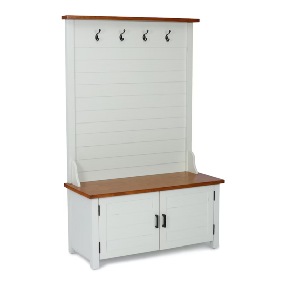
Hall Tree
B.
Side Panel
1 pc.
G.
H.
Support
Back Panel
2 pcs.
1 pc.
O.
Top
1 pc.
N.
Post
1 pc.
C.
Side Panel
1 pc.
P.
Q.
Door
Door
1 pc.
1 pc.
R.
Shelf
2 pcs.
888-680-7460, 877-831-0319
D.
Middle Panel
1 pc.
I.
Back Panel
1 pc.
J.
Back Panel
1 pc.
K.
Back Panel
1 pc.
Advertisement

Subscribe to Our Youtube Channel
Related Manuals for Home Styles 20 05186 0049


Summary of Contents for Home Styles 20 05186 0049
- Page 1 2 pcs. 1 pc. 1 pc. 1 pc. 1 pc. Shelf Back Panel 2 pcs. 1 pc. Tool(s) required for assembly: Phillips screwdriver, Level, Drill (8 volts or less), 3/8” Drill Bit Home Styles Customer Service: www.homestyles-furniture.com, servicedesk@homestyles-furniture.com, 888-680-7460, 877-831-0319...
-
Page 2: Hardware List
8 pcs. (+1 extra) 4 22 M3.5x25 Machine Screw Flat Head Screw (long) Cam Lock Screw Cam Lock 4 pcs. 12 pcs. (+1 extra) 14 pcs. (+2 extra) 14 pcs. (+4 extra) Handle 2 pcs. Home Styles Customer Service: www.homestyles-furniture.com, servicedesk@homestyles-furniture.com, 888-680-7460, 877-831-0319... - Page 3 Assembly Instructions 3/9 IMPORTANT Ÿ Use a soft cloth between these parts and the floor. Ÿ Do not use power tools above 8 volts to assemble. Ÿ Do not tighten all the bolts until each part is properly assembled. Ÿ The unit must be level to work properly.
- Page 4 Assembly Instructions 4/9 Cam Lock Screw Figure 4 STEP 3 Insert Cam Lock Screws into pre-drilled holes in Seat (A), Posts (M), (N) and Top (O), then tighten. (See Figure 4) Flat Head Screw (long) Arrow label pointing to Back Panel (I) Figure 5 STEP 4 Orientate Back Panel (J) with Arrow label pointing to Back Panel (I),...
- Page 5 Assembly Instructions 5/9 Figure 6 Head Cap Bolt Spring Washer Flat Washer Cam Lock STEP 5 Attach Posts (M) and (N) to unit with Cam Locks. (See Figure 6) Attach Top (O) to unit with Head Cap Bolts, Spring Washers, Flat Washers and Cam Lock.
- Page 6 Assembly Instructions 6/9 Head Cap Bolt Magnet Screw Spring Washer Magnet Flat Washer Figure 7 Head Cap Bolt (long) Spring Washer Flat Washer Cam Lock STEP 6 Attach Supports (G) to unit with Head Cap Bolts (long), Spring Washers and Flat Washers. Attach Magnets to Seat (A) with Magnet Screws.
- Page 7 Assembly Instructions 7/9 Flat Head Screw Hook Figure 8 Figure 9 Lock Flat Washer Spring Washer Head Cap Bolt (short) STEP 7 Turn unit to its upright position. Attach Doors (P) and (Q) to unit from Step 2 by sliding door hinges into side panel hinges.
- Page 8 Assembly Instructions 8/9 Figure 10 Figure 11 Adjustable Pin Machine Screw Handle STEP 8 Attach Handles to Doors (P) and (Q) with Machine Screws. (See Figure 10) Insert Adjustable Pins into side panels and middle panel at desired level. (See Figure 11) Place Shelves (R) into position.
- Page 9 Assembly Instructions 9/9 IMPORTANT Ÿ To help reduce the risk of the unit tipping over, the Tipover Restraint must be installed following these instructions exactly. STEP 9 Anchor in wall Wall Screw Pre-drilled hole Bracket Place unit at desired location. on wall at top of unit 3/8”...
- Page 10 Buff with a dry clean cloth. Home Styles will provide replacements free of charge for missing or damaged hardware or parts within 30 days of purchase. Digital images of the defective parts may be required. If the product was not purchased from an authorized retail affiliate, Home Styles is under no obligation to provide replacement parts.
Need help?
Do you have a question about the 20 05186 0049 and is the answer not in the manual?
Questions and answers