Table of Contents
Advertisement
Quick Links
Advertisement
Table of Contents

Subscribe to Our Youtube Channel
Related Manuals for R.V.R. Elettronica HC5-10


Summary of Contents for R.V.R. Elettronica HC5-10
- Page 1 HC5-10 User Manual Volume 1 Manufactured by Italy...
- Page 2 Storia del documento Data Versione Ragione Autore 26/03/04 Prima versione J.Berti HC5-10 - Manuale Utente Versione 1.0 © Copyright 2004 R.V.R. Elettronica SpA Via del Fonditore 2/2c - 40138 - Bologna (Italia) Telefono: +39 051 6010506 Fax: +39 051 6011104 Email: info@rvr.it...
-
Page 3: Table Of Contents
HC5-10 Table of Contents 1. Preliminary Instructions 2. Warranty 3. First Aid 3.1 Treatment of electrical shocks 3.2 Treatment of electrical Burns 4. General Description 5. Quick reference to instalaltion and use 5.1 Preparation 5.2 Operation 5.3 Software 6. Controls, Indicators and Connectors 6.1 Front Panel... - Page 4 HC5-10 This page was intentionally left blank Rev. 1.0 - 26/03/04 Manuale Utente...
-
Page 5: Preliminary Instructions
In a residential place this equipment can cause hash. In this case can be requested to user to take the necessary measures. R.V.R. Elettronica SpA reserves the right to modify the design and/or the technical specifications of the product and this manual without notice. -
Page 6: First Aid
HC5-10 If your dealer cannot help you, contact R.V.R. Elettronica and explain the problem. If it is decided to return the unit to the factory, R.V.R. Elettronica will mail you a regular authorization with all the necessary instructions to send back the goods. -
Page 7: Treatment Of Electrical Burns
HC5-10 Figure 3 Figure 4 Figure 5 • In case of only one rescuer, 15 compressions alternated to two breaths. • If there are two rescuers, the rythm shall be of one brath each 5 compressions. • Do not interrupt the rythm of compressions when the second person is giving breath. -
Page 8: General Description
RF amplified signal to be forwarded to the antenna output. The HC5-10 is produced in the version for five transmitters of 2 kW max output power everyone (for example PJ2000M-C), for a total nominal power of 10 kW. - Page 9 HC5-10 “AUX OUT AC LINE”. This plug is in fact opened using a relay under the same conditions that cause the activation of the interlock.
-
Page 10: Quick Reference To Instalaltion And Use
5.1 Preparation Unpack the HC5-10 and before any other operation check the unit for any shipping damage; in particular, check that all the controls and connectors on the front and rear panels are in good conditions. -
Page 11: Operation
RF power and the power supply. When the HC5-10 comes put under voltage, verify that the two ON LED are lit. The LCD display shows a presentatio screen, and after a few seconds it will pass to the default screen, showing the values of the forward and reflected power. - Page 12 "Remote", therefore in condition of answer to the deriving commands from the HC5-10. The set of the apparatus HC5-10, instead, could be select on the base of the option foreseen from the plan of the station. The HC5-10 could be commanded through telemetry or from the operator, in the first case must be set in "Remote,"...
- Page 13 "Remote." 5.2.2 General norms of di funzionamento con PJ2000M-C The normal functioning of the HC5-10 system with PJ2000M-C foresees that the five amplifiers apparatuses are working with equal output powers and electrical phase of their signals equalized to the input of the combiner.
- Page 14 200W and/or when the temperature of the warmer resistance exceeds 40 °C. When the emergency fans group enters in function, on the frontal panel of the HC5-10 an yellow LED, with "Fans On" label, is lit on.
- Page 15 HC5-10 5.2.4 Protection Circuits The HC5-10 apparatus disposes of protection circuits that arrest temporarily and/or definitely the functioning of the whole transmitter system. 1) Protection from excessive output forward power "Fwd PWR". It intervenes at 12.5KW, and it effect until to 8 attempts in the short period; exhausted the restoration attempts blocks the apparatus definitely, signalling the status with a "Fault"...
- Page 16 Remedy: Reduce the power of all the transmitter adjusting the trimmer "Power Adjust", on the HC5-10 frontal panel, until to obtain a value of "Rej PWR" inferior to 200W. Anomaly: When the signal phase regulation of the 5 amplifiers is not optimized, the power on resistances absorbers "Rej PWR"...
- Page 17 HC5-10 When left one phase of the mains power, that is not what it feeds the HC5-10, the transmitter reduces its RF output power to a value that doesn't exceed the 5KW. If the power of programmed regime is inferior to the value of 5KW, doesn't happen any reduction.
-
Page 18: Software
For this reason, some options that are related to other kinds of devices are deactivated in the software version that is installed in the HC5-10 (see for example the P.A. menu). Note that some of the parameters that are measured and can be read may be, in some circumstances, not available. - Page 19 HC5-10 When the value for a parameter is not available for such reasons, it's substituted with the symbol “==”. At power on, the LCD display will show the following presentation screen, indicating the name of the device and informations regards the actual release software (SW)
- Page 20 HC5-10 The result of this command is that when the HC5-10 is put in OFF mode, the inner conductor of the “Alarm” connector is shorted to ground, so that the exciter is put in stand-by mode (this will happen only if provided with an interlock connector, and if correctly connected with the hybrid coupler).
- Page 21 HC5-10 5.3.3 Power Amplifier menu (P.A.) This multi-line scrollable menu reports to the user some internal measurement of the device: • Voltage (VPA) - Not active • Current (IPA) - Not active • Efficiency - Not active • Temperature •...
- Page 22 HC5-10 To change the values of the thresholds, execute the following procedure: • Select the line to modify (UP and DOWN buttons) • Push the ENTER button • Modify the value of the threshold (UP and DOWN buttons) • Push the ENTER button to confirm The following figure shows an example of configuration for this menu.
- Page 23 HC5-10 The function of this menu is essentially a help for the technician to identify the causes of possible malfunctions of the transmitter. 5.3.6 Various menu Two operations can be performed using this menu: • Setup the address of the I C serial bus type connection •...
- Page 24 HC5-10 In analog mode, a little triangle indicates the reflected power level set in the threshold set menu (under RflWar), while the bar below shows the in real time level reflected power. This last kind of visualitation is best used when the combiner output is connected to a device that has to be tuned, as a cavity.
-
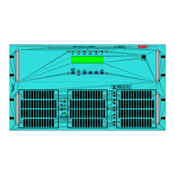
Page 25: Controls, Indicators And Connectors
HC5-10 6. Controls, Indicators and Connectors This chapter describes the front and rear panels of the HC5-10, with a brief indication of all the different components. 6.1 Front Panel [1] ESC Button to exit from a menu. [2] LOC/REM Switch to select the local or remote control modes. - Page 26 HC5-10 [17] FANS ON Yellow LED giallo, lit when enters in function the group of emergency fans caused from excess of temperature (exceeded the 45°C), unbalancement above the 200 W or post ventilation. [18] ON Green LED, lit when the hybrid coupler is sithed on.
-
Page 27: Rear Panel
HC5-10 6.2 Rear Panel [1] MAINS VDE plug for the mains power supply. [2] AUX PS Auxiliary VDE plug for the feeding of external devices (tipically an exciter). [3] MAINS FUSE Protection fuse for the input of the mains power supply (10A). -
Page 28: Connectors Description
HC5-10 6.3 Connectors Description 6.3.1 Telemetry Connector Type: DB25 Female Rej Pwr T Ana Out Unbalanced power Ch4 T Disabled Rfl Pwr T Ana Out Reflected power OC_EXC T Dig Out OC Active when interlock is active OC_SET4 T Dig Out OC... - Page 29 HC5-10 6.3.3 I C Connector Type: DB9 Female Serial Data Serial Clock 6.3.4 REM CTRL connector Type: DB9 Male 485+ 485- IN RST C (Reset Combiner Command) IN ON C (On Combiner Command) IN OFF C (Off Combiner Command) INH PJ (Amplifier’s Inhibit) EXC ON (On Exciter Command) 6.3.5 Com Bus...
-
Page 30: Technical Specifications
19.5kW; 10kW of RF output (including the exciter) in the worse situations Power consumption of PJ2000M-C without PFC 26.5kVA; 10kW of RF output (including the exciter) in the worse situations Operation limits of the combiner HC5-10 Maximum power input 250W Maximum output forward power 12.5kW Maximum output reflected power 1.8kW... -
Page 31: Electrical Description
HC5-10 8. Electrical description HC5 is composed of different modules wired between them with connectors, allowing for easy servicing or module substitution. RF output to Amp 1 RF input from exciter RF output RF Splitter to Amp 5 Telemetry, RS232, Display, Keys Interlock ... -
Page 32: Modules Identificarion (Upper View)
HC5-10 8.1 Modules Identificarion (upper view) Figure below shows the upper view of the device with the indication of the different components [1] Combiner Section [2] Power Measure Board (not visible) [3] CPU group [4] Phase Regulation Board (not visible) -
Page 33: Modules Identificarion (Bottom View)
HC5-10 8.2 Modules Identificarion (bottom view) Unbal Power card Temperature Sensor Unbal Power card Unbal Power card Unbal Power card Unbal Power card Input Splitter Circuit User Manual Rev. 1.0 - 26/03/04 29 / 34... -
Page 34: Theory Of Operation
HC5-10 9. Theory of Operation The figure shows the block diagrams of HC5-10. A general description of the machine’s operation has been given in the precedents chapters, while in this chapter comes described the operation of the various blocks. 9.1 Operating Blocks 9.1.1 Power Supply... - Page 35 HC5-10 9.1.3 Input Splitter Circuit The Power Splitter circuit mounted on the rear part of the equipment in the opposite side of the input connector to the exciter and of the RF outputs to the amplifiers. The circuit is realized with strip line plus coaxial cables.
-
Page 36: Phase Regulation Between The Several Amplifiers
The hybrid coupler is factory-adjusted so that the transmitter it is included in will work satisfyingly works over the whole FM band. Cases may happen, that it is necessary to perform the RF adjustment of the HC5-10, for example if the RF interconnection cables with the amplifiers have been sustituted with other of slightly different characteristics or length, or if it is desirable to optimize the transmitter’s performances on a certain frequency. - Page 37 HC5-10 Regulate the variable capacitors (3) and (4), related to the second amplifier so as to diminish Rej.Pwr measured from the coupler. Regulate the variable capacitors (5) and (6), related to the third amplifier so as to diminish Rej.Pwr measured from the coupler.
-
Page 38: Maintenance Procedures
10.1 Routine Maintenance The only regular maintenance needed by HC5-10, is the periodic substitution of the blowers, and the cleaning of dust filters and any dust accumulated inside the amplifier. The time between overhauling of the blowers depends upon several environmental factors, temperature, humidity, dust pollution etc.
Need help?
Do you have a question about the HC5-10 and is the answer not in the manual?
Questions and answers