
Related Manuals for TAS POWERTEK APFC-05

Summary of Contents for TAS POWERTEK APFC-05
- Page 1 Automatic Power Factor Controller APFC-05 User Manual Version 1.0 TAS POWERTEK PVT.LTD. VERSION 1.0 Updated on: FEB. 18, 2015...
- Page 2 Offenders will be liable for damages. All rights are reserved. Because of continuous improvements efforts by TAS PowerTek in their Product’s Features and Specifications, the Product as well as the content of the User Manual is likely to get updated.
-
Page 3: Table Of Contents
-- 23 to 25 Steps -- 26 & 27 Step utilization -- 28 Commissioning Instructions -- 29 & 30 Troubleshooting procedure -- 31 & 32 Manufacturer’s Contact Details -- 33 TAS POWERTEK PVT.LTD. VERSION 1.0 Updated on: FEB. 18, 2015 - 1 -... -
Page 4: Features
• Standard 96x96 mm Plastic Cabinet for panel door flush mounting. • Protections provided: Over/Under Voltage Over / Under load current Over Temperature internal to APFC-05 Unit All these are user settable TAS POWERTEK PVT.LTD. VERSION 1.0 Updated on: FEB. 18, 2015 - 2 -... -
Page 5: Specifications
All Dimensions given are in mm. Recommended size for cut-out on panel door is 92 x 92 mm. Max. weight: (with clamps and terminals) = Approx. 0.6 Kgs. TAS POWERTEK PVT.LTD. VERSION 1.0 Updated on: FEB. 18, 2015 - 3 -... -
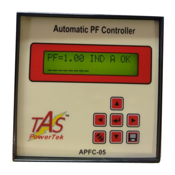
Page 6: Front Fascia
Front fascia Keyboard, LCD display LCD Display LCD Display Contrast Adjustment Slot for small Allen-Key, at the Top Surface PF=0.98 IND A OK Key pad TAS POWERTEK PVT.LTD. VERSION 1.0 Updated on: FEB. 18, 2015 - 4 -... -
Page 7: Back Side Terminals
BACK SIDE TERMINALS •Auxiliary & Measurement Voltage Load Current CT Output Terminals TAS POWERTEK PVT.LTD. VERSION 1.0 Updated on: FEB. 18, 2015... -
Page 8: Pf Correction Technique -- 6
Capacitor addition band. Capacitor removal band. Case-2: PF-UPPER as Capacitive & PF-LOWER set as Inductive: kVAr (Ind) smallest Capacitor bank kVAr x 2 width. LOWER. LOWER. UPPER. UPPER. kVAr (Cap) TAS POWERTEK PVT.LTD. VERSION 1.0 Updated on: FEB. 18, 2015 - 6-... - Page 9 PF relays. The settings like C/K ratio and kVAr offsets/shifts are eliminated which makes APFC-05 user friendly and thus easy to commission. TAS POWERTEK PVT.LTD. VERSION 1.0 Updated on: FEB. 18, 2015 - 7 -...
-
Page 10: Typical Wiring Scheme -- 8
Power factor on secondary side of the transformer. This scheme is preferred with LT consumers of electricity, where the metering is carried out on LT side. TAS POWERTEK PVT.LTD. VERSION 1.0 Updated on: FEB. 18, 2015 - 8-... - Page 11 HT side. This scheme gives the compensation against magnetizing current of the transformer. Thus, for HT metering able to give more accurate results. TAS POWERTEK PVT.LTD. VERSION 1.0 Updated on: FEB. 18, 2015 - 9 -...
-
Page 12: Control Wiring Scheme
Control wiring diagram Load Current APFC-05 Either of the above specified schemes can be selected by the user based on the system requirement. TAS POWERTEK PVT.LTD. VERSION 1.0 Updated on: FEB. 18, 2015 - 10 -... -
Page 13: Rear Side Terminals
Output commands to capacitor contactors APFC 05 COM = common, C1…… C8 = potential free relays, maximum of up to 8 Stages, 0.5A, 230Vac, Inductive Load. F2 Fast-Blow Fuse Protected. TAS POWERTEK PVT.LTD. VERSION 1.0 Updated on: FEB. 18, 2015 - 11 -... -
Page 14: Front Fascia Lcd Screen Details -- 12
FIXED & is in ON state. bank is declared FAULTY & not available for use output stage is not used in the system. bank is in DISCHARGE mode (blinking red LED) TAS POWERTEK PVT.LTD. VERSION 1.0 Updated on: FEB. 18, 2015 - 12 -... - Page 15 Bank no. 5 is in discharging state. Bank nos.6 and 7 are in off state. Ready to be switched on. Bank (output) no. 8 is not used / not connected. TAS POWERTEK PVT.LTD. VERSION 1.0 Updated on: FEB. 18, 2015...
-
Page 16: Keyboard Details
PROGRAM key. Used for selecting modes of operation and editing of parameters MEMORY key. Used to save all changes made in Edit Parameters menu. TAS POWERTEK PVT.LTD. VERSION 1.0 Updated on: FEB. 18, 2015 - 14 -... -
Page 17: Display Of Various Parameters
Displays the measured kVAr value Display of each connected output step. Step kVAr Display Displays the internal (cabined) temperature. Aux-Function TAS PowerTek India Displays the version of software. APFC 05 TAS POWERTEK PVT.LTD. VERSION 1.0 Updated on: FEB. 18, 2015 - 15 -... -
Page 18: Sub Menu For Display Of Parameters
Sub menu for display of parameters continued.. TAS POWERTEK PVT.LTD. VERSION 1.0 Updated on: FEB. 18, 2015 - 16 -... -
Page 19: Method Of Keyboard / Display Usage -- 17 To
Disable Option is Enable/Disable. Default Enter Password: Display mode **** PRESS Enter the 4 digit Password by using & keys. PRESS PASSWORD Correct? Continued on next page TAS POWERTEK PVT.LTD. VERSION 1.0 Updated on: FEB. 18, 2015 -17 –... - Page 20 1 2 3 4 5 6 7 8 9 10 11 12 13 14 15 16 Default Display mode Select 1. Edit Parameter Select 2. Auto Operation Select 3. Manual Operation Continued on next page TAS POWERTEK PVT.LTD. VERSION 1.0 Updated on: FEB. 18, 2015 - 18 -...
- Page 21 Grid / transformer / APFC System system related parameters Edit Parameters Fault trip settings Fault Edit Parameters Capacitor bank step settings Step Edit Parameters Banks utilization counter Utilization Cntr TAS POWERTEK PVT.LTD. VERSION 1.0 Updated on: FEB. 18, 2015 - 19 -...
-
Page 22: Keyboard / Display Operations -- 20
Power down, the status is unchanged), press MEMORY key. After saving the settings, the unit will jump back to default mode. (Default as Auto or Manual is set in Edit Parameters). continued.. TAS POWERTEK PVT.LTD. VERSION 1.0 Updated on: FEB. 18, 2015 - 20 -... -
Page 23: Edit Parameters
Note: In the Edit Parameters area, if no keys are pressed for more than a minute, the default display screen comes on and the changes done till that time are discarded. TAS POWERTEK PVT.LTD. VERSION 1.0 Updated on: FEB. 18, 2015... -
Page 24: General & Io
Reading to a Positive Value to indicate Energy Auto kW Polr Chk “Import” without reversing the CT Polarity in case Disable: 0 the kW reading is a –Ve value. continued.. TAS POWERTEK PVT.LTD. VERSION 1.0 Updated on: FEB. 18, 2015 - 22 -... - Page 25 Under-Load KW can be calculated as shown here. Over load Resume :125% Under load flt Disable Under load Limit :020% Under load Resume :025% continued.. TAS POWERTEK PVT.LTD. VERSION 1.0 Updated on: FEB. 18, 2015 - 23 -...
- Page 26 )} + tan{cos UPPER LOWER For PF Capacitive and PF Capacitive: UPPER LOWER 1.25 x Smallest bank kVAr. Under-Load kW value setting = )} – tan{cos [tan{cos UPPER LOWER TAS POWERTEK PVT.LTD. VERSION 1.0 Updated on: FEB. 18, 2015 - 24 -...
-
Page 27: Fault -- 23 To
This is when Bank KVAR Fault the step is put in the tolerance limit defined here is Tolerance exceeded, that specific bank is declared faulty. Bank KW Fault Tolerance TAS POWERTEK PVT.LTD. VERSION 1.0 Updated on: FEB. 18, 2015 - 25 -... -
Page 28: Steps -- 26
Digits can be 1,2,-- 9, Unequal Bank [5] KVAr = 050 Unequal Bank [6] KVAr = 050 Unequal Bank [7] KVAr] = 050 Unequal Bank [8] continued.. KVar = 050 TAS POWERTEK PVT.LTD. VERSION 1.0 Updated on: FEB. 18, 2015 - 26 -... - Page 29 (at defined Capacitor Bank Voltage). APFC-05 has a in built intelligent algorithm to select the best possible combination to suit the exact kVAr requirement for compensation. TAS POWERTEK PVT.LTD. VERSION 1.0 Updated on: FEB. 18, 2015 - 27 -...
-
Page 30: Step Utilization
Yes and pressing save command will reset the specific bank utilization counter to zero. This is normally done in case the specific bank is replaced with the new one. TAS POWERTEK PVT.LTD. VERSION 1.0 Updated on: FEB. 18, 2015 - 28 -... -
Page 31: Commissioning Instructions -- 29
Loose connection or open CT secondary can result in very high voltages getting developed in the circuit which can damage the CT and also produce high levels of noise in the system. TAS POWERTEK PVT.LTD. VERSION 1.0 Updated on: FEB. 18, 2015... - Page 32 Switch Off the supply to panel and put it ON. APFC-05 will first turn ON all the capacitor banks and turn them off. Observe panel performance for about 2 Hours after commissioning TAS POWERTEK PVT.LTD. VERSION 1.0 Updated on: FEB. 18, 2015...
-
Page 33: Troubleshooting Procedure -- 31
Capacitor current and fluctuating. higher level of THD can cause some errors in individual step kVAr measurement. Under this condition, best is to keep this feature disabled. continued.. TAS POWERTEK PVT.LTD. VERSION 1.0 Updated on: FEB. 18, 2015 - 31 -... - Page 34 MOVs for AC Circuits Snubbers or MOVs / or free-wheeling free-wheeling diodes, diodes for DC Circuits across the Contactor are not put with Coils is mandatory. contactor coils. TAS POWERTEK PVT.LTD. VERSION 1.0 Updated on: FEB. 18, 2015 - 32 -...
-
Page 35: Manufacturer's Contact Details
Weekly Off: Saturdays. E-mail: sales@taspowertek.com Web: www.taspowertek.com This Product is completely Designed, Developed, Manufactured,Assembled, Tested, and Calibrated in India by TAS PowerTek Pvt. Ltd., Nasik – 422 010, India. - 33 - TAS POWERTEK PVT.LTD. VERSION 1.0 Updated on: FEB. 18, 2015...
Need help?
Do you have a question about the POWERTEK APFC-05 and is the answer not in the manual?
Questions and answers