
Subscribe to Our Youtube Channel
Related Manuals for TAS APFC-06 04

Summary of Contents for TAS APFC-06 04
- Page 1 Automatic Power Factor Controller for L.T. Applications APFC-06/xx xx =04/06/08/12 Relay Output Channels User Manual First Release Date: 16 April 2018. Updated on: 17 February. 2022.
- Page 2 Should further information be desired or should particular problems arise which are not covered sufficiently for the purchasers purposes, the matter should be referred to TAS office. The contents of this instruction Manual shall not become part of or modify any prior or existing agreement or relationship.
- Page 3 Power Factor Controller APFC 06 Index Index page -- 1 Features -- 2 Specifications -- 3 Mechanical dimensions -- 4 Front fascia -- 5 Rear side terminals -- 6 PF correction technique -- 7 & 8 Typical wiring scheme -- 9 Control wiring scheme -- 10 Front fascia LCD screen details...
- Page 4 Power Factor Controller APFC 06 Features: • 32-Bit ARM Cortex-Mx State-of-the-Art Technology Micro-Controller controlled Digital Signal Processing logic for measurements, monitoring, indication, alarming & controls. Power Measurements with Class-3 accuracy as IEC62053- • pt21 & 23. Auto CT polarity check (user editable) Phase-to-Phase Measurement Voltage Feedback on •...
-
Page 5: Specifications
Power Factor Controller APFC 06 Specifications: • Feed-back Voltage: 1-Ph, 2-wire (Phase-to-Phase), Nom. 415 Volts. (User Settable Range: 110 to 480 Vac, in step of 1 Volt). • Supply Current Feedback (CT) I/P: Selectable Nom. 1 Amp or 5 Amp. •... -
Page 6: Mechanical Dimensions
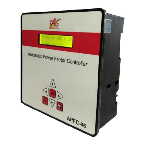
Power Factor Controller APFC 06 Mechanical dimensions: All Dimensions are in mm. Recommended size for cutout on panel door: 138 mm x 138 mm. Maximum weight: (with mounting clamps) = 0.8 kg approx. Note: Low-Depth behind the APFC Panel Door, being a slim model! - 4 -... - Page 7 Power Factor Controller APFC 06 Front fascia: Keyboard, LCD Display LCD Display with LED Back-Light having Auto-On/Off PF= 1.00 IND A OK PF= 1.00 IND A OK 7-Keys Key-pad - 5-...
- Page 8 Power Factor Controller SPF Supply current Rear side terminals Feedback CT, User Selection of Auxiliary Digital Outputs – 1 Amp or 5 Amp Potential-free, N.O. Relay Contact, Nominal & Contact Rating: 5A (Resistive), 240Vac nominal Common APFC - 06 Auxiliary Digital Measurement Input,...
-
Page 9: Pf Correction Technique
Power Factor Controller APFC 06 PF correction technique Case-1: PF & PF both set as inductive: UPPER LOWER LOWER. LOWER. kVAr (Ind) smallest Capacitor bank kVAr x 1.5 width. UPPER. UPPER. kVAr (Cap) No change band. Capacitor addition band. Capacitor removal band. Case-2: PF as Capacitive &... - Page 10 Power Factor Controller APFC 06 Case-3: PF & PF- both set as Capacitive: UPPER LOWER kVAr (Ind) smallest Capacitor bank kVAr x 1.5 width. LOWER. LOWER. UPPER. UPPER. kVAr (Cap) No change band. Capacitor addition band. Capacitor removal band. There are two PF set points to be set in APFC 06. The UPPER limit and the LOWER limit.
- Page 11 Power Factor Controller APFC 06 Typical wiring diagram for PF correction Load CT H.T. side L.T. side Conventional L.T. side PF improvement system schematic As per this scheme, the Supply (Load) Current sensing CT is put between the source and the PF correction capacitor banks.
-
Page 12: Control Wiring Diagram
Power Factor Controller APFC 06 Control wiring diagram : Quadrature Mode Connection : Use any two phases for voltage monitoring and use the third phase for the current monitoring. Aux. Input supply Fuse 3.0 A, Fuse 0.5 A, Fuse 5.0 A, Fast Blow Slow Blow Fast Blow... -
Page 13: Front Fascia
Power Factor Controller APFC 06 Front fascia: LCD screen, LED indications PF=1.00 IND A OK First line of display indicates the PF value, inductive / capacitive PF, mode of operation and fault / OK status: “PF = 1.00” indicates the overall PF of the system. “IND”... -
Page 14: Lcd Display Screen
Power Factor Controller APFC 06 Front fascia: LCD Display Screen Example of a typical LCD display screen is show below: PF=0.98 IND A OK Meaning of this screen contents: Total no. of banks connected is seven. Power Factor at load sensing CT is 0.98 ‘IND’ Inductive. (‘CAP’ defines Capacitive). - Page 15 Power Factor Controller APFC 06 Front fascia: Keyboard Keyboard with soft touch keys are provided on the front facia of the controller. The various keys are: ▲ key. Used to scroll up the menu screen; increment values when entering numbers. Also used for changing the status of banks.
- Page 16 Display Displays the internal (cabinet) temperature. Aux-Function Displays the Firmware version in APFC Controller. This can change as TAS POWERTEK and when found necessary. Therefore, always refer to the latest Ver. 2.1.1 one and with corresponding User Manual. - 14 -...
-
Page 17: Sub-Menu For Display Of Parameters
Power Factor Controller APFC 06 Sub-menu for display of parameters Harmonics Power Harmonics Overall Values V-THD -F Mains Voltage I-THD -F OO3.7% 000250.0 00415.6V(L-L) OOO.O% V Harmonics KVAR I Harmonics Mains Current O3rd: O2.7% 000005.7 00002.5 A O3rd: OO.O% V Harmonics I Harmonics Power Factor O5th: OO.8%... -
Page 18: Enter Password
Power Factor Controller APFC 06 Method for keyboard / display usage Flowchart for entering into different modes: PRESS If Password Enable Disable Option is Enable/Disable. Default Enter Password: Display mode **** PRESS Enter the 4 digit Password by using & keys. - Page 19 Power Factor Controller APFC 06 1 2 3 4 5 6 7 8 9 10 11 12 13 14 15 16 Default Display mode Select 1. Edit Parameter Select 2. Auto Operation Select 3. Manual Operation Continued on next page - 17 -...
- Page 20 Power Factor Controller APFC 06 Select Select Select 1. Edit Parameter 2. Auto Operation 3. Manual Operation PF=0.98 IND A OK PF=0.98 IND M OK Operation in Auto Operation in Manual Mode. Mode. Edit Parameters Edit Parameters General parameters General and IO Edit Parameters Grid / transformer / APFC System...
- Page 21 Power Factor Controller APFC 06 Keyboard / Display operations Mode Selection There are two modes of operation (Manual and Auto) and one mode for APFC system entry (Edit Parameters). Press the Triple▼(Mode/Program) key. Enter password (if enabled) by using ◄►▲▼ keys. Press ↵. Now using ▲▼ keys, select the Mode of operation: •...
- Page 22 Power Factor Controller APFC 06 …continued. For Testing banks with manual ON / OFF commands: Press ENTER key, the cursor will start blinking. Use ◄► keys to select the specific bank/s that are healthy and use ▲ key to turn ON and use ▼ key to turn OFF that capacitor banks. To come out of Manual ON/OFF edit mode, press ↵...
- Page 23 Power Factor Controller APFC 06 General & IO Password: Enable or disable password. PASSWORD Value: 0=Disable, 1=Enable. Enable Change Password: Set new value of password (4 CHANGE PASSWORD digit). Factory default password is “0000” : 0001 Load Default: Loads factory set default parameters. LOAD DEFAULT 0=No, 1=Yes.
- Page 24 Power Factor Controller APFC 06 Fault For most of the types of faults defined here, the options Over voltage flt available are as hereunder: Off Step 0=Disable Over voltage 1=Indicate (Display a Fault Message & or store in Flash) Limit ( % ) :115 Over voltage 2=Off Step (Switch off Non Fixed Steps one by one)
- Page 25 Power Factor Controller APFC 06 kVAr (Ind) Under Load settings: LOWER. 1.5 x smallest UPPER. Capacitor bank Under- Load. No change band. Capacitor Addition band. Capacitor Addition band. kVAr kVAr (Cap) Capacitor Removal band. For PF Inductive and PF Inductive : UPPER LOWER 1.5 x Smallest Capacitor Bank kVAr.
- Page 26 Power Factor Controller APFC 06 Internal Temperature Fault: Unit monitors Int Temperature Flt temperature inside APFC housing. This Disable temperature can go up either due to ambient temperature Temperature in the APFC panel has gone up beyond limit or if some Resume : 55 Deg C component failure in APFC 06 hardware itself.
- Page 27 Power Factor Controller APFC 06 Capacitor Bank Steps: Steps Connected: Defines the number of steps Steps connected operational. Depending on PF system banks, this : 12 parameter is set. Default mode • Default Mode: 0: Auto and 1: Manual. This parameter Auto defines the mode during Power up.
- Page 28 Power Factor Controller APFC 06 • C Series: Various control series (C Series) can be selected 00: 1 1 1 1 1 1 1 1 1 1 1 1 1 1 1 1. 01: 1 2 2 2 2 2 2 2 2 2 2 2 2 2 2 2. 02: 1 2 3 3 3 3 3 3 3 3 3 3 3 3 3 3.
- Page 29 Power Factor Controller APFC 06 Utilization Cntr (Counters): Utilization cntr: Bank nn: This gives the number of ON/OFF operations of the “nn”th bank. • Reset Utilization Counter - Bank nn: Options are “Yes” and “No”. Declaring specific bank no with Yes and pressing save command will reset the specific bank utilization counter to zero.
-
Page 30: Commissioning Instructions
Power Factor Controller APFC 06 Commissioning Instructions Before panel is powered up for the first time 1. Panel Wiring Check Ensure that all connections in the panel is tightened properly and there are no loose connections. Also ensure that the wiring is done as per the wiring diagram. - Page 31 Power Factor Controller APFC 06 After panel is powered up 1. Remove the fuses/switch off MCBs/MCCBs which are in series with every capacitor bank. Connect supply to the APFC-06 . Keep the load feedback current feedback in shorted condition 2. Turn ON the supply to the panel and set the various parameters as per the panel configuration.
-
Page 32: Troubleshooting Procedure
Power Factor Controller APFC 06 Troubleshooting procedure Nature of Fault Probable Reason Action to be taken Unit does not turn •Input auxiliary supply •Check the input supply not coming. & restore. •Input side fuse •Check input side fuses (external)blown (external) OK. Unit does not turn The load kW is too •... - Page 33 Power Factor Controller APFC 06 EDIT PARAMETERS : MINIMUM , MAXIMUM AND DEFAULT VALUES INCREMENT / PARAMETER FACTORY DECREMENT DEFAULT STEP SIZE GENERAL and IO 1] Password (Enable: 1/ Disable: 0) 2] Change Password 0000 9999 0001 3] Load Default (Yes: 1/ No: 0) 4] THD to display (F-THD: 1/R-THD: 0) 5] Unit ID...
- Page 34 Power Factor Controller APFC 06 EDIT PARAMETERS : MINIMUM , MAXIMUM AND DEFAULT VALUES INCREMENT / PARAMETER FACTORY DECREMENT DEFAULT STEP SIZE FAULTS 1] Over Voltage Fault Disable: 0 Indicate: 1 Off Step: 2 Off Fixed : 3 Fast Off : 4 Set Resume 2] Over Voltage Limit (%) Limit...
- Page 35 Power Factor Controller APFC 06 EDIT PARAMETERS : MINIMUM , MAXIMUM AND DEFAULT VALUES INCREMENT / PARAMETER FACTORY DECREMENT DEFAULT STEP SIZE FAULTS 13] Temperature Fault (Internal to APFC Unit) Disable: 0 Indicate: 1 Off Step: 2 Off Fixed : 3 Fast Off : 4 14] Temperature Resume (Deg.
- Page 36 Power Factor Controller APFC 06 EDIT PARAMETERS : MINIMUM , MAXIMUM AND DEFAULT VALUES PARAMETER STEP FACTORY SIZE DEFAULT STEPS 1] Steps Connected, as per ordered Model 04 / 06 / 08 / 12 As per Ordered. 2] Default Mode (Auto: 0/ Manual:1) 3] Compensation kVAr (Instant: 0/ Mean: 1)
- Page 37 Power Factor Controller APFC 06 EDIT PARAMETERS : MINIMUM , MAXIMUM AND DEFAULT VALUES STEP FACTORY PARAMETER SIZE DEFAULT UTILIZATION COUNTERS 1] Utilization counter Bank [1] (not editable) 000000 999999 2] Utilization counter Bank [2] (not editable) 000000 999999 3] Utilization counter Bank [3] (not editable) 000000 999999 4] Utilization counter Bank [4] (not editable)
- Page 38 Power Factor Controller APFC 06 Blank Forms for Field User Entries FORM - I PARAMETER As On As On As On As On Date Date Date Date GENERAL and IO 1] Password (Enable: 1/ Disable: 0) 2] Change Password 3] Load Default (Yes: 1/ No: 0) 4] THD to display (F-THD: 1/R-THD: 0) 5] Unit ID...
- Page 39 Power Factor Controller APFC 06 Blank Forms for Field User Entries FORM - I PARAMETER As On As On As On As On Date Date Date Date FAULTS 1] Over Voltage Fault Disable: 0 Indicate: 1 Off Step: 2 Off Fixed : 3 Fast Off : 4 2] Over Voltage Limit (%) 3] Over Voltage Resume (%)
- Page 40 Power Factor Controller APFC 06 Blank Forms for Field User Entries FORM - I PARAMETER As On As On As On As On Date Date Date Date FAULTS 13] Temperature Fault Disable: 0 Indicate: 1 Off Step: 2 Off Fixed : 3 Fast Off : 4 14] Temperature Resume 15] Temperature Limit...
- Page 41 Power Factor Controller APFC 06 Blank Forms for Field User Entries FORM - I PARAMETER As On As On Date As On Date As On Date Date STEPS 1] Steps Connected 2] Default Mode (Auto: 0/ Manual:1) 3] Compensation kVAr (Instant: 0/ Mean: 1) 4] Cap Bank Voltage (L-L) 5] Correction Time (Seconds)
- Page 42 Power Factor Controller APFC 06 Blank Forms for Field User Entries FORM - I As On As On Date PARAMETER As On As On Date Date Date UTILIZATION COUNTERS 1] Utilization counter Bank [1] (not editable) 2] Utilization counter Bank [2] (not editable) 3] Utilization counter Bank [3] (not editable) 4] Utilization counter Bank [4] (not editable) 5] Utilization counter Bank [5] (not editable)
- Page 43 Power Factor Controller APFC 06 Contact us: The Sales & Marketing / The Customer Support & Service Dept., TAS PowerTek Ltd., W-61, C/o. Pawar Industries, Opp. “Machine House”, MIDC Industrial Area, Ambad, Nasik – 422 010 (via Mumbai), Maharashtra State, India.
Need help?
Do you have a question about the APFC-06 04 and is the answer not in the manual?
Questions and answers