Table of Contents
Advertisement
Quick Links
Advertisement
Table of Contents

Related Manuals for Shuttle AV11


Summary of Contents for Shuttle AV11
- Page 1 AV11 PPGA Celeron processor Based AGP MAIN BOARD User's Manual...
- Page 2 Shuttle Inc. Disclaimer Shuttle Inc. shall not be liable for any incidental or consequential damages resulting from the performance or use of this product. This company makes no representations or warranties regarding the contents of this manual.
-
Page 3: Table Of Contents
2 FEATURES..................7 2.1 SPECIFICATIONS ..................7 3 HARDWARE INSTALLATION............10 3.1 STEP BY STEP INSTALLATION..............1 0 Accessories Of AV11 ................10 STEP 1 Install the CPU ................11 STEP 2 Set Jumpers ................12 STEP 3 Install SDRAM System Memory ..........12 STEP 4 Install Internal Peripherals in System Case ....... - Page 4 STEP 11 Connect External Peripherals to Back Panel......19 STEP 12 First Time System Boot Up ............20 STEP 13 Install Drivers & Software Components ........21 3.2 JUMPER SETTINGS ................... 2 2 Jumpers & Connectors Guide ..............23 Set Keyboard & PS/2 Mouse Power-On (JP3)........25 CPU Host Frequency Setting (JP8) ............
- Page 5 3.3 SYSTEM MEMORY CONFIGURATION ............35 Install Memory..................35 Upgrade Memory ..................35 4 SOFTWARE UTILITY ..............36 4.1 AV11 MAINBOARD CD OVERVIEW............36 4.2 INSTALL MAINBOARD DRIVER............... 3 7 4.3 TO VIEW THE USER'S MANUAL..............38 5 BIOS SETUP ................39 5.1 ENTERING BIOS..................3 9 5.2 THE MAIN MENU..................
-
Page 6: What's In The Manual
BIOS Setup >> How to Configure............Page 39 About This Manual For First-Time DIY System Builder............Page 5 For Experienced DIY User...............Page 5 For System Integrator................P age 5 Technical Support Contact Your Dealer Shuttle’s (RMA or Warranty) Policy - 4 -... -
Page 7: Introduction
Experienced DIY User Congratulations on your purchase of the Shuttle AV11 mainboard. You will find that installing your new Shuttle AV11 mainboard is just that easy. Bundled with an array of onboard functions, the highly-integrated AV11 mainboard provides you with a total solution to build the most stable and reliable system. -
Page 8: Item Checklist
1.2 Item Checklist Check all items you received with your AV11 mainboard to make sure nothing is missing. The complete package should include: One Shuttle AV11 Mainboard (with onboard Socket 370, built-in VIA693A chipset, ATX form factor, including 2xUSB, 2xSerial, and 1xParallel ports, plus 1xPS/2 Keyboard, and 1xPS/2 Mouse connectors.) -
Page 9: Features
2 FEATURES The AV11 mainboard is carefully designed for the demanding PC user who wants high performance and maximum intelligent features in a compact package. 2.1 Specifications CPU Support Support Intel PPGA Celeron 300 ~ 500+ MHz Chipset Features VIA VT82C693A AGPset with I/O subsystems. - Page 10 2 × USB connectors 2 × DB9 Serial connectors 16550 UART compatible 1 × Infrared communications port ASKIR and HPSIR compatible. (Serial port COM2 can also be redirected to an external IrDA Adapter for wireless connection.) 1 × DB25 Parallel port supporting Standard Parallel Port (SPP), Enhanced Parallel Port (EPP), and Extended Capabilities Port (ECP) data transmission schemes.
- Page 11 Advanced Features Dual Function Power Button - The system can be in one of two states, one is Suspend mode and the other is Soft-Off mode. Pushing the power button for less than 4 seconds places the system into Suspend mode. When the power button is pressed for longer than 4 seconds, the system enters the Soft-Off mode.
-
Page 12: Hardware Installation
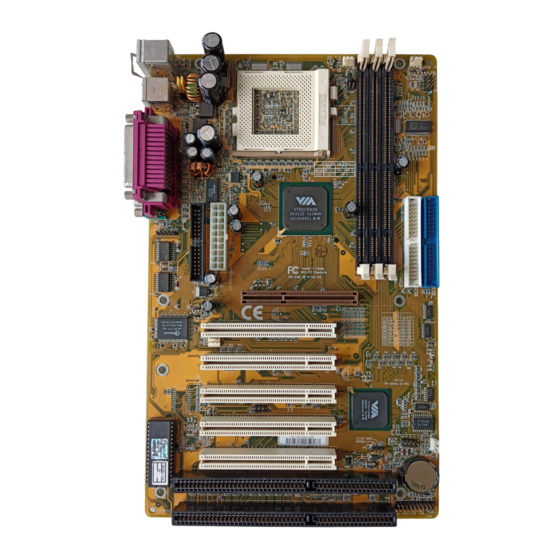
3 HARDWARE INSTALLATION This section outlines how to install and configure your AV11 mainboard. Refer to the following mainboard layout to help you identify various jumpers, connectors, slots, and ports. Then follow these steps designed to guide you through a quick and correct instal- lation of your system. -
Page 13: Step 1 Install The Cpu
Step 1 Install the CPU: 1. Locate the CPU ZIF (Zero Insertion Force) socket on the upper-right sector of your mainboard (between the back-panel connectors and the DIMM memory banks). 2. Pull the CPU ZIF socket lever slightly sideways away from the socket to unlock the lever, then bring it to an upward vertical position. -
Page 14: Step 2 Set Jumpers
Step 2. Set Jumpers This mainboard is jumperless! The default jumper settings have been set for the common usage standard of this mainboard. Therefore, you do not need to reset the jumpers unless you require special adjustments as in any of the following cases: 1. -
Page 15: Step 4 Install Internal Peripherals In System Case
Step 4 Install Internal Peripherals in System Case Before you install and connect the mainboard into your system case, we recommend that you first assemble all the internal peripheral devices into the computer housing, including but not limited to the hard disk drive (IDE/ HDD), floppy disk drive (FDD), CD-ROM drive, and ATX power supply unit. -
Page 16: Step 5 Mount The Mainboard On The Computer Chassis
Step 5 Mount the Mainboard on the Computer Chassis 1. You may find that there are a lot of different mounting hole positions both on your computer chassis and on the mainboard. To choose a correct mounting hole, the key point is to keep the back-panel of the mainboard in a close fit with your system case, as shown below. -
Page 17: Step 6 Connect Front Panel Switches/Leds/Speaker
Step 6 Connect Front Panel Switches/LEDs/Speaker You can find there are several different cables already existing in the system case and originating from the computer’s front-panel devices (HDD LED, Power LED, Reset Switch, PC Speaker, etc.) These cables serve to connect the front-panel switches and LEDs to the mainboard’s front-panel connectors group, as shown below. - Page 18 4. HDD-LED (HDLED) 5. Power-LED (PW LED) 6. Hardware Reset Switch (RST) 7. PC Speaker (SPK) - 16 -...
-
Page 19: Step 7 Connect Ide & Floppy Disk Drives
Step 7 Connect IDE & Floppy Disk Drives 1. IDE cable connector 2. FDD cable connector Step 8 Connect Other Internal Peripherals 1. IR connector - 17 -... -
Page 20: Step 9 Connect The Power Supply
Step 9 Connect the Power Supply 1. System power connector Step 10 Install Add-on Cards in Expansion Slots 1. Accelerated Graphics Port (AGP) Card 2. PCI Card 3. ISA Card - 18 -... -
Page 21: Step 11 Connect External Peripherals To Back Panel
Step 11 Connect External Peripherals to Back Panel You are now ready to put the computer case back together and get on to the external peripherals connections to your system’s back-panel. 1. PS/2 Mouse and Keyboard PS/2 Mouse PS/2 keyboard 2. -
Page 22: Step 12 First Time System Boot Up
Step 12 First Time System Boot Up To assure the completeness and correctness of your system installation, you may check the above installation steps once again before you boot up your system for the first time. 1. Insert a bootable system floppy disk (DOS 6.2x, Windows 95/98/NT, or others) which contains FDISK and FORMAT utilities into the FDD. -
Page 23: Step 13 Install Drivers & Software Components
Make sure your Windows 9x operating system is already installed before running the drivers installation CD-ROM programs. 1. Insert the AV11 bundled CD-ROM into your CD-ROM drive. The auto-run program will display the drivers main installation window on screen. -
Page 24: Jumper Settings
3.2 Jumper Settings Several hardware settings are made through the use of jumper caps to connect jumper pins on the mainboard. Pin #1 is located on the bottom or on the left when holding the mainboard with the keyboard connector or other back-panel connectors opposite from you, as shown below. -
Page 25: Jumpers & Connectors Guide
Jumpers & Connectors Guide Use the mainboard layout on page 10 to locate CPU socket, memory banks, expansion slots, jumpers and connectors on the mainboard during the installation. The following list will help you identify jumpers, slots, and connectors along with their assigned functions: CPU/Memory/Expansion Slots Socket370: CPU Socket for PGA 370 Celeron processors DIM4/5/6 : Three DIMM Sockets for 8,16,32,64,128,256MB 3.3V... - Page 26 Back Panel Connectors : PS/2 Keyboard : PS/2 Mouse : 2 × USB (Universal Serial Bus) COM1 : Serial Port 1 (DB9 male) COM2 : Serial Port 2 (DB9 male) PRINTER : Parallel Port (DB25 female) Front Panel Connectors (JP13) PWON : ATX Power On/Off Momentary Type Switch GLED...
-
Page 27: Set Keyboard & Ps/2 Mouse Power-On (Jp3)
Set Keyboard & PS/2 Mouse Power-On (JP3) AV11 mainboard provides an easy power-on by keyboard and PS/2 mouse. Note: When you enable Keyboard Power-On, you also need to configure the proper hot-key combination <Ctrl> + < function key F1 ~ F12 >... -
Page 28: Cpu Host Frequency Setting (Jp8)
Intel Celeron CPU specification. We strongly advise novice users not to modify the original setting of the CPU host frequency, for setting an incor- rect value may damage your CPU. For experienced users, the AV11 mainboard provides an alternative Hard- Configure function to adjust your CPU host frequency manually. Note:... -
Page 29: Cpu Clock Ratio Setting (Jp9)
CPU Clock Ratio Setting (JP9) AV11 mainboard provides a jumper group JP9 to set CPU speed configure by BIOS or by hardware jumper. By inserting jumper pack on Manual group properly, the user can configure the CPU Clock Ration manually. -
Page 30: Clear Cmos (Jp12)
Clear CMOS (JP12) JP12 is used to clear CMOS data. Clearing CMOS will result in perma- nently erasing the previous system configuration settings and restoring the original (factory-set) system settings. Pin 1-2 (Default) Pin 2-3 (Clear CMOS) Step 1. Turn off the system power (PC-> Off) Step 2. -
Page 31: Usb1/Usb2 Port Connectors
USB1/USB2 Port Connectors Two female connectors USB1/USB2 share the same USB (Universal Serial Bus) bracket at the rear panel of your mainboard. Plug each USB device jack USB1 & USB2 into an available USB1/USB2 connector. COM1 / COM2 Connector This mainboard can accommodate two serial device on COM1/COM2 . -
Page 32: Green Led Connector (Gled)
Green LED Connector (GLED ) The Green LED (GLED) indicates that the system is currently in one of the power savings mode (Doze/Standby/Suspend). When the system resumes to normal operation, mode, the Green LED will go off. Attach a 2-pin Green LED cable to GLED header. -
Page 33: Hardware Reset Connector (Rst)
4-pin speaker connector (SPK). Enhanced IDE Ports and Floppy Connectors The AV11 mainboard features two 40-pin dual-channel IDE device connec- tors (IDE1/IDE2) providing support for up to four IDE devices, such as CD- ROM and Hard Disk Drives (H.D.D.). This mainboard also includes one 34-pin floppy disk controller (FDC) to accommodate the Floppy Disk Drive (F.D.D.). -
Page 34: Atx Power Supply Connector (J5)
ATX Power Supply Connector (J5) Locate the 20-pin male header ATX power connector (J5) on your mainboard. Plug the power cable from the ATX power supply unit directly into J5 ATX power supply connector. Note 1: The ATX power connector is directional and will not go in unless the guides match perfectly making sure that pin#1 is properly positioned. -
Page 35: Ir Connector (J4)
IR Connector (J4) If you have an Infrared device, this mainboard can implement IR transfer function. To enable the IR transfer function, follow these steps: IR Pin Assignments: 1=VCC 2=VCC 3=IRRX 4=GND 5=IRTX Step 1. Attach the 5-pin infrared device cable to J4 connector. (Refer to the above diagram for IR pin assignment.) Step 2. -
Page 36: Sb-Link Connector (Jp10)
SB-Link Connector (JP10) The main board provides a 2x3 pin SB- Link header accepts the Creative CT4600 series PCI sound cards with PCI solution to connect the legacy Sound Blaster com- patible audio to the PCI bus. SB-Link Pin Assignments: 1=GNT#A 2=GND 3=Empty... -
Page 37: System Memory Configuration
3.3 System Memory Configuration The AV11 mainboard has three 168-pin DIMM sockets that allow you to install from 16MB up to 768MB of system memory with PC66/100/133 SDRAM (Synchronous DRAM). Each DIMM (Dual In-line Memory Module) socket can accommodate 16MB, 32MB, 64MB, 128MB, and 256MB 3.3V single or double side SDRAM modules. -
Page 38: Software Utility
Install Mainboard Software - Installing Mainboard Drivers for Windows Manual - AV11 series mainboard user's manual in PDF format. Link to Shuttle Homepage - Link to shuttle website homepage. Browse this CD - Allows you to see the contents of this CD. -
Page 39: Install Mainboard Driver
Insert the attachment CD into your CD-ROM drive and the CD AutoRun screen should appear. If the AutoRun screen does not appear, double click on Autorun icon in My Computer to bring up Shuttle Mainboard Software Setup screen. Select using your pointing device (e.g. mouse) on the “Install Mainboard Software”... -
Page 40: To View The User's Manual
Insert the attachment CD into your CD-ROM drive and the CD AutoRun screen should appear. If the AutoRun screen does not appear, double click on Autorun icon in My Computer to bring up Shuttle Mainboard Software Setup screen. Select using your pointing device (e.g. mouse) on the “Manual” bar. -
Page 41: Bios Setup
5 BIOS SETUP AV11 BIOS ROM has a built-in Setup program that allows users to modify the basic system configuration. This information is stored in battery-backed RAM so that it retains the Setup information even if the system power is turned off. -
Page 42: The Main Menu
5.2 The Main Menu Once you enter the AwardBIOS(tm) CMOS Setup Utility, the Main Menu will appear on the screen. The Main Menu allows you to select from sev- eral setup functions and two exit choices. Use the arrow keys to select among the items and press <Enter>... - Page 43 Load BIOS Defaults BIOS defaults loads the values required by the System for the maxi- mum performance. However, you can change the parameter through each Setup Menu. Load Setup Defaults Setup defaults loads the values required by the system for the O.K. performance.
-
Page 44: Standard Cmos Setup
Standard CMOS Setup The items in Standard CMOS Setup Menu are divided into 10 catego- ries. Each category includes no, one or more than one setup items. Use the arrow keys to highlight the item and then use the <PgUp> or <PgDn>... - Page 45 If you select Type User, related information is asked to be entered to the following items. Enter the information directly from the keyboard and press <Enter>. Those information should be provided in the documentation from your hard disk vendor or the system manufac- turer.
-
Page 46: Bios Features Setup
BIOS Features Setup Virus Warning When this item is enabled, the Award BIOS will monitor the boot sector and partition table of the hard disk drive for any attempt at modification. If an attempt it made, the BIOS will halt the system and the following error message will appear. - Page 47 Processor Number Feature Allows you to Enabled/Disabled, the processor serial number. The choice: Enabled, Disabled. Quick Power On Self Test This item speeds up Power On Self Test (POST) after you power on the computer. If it is set to Enabled, BIOS will shorten or skip some check items during POST.
- Page 48 Gate A20 Option This entry allows you to select how the gate A20 is handled. The gate A20 is a device used to address memory above 1 MByte. Initially, the gate A20 was handled via a pin on the keyboard. Today, while key- boards still provide this support, it is more common, and much faster, set to Fast for the system chipset to provide support for gate A20.
- Page 49 Security Option This item allows you to limit access to the System and Setup, or just to Setup. When System is selected, the System will not boot and access to Setup will be denied if the correct password is not entered at the prompt.
-
Page 50: Chipset Features Setup
Chipset Features Setup Bank x/x DRAM Timing This value in this field is set by the system board manufacturer, de- pending on whether the board has paged DRAMS or EDO DRAMS. The choice: SDRAM 10ns, SDRAM 8ns, Normal, Medium, Fast, Turbo. - Page 51 Concurrent PCI/Host This item disable CPU bus will be occupied during the entire PCI operation period. The choice: Enabled, Disabled. System BIOS Cacheable This item allows the user to set whether the system BIOS F000~FFFF areas are cacheable or non-cacheable. The choice: Enabled, Disabled.
- Page 52 Spread Spectrum This item allows the user to enable Spread Spectrum Modulated to reduce the EMI. The choice: Enabled, Disabled. CPU Host /PCI Clock This item allows the user to adjust CPU Host Bus Clock from BIOS when JP8 is set to Default. The user may adjust CPU Host Clock from 66 MHz to 83 MHz when 66 MHz based Celeron processor is used, from 100 MHz to 112 MHz when 100 MHz based Pentium II/III processor is used, and from 124...
- Page 53 IN0(V) ~ IN2(V), +5V ~ -5V (optional) The mainboard support CPU and mainboard voltages monitoring. The onboard hardware monitor is able to detect the voltages output of the voltage regulators and power supply. Shutdown Temperature (optional) Select the combination of lower and upper limits for the system shut- down temperature, if your computer contains an environmental moni- toring system.
-
Page 54: Power Management Setup
Power Management Setup The Power Management Setup allows you to configure you system to most effectively save energy while operating in a manner consistent with your own style of computer use. ACPI Function This item allows you to Enabled/Disabled the Advanced Configuration and Power Management (ACPI) The choice: Enabled, Disabled. - Page 55 Video Off After This item define when to activate the video off feature for monitor power management. The choice: Suspend, Doze, N/A. Video Off Method This item define the video off features - V/H SYNC+Blank, DPMS, and Blank Only. The first option, which is the default setting, blanks the screen and turns off vertical and horizontal scanning;...
- Page 56 Suspend Mode When enabled and after the set time of system inactivity, all devices except the CPU will be shut off. The choice: 10 Sec, 20 Sce, 30 Sec, 40 Sec, 1 Min, 2 Min, 4 Min, 6 Min, 8 Min, 10 Min, 20 Min, 30 Min, 40 Min, 1 Hour, Disabled. ** PM Events ** PM events are I/O events whose occurrence can prevent the system from entering a power saving mode or can awaken the system from...
- Page 57 Power on by PCI Card This item Enabled/Disabled the power on function of PCI Card. The choice: Enabled, Disabled. Primary INTR When set to On (default), any event occurring at will awaken a system which has been powered down. This following is a list of IRQ, Interrupt ReQuests, which can be exampled much as the COM ports and LPT port above can.
-
Page 58: Pnp/Pci Configuration
PnP/PCI Configuration This section describes configuring the PCI bus system. PCI, or Per- sonal Computer Interconnect, is a system which allows I/O devices to operate at speeds nearing the speed the CPU itself uses when commu- nicating with its own special components. This section covers some very technical items and it is strongly recommended that only experi- enced users should make any changes to the default settings. - Page 59 IRQ 3/4/5/7/9/10/11/12/14/15, assigned to These items allow you to determine the IRQ assigned to the ISA bus and is not available for PCI slot. The choice: Legacy ISA, PCI/ISA PnP. DMA 0/1/3/5/6/7 assigned to These items allow you to determine the DMA assigned to the ISA bus and is not available for PCI slot.
- Page 60 PCI Latency Timer (CLK) The number of clocks programed in the PCI Latency Timer represents the guaranteed time slice allocated to the AV11, after which it must complete the current data transfer phase and surrender the bus as soon as its bus grant is removed.
-
Page 61: Load Bios Defaults
Load BIOS Defaults When you press <Enter> on this item you get a confirmation dialog box with a message similar to: Load BIOS Defaults (Y/N) ? N Pressing 'Y' loads the BIOS default values for the most stable, minimal-performance system operations. Load SETUP Defaults When you press <Enter>... -
Page 62: Integrated Peripherals
Integrated Peripherals OnChip IDE Channel0 This item is used to defined on chip Primary PCI IDE controller is Enable or Disable setting. The choice: Enabled, Disabled. OnChip IDE Channel1 This item is used to defined on chip Secondary PCI IDE controller is Enable or Disable setting. - Page 63 The choice: Auto, Mode 0, Mode 1, Mode 2, Mode 3, Mode 4. Primary Master / Slave UDMA On this mainboard, AV11 PCIset improves IDE transfer rate using Bus Master UltraDMA 33/66 IDE which can handle data transfer up to 33MB/sec.
- Page 64 Hot Key Power ON Power-on by soft-on/off button and keyboard are available. The choice: <Ctrl><F1> to <Ctrl><F12>. KBC Input Clock This item to set the input clock to onboard keyboard controller. The choice: 6MHz, 8MHz, 12MHz, 16MHz. Onboard FDC Controller This item specifies onboard floppy disk drive controller.
- Page 65 IR Transmittion delay This item enable/disable the delay of the IR state change from Rx to Tx mode or Tx to Rx mode. The choice: Enabled, Disabled. Onboard Parallel Port This item specifies onboard parallel port address to 378H, 278H, 3BCH or Disabled.
- Page 66 User Password Setting You can set either supervisor or user password, or both of then. The differences between are: Supervisor Password and User Password The options on the Password screen menu make it possible to restrict access to the Setup program by enabling you to set passwords for two different access modes: Supervisor mode and User mode.
-
Page 67: Save & Exit Setup
Password Disable If you select System at Security Option of BIOS Features Setup Menu, you will be prompted for the password every time the system is rebooted or any time you try to enter Setup. If you select Setup at Security Option of BIOS Features Setup Menu, you will be prompted only when you try to enter Setup.
Need help?
Do you have a question about the AV11 and is the answer not in the manual?
Questions and answers