
Subscribe to Our Youtube Channel
Related Manuals for Shuttle AV42


Summary of Contents for Shuttle AV42
- Page 1 AV42 Intel Pentium 4/Celeron 478-pin Processor with 400/533 MHz FSB Based DDR MAINBOARD User's Manual...
- Page 2 Please inform us if there is anything that needs to be corrected or ® improved. Information in this document is subject to change without notice. Shuttle Inc. makes no representations or warranties with respect to the contents hereof, and specifically ®...
-
Page 3: Table Of Contents
TABLE OF CONTENTS WHAT'S IN THE MANUAL ............... 5 Quick Reference ......................5 About This Manual....................... 5 1 INTRODUCTION ..................6 1.1 TO DIFFERENT USERS ..................6 FIRST-TIME DIY SYSTEM BUILDER ..............6 EXPERIENCED DIY USER................... 6 SYSTEM INTEGRATOR ..................6 1.2 ITEM CHECKLIST: .................... - Page 4 JUMPERS & CONNECTORS GUIDE ............... 24 Jumpers Clear CMOS Setting (JP1) ................. 26 BIOS Written Protection (JP3) ................26 CPU FSB Setting (JP5) ..................26 Back-Panel Connectors PS/2 Mouse & Keyboard Connectors ..............27 USB1/2 Port Connectors ..................27 COM1/2 Port Connectors ..................27 Parallel Port Connector ..................
- Page 5 UPGRADE MEMORY ..................36 4 SOFTWARE UTILITY ................37 4.1 Mainboard CD Overview .................. 37 4.2 Install Mainboard AV42 Software ..............37 4.2.A Install VIA Driver ..................38 4.2.B Install Audio Device Driver ..............38 4.2.C Install USB 2.0 Driver ................39 4.3 View the User's Manual ...................
- Page 6 SAVE & EXIT SETUP ..................63 EXIT WITHOUT SAVING..................63 - 4 -...
-
Page 7: What's In The Manual
WHAT'S IN THE MANUAL Quick Reference Hardware Installation >> Step-by-Step ............Page 11 Jumper Settings >> A Closer Look ............. Page 23 Software Utility >> How to Install ..............Page 37 BIOS Setup >> How to Configure ............... Page 40 About This Manual For First-Time DIY System Builder ..............Page 6 For Experienced DIY User ................Page 6 For System Integrator ..................Page 6... -
Page 8: Introduction
Experienced DIY User Congratulate on your purchase of the Shuttle AV42mainboard. You will find that installing your new Shuttle AV42 mainboard is just easy. Bundled with an array of onboard functions, the highly-integrated AV42 mainboard provides you with a total solution to build the most stable and reliable system. Refer to sections 3.2 Jumper Settings and Chapter 4 Drivers/Software Utilities to... -
Page 9: Item Checklist
1.2 Item Checklist: Check all items with your AV42 mainboard to make sure nothing is missing. The complete package should include: - One piece of the AV42 mainboard M K M U M 2 4 0 4 4 5 0240... -
Page 10: Features
- Chipset Features VIA P4X333 N.B. and VIA VT8235 S.B.. - CPU FSB Configuration AV42 provides jumper JP5 to configure front side bus at 400/533MHz. - AC'97 Audio Codec Compliant with AC'97 2.2 specifications. Supports 18-bit ADC and DAC resolution and four analog line-level stereo inputs. - Page 11 Ø 1 x PS/2 Mouse connector. Ø 1 x PS/2 Keyboard connector. Ø 1 x Line-Out port. Ø 1 x Line-In port. Ø 1 x Mic-In port. Ø 1 x DB15 MIDI/Game port. - PCI Bus Master IDE Controller Onboard Two UltraDMA 133/100/66 Bus Master Dual-Channel IDE ports provide sup- port to a maximum of four IDE devices (one Master and one Slave per channel).
- Page 12 When the power button is pressed for longer than 4 seconds, the system enters Soft-Off mode. Ø CPU Clock Setting - This item allows users to adjust CPU Host Clock in BIOS. Ø CPU Multiplier Setting - This item allows users to adjust CPU Multiplier in BIOS.
-
Page 13: Hardware Installation
Then follow these steps designed to guide you through a quick and correct installation of your system. 3.1 Step-by-Step Installation Accessories Of the AV42 Mainboard PS/2 Keyboard & Mouse Connectors ATX Power Connector... -
Page 14: Step 1 Cpu Installation
Step 1 CPU Installation: This mainboard supports Intel Pentium 4/Celeron Socket 478 series CPU. Please follow the steps as follows to finish CPU installation. Note the CPU orientation when you plug it into CPU socket. 1. Pull up the CPU socket lever to 90-degree angle. CPU socket lever up to 90-degree angle 2. - Page 15 3. Press down the CPU socket lever and finish CPU installation. Note: The CPU might be damaged if you do not match the CPU socket Pin 1 and cut edge well. 4. Intel Pentium 4/Celeron processor requires a set of heatsink and fan to cool down the processor.
-
Page 16: Step 2 Set Jumpers
The factory-set default settings are tuned for opti- mum system performance. For the advanced users who wish to customize their system, section 3.2 Jumper Settings will provide detailed information on how to configure your AV42 mainboard manually. Step 3 Install DDR SDRAM System Memory To install memory, insert DDR SDRAM memory module(s) in DIMM slot(s). -
Page 17: Step 4 Install Internal Peripherals In System Case
Step 4 Install Internal Peripherals in System Case Before you install and connect the mainboard into your system case, we recommend that you first assemble all the internal peripheral devices into the computer housing, including but not limited to the hard disk drive (IDE/ HDD), floppy disk drive (FDD), CD-ROM drive, and ATX power supply unit. -
Page 18: Step 5 Mount The Mainboard On The Computer Chassis
Step 5 Mount the Mainboard on the Computer Chassis 1. You may find that there are a lot of different mounting hole positions both on your computer chassis and on the mainboard. To choose correct mounting holes, the key point is to keep the back-panel of the mainboard in a close fit with your system case, as shown below. -
Page 19: Step 6 Connect Front-Panel Leds/Switch/Usbs
Step 6 Connect Front-Panel LEDs/Switch/USBs You can find there are several different cables already existing in the system case and originating from computer's front-panel devices (MSG LED, HDD LED, PWR BTN, RST switch, or USB devices etc.). These cables serve to connect the front-panel LEDs, switch, and USB connectors to mainboard's front-panel connector groups (Panel and USB2&3), as shown below. -
Page 20: Step 7 Connect Ide And Floppy Disk Drives
Step 7 IDE1 IDE2 Connect IDE and Floppy Disk Drives 1. IDE cable connectors 2. Floppy cable connector FDD1 Step 8 Connect Other Internal Peripherals 1. Audio CD_IN1/2 connectors 2. Front-panel audio header AUDIO - 18 -... -
Page 21: Step 9 Connect The Power Supply
Step 9 Connect the Power Supply 1. System power connector Step 10 Install Add-on Cards in Expansion Slots 1. AGP card 2. PCI card 3. CNR card - 19 -... -
Page 22: Step 11 Connect External Peripherals To Back-Panel
Step 11 Connect External Peripherals to Back-Panel You are now ready to put the computer case back together and get on to the external peripheral connections to your system's back-panel. PS/2 Mouse Parallel Port(LPT1) MIDI/Game Port USB1/2 Ports foxconn PS/2 Keyboard Serial Port Serial Port Mic-In... -
Page 23: Step 12 System Boot Up For The First-Time
Step 12 System Boot Up For the First-Time To ensure your system completedly and correctly installed, please refer to the above installation steps once again before first booting up your system. 1. Insert a system-bootable floppy disk (DOS 6.2X, Windows 9X/NT, or others), which contains the FDISK and FORMAT utilities. -
Page 24: Step 13 Install Drivers & Software Components
2000/ME/XP/NT operating systems only. Make sure your operating system is already installed before running the driver's installation CD-ROM programs. 1. Insert the bundled AV42 CD-ROM into your CD-ROM drive. The auto- run program will display the driver's main installation window on screen. -
Page 25: Jumper Settings
3.2 Jumper Settings Several hardware settings are made through the use of mini jumpers to con- nect jumper pins on the mainboard. Pin #1 could be located at any corner of each jumper, you just find the location with a white right angle which stands for pin 1#. -
Page 26: Jumpers & Connectors Guide
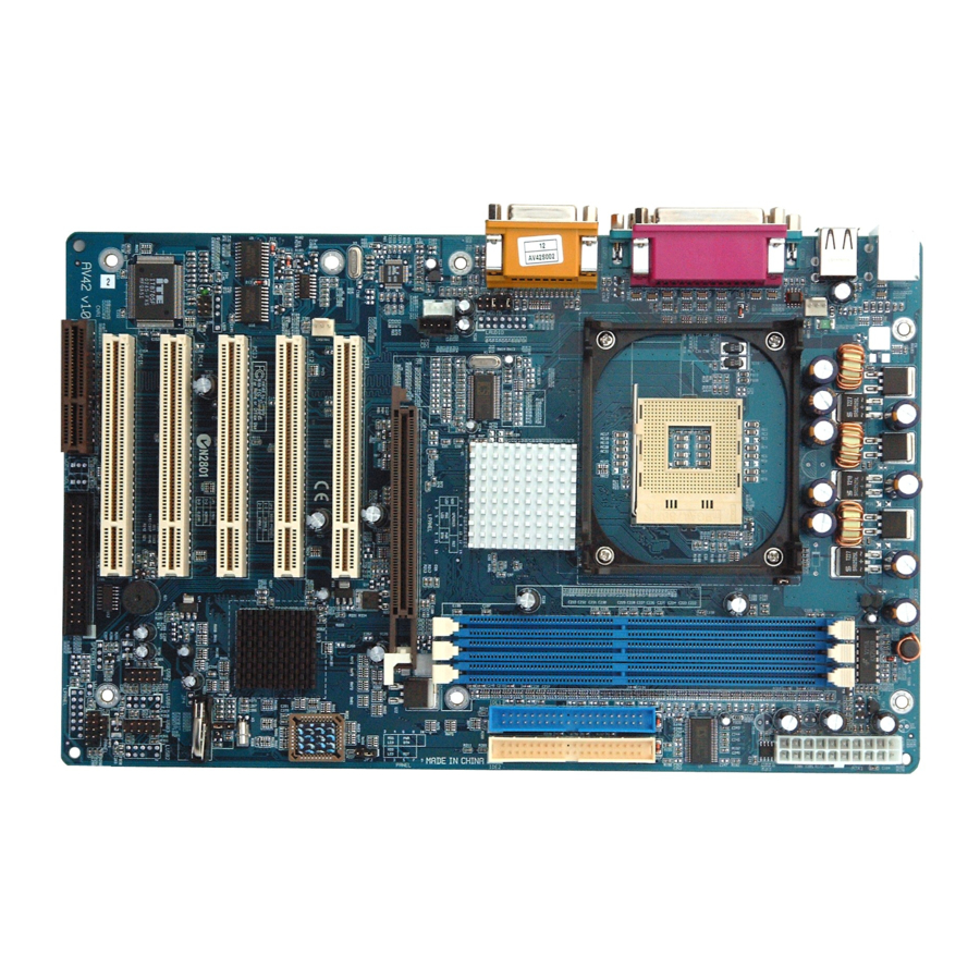
Jumpers & Connectors Guide Use the mainboard layout on page 11 to locate CPU socket, memory banks, expansion slots, jumpers and connectors on the mainboard during the instal- lation. The following list will help you to identify jumpers, slots, and connec- tors along with their assigned functions: B5~B8 C1~C4... - Page 27 Jumpers : Clear CMOS setting : BIOS written protection : CPU FSB setting Back-Panel Connectors : PS/2 mouse port : PS/2 keyboard port USB1/2 : 2 USB(Universal Serial Bus) ports COM1/2 : Serial ports 1/2 (DB9 male) LPT1 : Parallel port (DB25 female) LINE-OUT : Line-Out port LINE-IN...
-
Page 28: Clear Cmos Setting (Jp1)
1-2 if you need to reflash BIOS. Pin 1-2 (Unprotected) Pin 2-3 (Protected) CPU FSB Setting (JP5) AV42 provides jumper JP5 to configure front side bus at 400/533MHz. Short: Auto-detect (400 or 533MHz) Open: 533MHz - 26 -... -
Page 29: Back-Panel Connectors Ps/2 Mouse & Keyboard Connectors
Back-Panel Connectors PS/2 Mouse & Keyboard Connectors Two 6-pin female PS/2 Mouse & Keyboard connectors are located on the rear panel of PS/2 Mouse the mainboard. Depending on the com- puter housing you use (desktop or tower), the PS/2 Mouse connector is situated at the top of the PS/2 Keyboard connector when the mainboard is laid into a desktop, as op- posed to a tower where the PS/2 Mouse... -
Page 30: Line-Out Port Connector
Line-Out Port Connector Line-Out is a stereo output port through which the combined signal of all internal and exter- nal audio sources on the board is output. It can be connected to 1/8-inch TRS stereo Line-Out Port headphones or to amplified speakers. Line-In Port Connector Line-In is a stereo line-level input port that accepts a 1/8-inch TRS stereo plug. -
Page 31: Front-Panel Connectors Msg Led Connector (Green/Power Led)
Front-Panel Connectors MSG LED Connector (Green/Power LED) This header is dual-color LED function. Dual-color LED function is defined by either Power LED or Green LED. The Green LED indicates that the system is currently in one of the power saving modes (Doze/Standby/Suspend). When the system resumes to a normal operation mode, the Green LED will go off, and Power LED on. -
Page 32: Atx Power On/Off Switch Connector (Pwr Btn)
ATX Power On/Off Switch Connector (PWR BTN) The Power On/Off Switch is a momentary type switch used for turning on or off the system ATX power supply. Attach the connector cable from the Power Switch to the 2-pin (PWR BTN) header on the mainboard. MSG LED PWR BTN PANEL... -
Page 33: Extended Usb Headers (Usb2&3)
Extended USB Headers (USB2&3) These headers are used to connect cables to USB connectors mounted on front-panel or back-panel. The USB cable is optional at the time of purchase. Pin Assignments: Pin Assignments: VREG_FP_USBPWR0 VREG_FP_USBPWR0 USB_FP_P0- USB_FP_P1- USB_FP_P0+ USB_FP_P1+ USB_FP_OC0 USB 2&3 USB 2&3 Front-Panel Audio Header (AUDIO) -
Page 34: Internal Peripheral Connectors
Internal Peripheral Connectors Enhanced IDE and Floppy Connectors AV42 mainboard features two 40-pin dual-channel IDE device connectors (IDE1/IDE2), providing support for up to four IDE devices, such as CD-ROM and Hard Disk Drive (HDD). This mainboard also includes one 34-pin floppy disk controller (FDD1) to accommodate the Floppy Disk Drive (FDD). -
Page 35: Other Connectors Atx Power Supply Connector (Atx1)
Other Connectors ATX Power Supply Connector (ATX1) This motherboard uses 20-pin standard Pentium 4 ATX power header (ATX1). Please make sure you plug it in the right direction. ATX1 A traditional ATX system remains in the power-off stage when AC power re- sumes from power failure. -
Page 36: Cooling Fan Connectors - Cpufan1 & Casfan1
Cooling Fan Connectors - CPUFAN1 & CASFAN1 AV42 mainboard provides two onboard 12V cooling fan power connectors to support CPU (CPUFAN1), and System (CASFAN1) cooling fans. +12V SENSE CPUFAN1 Note: Both cable wiring and type of plug may vary, CASFAN1 which depend on the fan maker. -
Page 37: Single-Color Msg Led (Sj1)
Single-Color MSG LED (SJ1) This header is reserved for future use. The function of LED varies in different ACPI modes: LED becomes light in mode S0; blinking in modes S1/S3; and dark in modes S4/S5. IR Header (SIR) If you have an Infrared device, this mainboard can implement IR transfer function. -
Page 38: System Memory Configuration
3.3 System Memory Configuration AV42 mainboard has three 184-pin DIMM slots that allow you to install from 128MB to 1GB of system memory. Each 184-pin DIMM (Dual In-Line Memory Module) slot can accommodate 128MB, 256MB, 512MB, and 1GB of PC2100 compliant 2.5V single or double side 64-bit wide data path DDR SDRAM modules. -
Page 39: Software Utility
4.1 Mainboard CD Overview Note: AV42 CD-ROM is subject to change without notice. To enable your AV42 mainboard, insert it in your CD-ROM drive and the CD AutoRun screen will appear. If the AutoRun screen does not appear, double click or run D:\Autorun.exe (assuming that your CD-ROM drive is drive D:). -
Page 40: A Install Via Driver
4.2.A Install VIA Driver Click on the "Install VIA Driver" bar to install the chipset driver. Once you made your selection, the installation will run automatically. When the installation is done, reboot your computer to take the installation effect. 4.2.B Install Audio Device Driver Click on the "Install Audio Device Driver"... -
Page 41: C Install Usb 2.0 Driver
When done, reboot your computer to take the installation effect. 4.3 View the User's Manual Click on the "Manual" bar. Click on the "AV42 Manual" bar to view AV42 user's manual. Click on the "Install Acrobat Reader" if you need to install it. - 39 -... -
Page 42: Bios Setup
5 BIOS SETUP AV42 mainboard's BIOS ROM has a built-in setup program that allows users to modify the basic system configuration. The information is stored in battery- backed RAM so that it is retained even if the system power turns off. -
Page 43: The Main Menu
5.2 The Main Menu Once you enter the AwardBIOS(tm) CMOS Setup Utility, the Main Menu will appear on the screen. The Main Menu allows you to select several setup functions and two exit choices. Use the arrow keys to select among the items and press <Enter> to enter the sub-menu. Note that there is a brief description of each highlighted selection appears on the bottom of the screen. - Page 44 PC Health Status show the current system temperature, voltage, and FAN speed. Frequency/Voltage Control for setting frequency/voltage control. Load Fail-Safe Defaults to load the BIOS default values for the minimal/stable performance of your system. Load Optimized Defaults to load the factory-set BIOS default values for the optimal performance of your system.
-
Page 45: Standard Cmos Features
Standard CMOS Features The category displays under the "Standard CMOS Features." Use the arrow keys to select among the items and use the <PgUp> or <PgDn> keys to choose the value you want in each item. Date (mm : dd : yy) The item sets the date of your computer. - Page 46 Capacity Shows the disk drive capacity (approximated). Note that the size is usually slightly greater than that of a formatted disk. Ø Auto-Display your disk drive size. The following options are selectable only if the 'IDE Primary Master' item is set to 'Manual.' Cylinder Set the number of cylinders for the hard disk.
-
Page 47: Advanced Bios Features
Advanced BIOS Features The category aims at configuring the basic operation for your system. Anti-Virus Protection Allows you to choose the VIRUS Warning feature for IDE Hard Disk boot sector protection. Enabling this function prevents someone from writing data into this area, and BIOS will show a warning message on screen with an alarm beep. - Page 48 Quick Power On Self Test This item enables Power-On Self Test (POST) after you start up the computer. If it is enabled, BIOS will shorten or skip some check items during POST. Ø The choice: Disabled or Enabled. First/Second/Third Boot Device The BIOS is loaded in the operating system from the devices selected in sequence.
- Page 49 Typematic Delay (Msec) The item defines how many milliseconds must elapse before a held- down key begins generating repeat characters. Ø The choice: 250, 500, 750, or 1000. Security Option Select whether the password is required at system start-up or at entering the Setup Utility.
-
Page 50: Advanced Chipset Features
Advanced Chipset Features The category describes critical timing parameters of the mainboard. The default values are recommended unless you are quite familiar with the technical specifications of your system hardware. If not, change any value could result in fatal errors or instability in your system. DRAM Clock/Drive Control Press <Enter>... - Page 51 The following five items will become selectable if you choose the "Manual" item. SDRAM CAS Latency Ø The Choice: 3, 2.5, or 2. Bank Interleave Ø The Choice: Disabled, 2 Bank, or 4 Bank. Precharge to Active(Trp) Ø The Choice: 2T or 3T.
- Page 52 AGP Fast Write This item enables or disables the fast written function for the AGP card. Ø The Choice: Disabled or Enabled. AGP Master 1 WS Write When enabled, writing to the AGP is implemented with a single delay. Ø The Choice: Disabled or Enabled.
-
Page 53: Integrated Peripherals
Integrated Peripherals VIA OnChip IDE Device Press <Enter> to enter into the detailed options. OnChip IDE Channel0 The chipset contains a PCI IDE interface with support to two IDE chan- nels. Select enabled to activate the primary IDE interface; select dis- abled to de-activate this interface. - Page 54 Primary/Secondary Master/Slave UDMA If you install a device that supports UltraDMA that provides faster access to IDE devices, change the item to Auto. Ø The choice: Disabled or Auto. VIA OnChip PCI Device Press <Enter> to enter into the detailed options. VIA-3058 AC97 Audio This item allows you to control the onboard AC 97 audio.
- Page 55 ECP Mode Use DMA Select a DMA channel for the parallel port as using the ECP mode. Ø The choice: 1 or 3. Game Port Address This item selects the game port address. Ø The choice: Disabled, 201, or 209. Midi Port Address This item selects the MIDI port address.
-
Page 56: Power Management Setup
Power Management Setup This option has you control system power management. The system has various power-saving modes consisting of powering down the hard disk, turning off the video, suspending to RAM, and powering down the software that allows the system to be automatically resumed by certain values. - Page 57 HDD Power Down When enabled, the hard disk drive will be powered down, with all other devices remaining active. Ø The choice: Disabled or 1 Min~15 Min. Suspend Mode When enabled, all devices except the CPU will be shut off. Ø...
- Page 58 IRQ/Event Activity Detect Press <Enter> to enter into the detailed options. USB Resume from S3 When enabled, any activity from the USB device will awaken the system from S3 mode. Ø The choice: Disabled or Enabled. V G A When on, you can set the VGA to awaken the system. Ø...
- Page 59 Resume Time (hh:mm:ss) This item selects the alarm time. [hh] Ø Key in a DEC number: Min=0, Max=23. [mm/ss] Ø Key in a DEC number: Min=0, Max=59. IRQs Activity Monitoring Primary INTR Staying on will enable a specific IRQ. Ø The choice: OFF or ON.
-
Page 60: Pnp/Pci Configurations
PnP/PCI Configurations This category configures how PnP and PCI operate in your system. Correctly setting up the IRQ and DMA (both PnP and PCI use) assign- ments will make your system work stably. It is strongly recommended that only technical users make changes to the default settings. PNP OS Installed This item allows you to define if PnP OS is installed. - Page 61 PCI/VGA Palette Snoop The item is designed to solve problems caused by some non-standard VGA cards. A built-in VGA system this mainboard contains does not need this function, so please leave this item disabled. Ø The choice: Disabled or Enabled. Assign IRQ For VGA The item aims at assigning the IRQ line to the VGA on your system.
-
Page 62: Pc Health Status
PC Health Status Shutdown Temperature Enables you to set the maximum temperature the system can reach before powering down. Ø The choice: 60°C/140°F, 65°C/149°F, 70°C/158°F, Disabled. The following items provide you with information about the current operating status on your system. You cannot make any changes to one of them, including: CPU Vcore 2.50V... -
Page 63: Frequency/Voltage Control
Frequency/Voltage Control CPU Clock Ratio The item defines a multiplier for the system FSB frequency. The formula is presented as follows: Multiplier X FSB Frequency = CPU Clock Speed For example, a processor at 450MHz and FSB frequency at 100MHz ought to set the multiplier at 4.5 for: 4.5 (Multiplier) X 100MHz (FSB Frequency) = 450MHz (CPU Clock Speed). -
Page 64: Load Fail-Safe Defaults
Load Fail-Safe Defaults When you press <Enter> on this item, you will see a dialog box with a message similar to: Load Fail-Safe Defaults (Y/N)? N Press <Y> and <Enter> to install the defaults, and v.v. Load Optimized Defaults When you press <Enter> on this item, you will see a dialog box with a message similar to: Load Optimized Defaults (Y/N)? N Press <Y>... - Page 65 No Password Setting: If you want to disable the password, just press <Enter> as a password input is requested. If You Forget Password: If you forget the password, the only way to access the system is to clear the CMOS memory. Please refer to page 26 on clear CMOS setting. Save &...
Need help?
Do you have a question about the AV42 and is the answer not in the manual?
Questions and answers