
Related Manuals for Shuttle AV49V


Summary of Contents for Shuttle AV49V
- Page 1 AV49V & AV49VN Intel Pentium 4/Celeron 478-pin Processor with 400/533 MHz FSB Based DDR MAINBOARD User's Manual...
- Page 2 The information contained in this manual is provided for general use by the customers. Trademarks Shuttle is a registered trademark of Shuttle Inc. VIA is a registered trademark of VIA Corporation. Intel, Pentium, and Celeron are registered trademarks of Intel Corporation.
- Page 3 Statement of Shuttle Mainboard via the EMI Test Shuttle mainboards have been via the EMI test in terms of series of regulations: EN55022/ CISPR22/AS/NZS3548 Class B, EN55024 (1998/AS/NZS), EN4252.1 (1994), EN61000, ANSI C63.4 (1992), CFR47 Part 15 Subpart B, and CNS13438 (1997). The items tested are illus- trated as follows: (A) Voltage: AC 110V/60HZ &...
- Page 4 (D) Difference between AV49VN and AV49V: To discriminate AV49VN from AV49V lies in the extent that chips in AV49VN support LAN, and the combination for testing is based on AV49VN. (E) Supported Host Peripherals: Host Peripheral Product Name Model Name...
-
Page 5: Table Of Contents
TABLE OF CONTENTS WHAT'S IN THE MANUAL ..............5 Quick Reference ....................5 About This Manual ................... 5 1 INTRODUCTION ................6 1.1 TO DIFFERENT USERS ................6 FIRST-TIME DIY SYSTEM BUILDER............6 EXPERIENCED DIY USER ................. 6 SYSTEM INTEGRATOR................6 1.2 ITEM CHECKLIST .................. - Page 6 3.2 JUMPER SETTINGS ................. 21 JUMPERS & CONNECTORS GUIDE ............ 22 Jumpers Clear CMOS Setting (JP1) ..............24 CPU Frequency Setting (JP2) ............... 25 BIOS Flash Protection Setting (JP3) ............25 Back Panel Connectors PS/2 Mouse & PS/2 Keyboard Port Connectors ........26 Parallel Port Connector ................
- Page 7 CPU and Chassis Fan Connectors (CPUFAN1/CASFAN1) ....34 Audio CD_IN Connector (CD1) .............. 34 Internal Speaker Header (SPEAKER1) ..........34 3.3 SYSTEM MEMORY CONFIGURATION ............. 35 1. INSTALL MEMORY ................35 2. UPGRADE MEMORY ................ 35 4 SOFTWARE UTILITY ..............36 4.1 Mainboard CD Overview .................
- Page 8 LOAD OPTIMIZED DEFAULTS ..............67 SET SUPERVISOR/USER PASSWORD ........... 68 SAVE & EXIT SETUP ................69 EXIT WITHOUT SAVING ................69 - 4 -...
-
Page 9: What's In The Manual
WHAT'S IN THE MANUAL Quick Reference Hardware Installation >> Step-by-Step ..........Page 11 Jumper Settings >> A Closer Look ............Page 21 Drivers/Software Utilities >> How to Install ......... Page 36 BIOS Setup >> How to Configure ............Page 43 About This Manual For First-Time DIY System Builder ............ -
Page 10: Introduction
Experienced DIY User Congratulate on your purchase of the Shuttle AV49V/AV49VN mainboard. You will find that installing your new Shuttle AV49V/AV49VN mainboard is just easy. Bundled with an array of onboard functions, the highly-integrated AV49V/AV49VN mainboard provides you with a total solution to build the most stable and reliable system. -
Page 11: Item Checklist
1.2 Item Checklist: Check all items with your AV49V/AV49VN mainboard to make sure nothing is missing. The complete package should include: - One piece of Shuttle AV49V/AV49VN Mainboard PSKBM1 CPUFAN1 DDRDIMM2 COM1 LPT1 DDRDIMM1 DDRDIMM3 UA930084 ATX2 ATX1 IDE1 IDE2... -
Page 12: Features
2 FEATURES AV49V/AV49VN mainboard is carefully designed for the demanding PC user who wants high performance and maximum intelligent features in a compact package. 2.1 Specifications - CPU Support Intel Pentium 4/Celeron, 478-pin processors with 400/533 MHz FSB. - Chipset Features VIA APOLLO P4X400 VT8754 N.B. - Page 13 - 6 USB 2.0 Interface Onboard 2 * USB connectors on back panel and 2 sets of dual USB ports headers on mid-board. - I/O Interface Provides a variety of I/O interfaces: Ø 1* PS/2 mouse connector. Ø 1* PS/2 keyboard connector. Ø...
- Page 14 - ATX Form Factor System board conforms to ATX specification. Board dimension: 305 mm * 244 mm. - Advanced Features Ø Low EMI - Built in spread spectrum. Unused PCI/SDRAM slots are shut off by the automatic clock for reducing EMI. Ø...
-
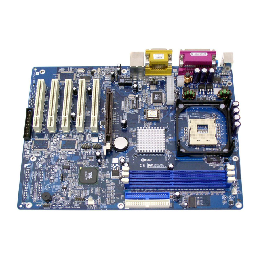
Page 15: Hardware Installation
This section outlines how to install and configure your mainboard. Referring to the follow- ing mainboard layout helps you identify various jumpers, connectors, slots, and ports. Steps described herein will lead you to a quick and correct installation of your system. 3.1 Step-by-Step Installation Accessories Of AV49V/AV49VN PSKBM1 CPUFAN1 PS/2 Mouse & PS/2... -
Page 16: Step 1 Cpu Installation
Step 1 CPU Installation: This mainboard supports Intel Pentium 4/Celeron Socket 478 series CPU. Please follow the steps as follows to finish CPU installation. Note the CPU orientation when you plug it into CPU socket. 1. Pull up the CPU socket lever to 90-degree angle. CPU socket lever up to 90-degree angle 2. -
Page 17: Step 2 Set Jumpers
Step 2. Set Jumpers The default jumper settings have been set for the common usage standard of this mainboard. Therefore, you do not need to reset the jumpers unless you require special adjustments as any of the following cases: 1. Clear CMOS 2. -
Page 18: Step 4 Install Internal Peripherals In System Case
Step 4 Install Internal Peripherals in System Case Before you install and connect the mainboard into your system case, we recommend that you first assemble all the internal peripheral devices into the computer housing, including but not limited to the hard disk drive (IDE/ HDD), floppy disk drive (FDD), CD-ROM drive, and ATX power supply unit. -
Page 19: Step 5 Mount The Mainboard On The Computer Chassis
Step 5 Mount the Mainboard on the Computer Chassis 1. You may find there are a lot of mounting holes on your computer chassis and mainboard. To match the holes on both properly, the key point is to make the back panel of the mainboard in a close fit with your system case, as shown below. -
Page 20: Step 6 Connect Front Panel Leds/Switches/Usbs
Step 6 Connect Front Panel LEDs/Switches/USBs You can find there are several different cables already existing in the system case and originating from the computer's front panel devices (HDD LED, MSG LED, Reset Switch, or USB devices etc.). These cables serve to connect the front panel LEDs, switches, and USB connectors to the mainboard's front panel, PANEL1 and USB2/USB3, as shown below. -
Page 21: Step 7 Connect Ide And Floppy Disk Drives
Step 7 Connect IDE and Floppy Disk Drives 1. IDE cable connectors IDE1 IDE2 2. Floppy cable connector FDD1 Step 8 Connect Other Internal Peripherals 1. Front panel microphone and line-out header (AUDIO1); CD_IN connector (CD1) AUDIO1 - 17 -... -
Page 22: Step 9 Connect The Power Supplies
2. Internal speaker header (SPEAKER1) SPEAKER1 Step 9 Connect the Power Supplies 1. System power connectors (ATX1/ATX2) ATX2 ATX1 Step 10 Install Add-On Cards in Expansion Slots 1. Accelerated Grapics Port (AGP) Card 2. PCI Card - 18 -... -
Page 23: Step 11 Connect External Peripherals To Back Panel
Step 11 Connect External Peripherals to Back Panel You are now ready to connect the external peripherals to your system's back panel. 1. PS/2 Mouse Port 2. PS/2 Keyboard Port 3. Parallel Port 4. Serial Port 5. MIDI/Game Port 6. Audio Line-Out Port 7. -
Page 24: Step 12 Install Drivers & Software Components
2000/ME/NT/XP operating systems only. Make sure your operating system is already installed before running the drivers installation CD-ROM programs. 1. Insert the AV49V/AV49VN bundled CD-ROM into your CD-ROM drive. The auto-run program will display the driver's main installation window on screen. -
Page 25: Jumper Settings
3.2 Jumper Settings Several hardware settings are made through the use of mini jumpers to con- nect jumper pins on the mainboard. Pin #1 could be located at any corner of each jumper, you just find the location with a white right angle which stands for pin #1. -
Page 26: Jumpers & Connectors Guide
Jumpers & Connectors Guide Use the mainboard layout on page 11 to locate CPU socket, memory banks, expansion slots, jumpers and connectors on the mainboard during the instal- lation. The following list will help you to identify jumpers, slots, and connec- tors along with their assigned functions: B4~B7 B8~B9... -
Page 27: Jumpers
Jumpers : Clear CMOS setting : CPU frequency setting : BIOS flash protection setting Back Panel Connectors : PS/2 mouse port : PS/2 keyboard port LPT1 : Parallel port (DB25 female) COM1 : Serial port (DB9 male) MIDI/GAME : MIDI/Game port (DB15 female) LINE_OUT : Line-Out port LINE_IN... -
Page 28: Clear Cmos Setting (Jp1)
Jumpers Clear CMOS Setting (JP1) JP1 is used to clear CMOS data. Clearing CMOS will result in the perma- nently erasing previous system configuration settings and the restoring origi- nal (factory-set) system settings. Pin 1-2 (Normal)(Default) Pin 2-3 (Clear CMOS) Step 1. -
Page 29: Cpu Frequency Setting (Jp2)
CPU Frequency Setting (JP2) JP2 is used to set the CPU frequency. You may choose to place the mini jumper on pins 1-2 for auto detection or on pins 2-3 if you need to run 533MHz. Pin 1-2 (Auto)(Default) Pin 2-3 (533MHz) BIOS Flash Protection Setting (JP3) JP3 is used to protect the BIOS from being unintentionally flashed. -
Page 30: Back Panel Connectors Ps/2 Mouse & Ps/2 Keyboard Port Connectors
Back Panel Connectors PS/2 Mouse & PS/2 Keyboard Port Connectors Two 6-pin female PS/2 Mouse & PS/2 Key- PS/2 Mouse board connectors are located at the rear panel of the mainboard. Depending on the computer housing you use (desktop or tower), the PS/2 Mouse connector is situ- ated at the top of the PS/2 Keyboard con- nector when the mainboard is laid into a... -
Page 31: Line-Out Port Connector
Line-Out Port Connector Line-Out is a stereo output port through which the combined signal of all internal and external audio sources on the board is output. It can be connected to 1/8-inch Line-Out Port TRS stereo headphones or to amplified speakers. -
Page 32: Front Panel Connectors Hdd Led Connector (Hddled)
Front Panel Connectors HDD LED Connector (HDDLED) Attach a connector cable from the IDE device LED to the 2-pin (HDDLED) header. The HDD LED lights up whenever an IDE device is active. PANEL1 PWRBTN MSGLED HDDLED Note : Please notice all the LED connectors are directional. If your chassis's LED does not light up during running, please change it to the oppo- site direction. -
Page 33: Green Led Connector (Msgled)
Green LED Connector (MSGLED) Connecting pins 2 and 4 to a single- or dual-color, front panel mounted LED provides power on/off, sleep, and message waiting indication. PANEL1 PWRBTN MSGLED HDDLED ATX Power On/Off Switch Connector (PWRBTN) The Power On/Off Switch is a momentary type switch used for turning on or off the ATX power supply. -
Page 34: Front Panel Microphone And Line-Out Header (Audio1)
Front Panel Microphone and Line-Out Header (AUDIO1) This header allows users to install an auxiliary Front-Oriented Microphone and Line-Out port for easier access. Either the Line-Out port connector on back panel or AUDIO1 header is available at the same time. If you would like to use this header on front panel, please remove all jumpers from this header and install your special extra microphone and line-out cable instead. -
Page 35: Extended Usb Headers (Usb2/Usb3)
Extended USB Headers (USB2 & USB3) The headers are used to connect the cables attached to USB connectors which are mounted on front panel or back panel. But the USB cable is optional at the time of purchase. USB2 USB2/USB3 USB3 Pin Assignments: 1=VREG_FP_USBPWR0 2=VREG_FP_USBPWR0... -
Page 36: Internal Peripheral Connectors Enhanced Ide And Floppy Connectors (Ide1/Ide2 & Fdd1)
Internal Peripheral Connectors Enhanced IDE and Floppy Connectors (IDE1/IDE2 & FDD1) The mainboard features two 40-pin dual-channel IDE device connectors (IDE1/IDE2), providing support for up to four IDE devices, such as CD-ROM and Hard Disk Drive (HDD). This mainboard also includes one 34-pin floppy disk controller (FDC) to accommodate the Floppy Disk Drive (FDD). -
Page 37: Other Connectors Atx Power Supply Connectors (Atx1/Atx2)
Other Connectors ATX Power Supply Connectors (ATX1/ATX2) This motherboard uses 20-pin ATX power header (ATX1), and comes with the other one header (ATX2). Please make sure you plug each in the right direction. It is essential to have these two power supply connectors plugged or your system won't boot up. -
Page 38: Cpu And Chassis Fan Connectors (Cpufan1/Casfan1)
CPU and Chassis Fan Connectors (CPUFAN1/CASFAN1) The mainboard provides two onboard 12V cooling fan power connectors to support CPU (CPUFAN1) and Chassis (CASFAN1) cooling fans. Note that both cable wiring and type of plug may vary, which depend on the fan maker. -
Page 39: System Memory Configuration
3.3 System Memory Configuration The AV49V/AV49VN mainboard has three 184-pin DIMM banks that allow you to install from 128MB up to 3GB of system memory. Each 184-pin DIMM (Dual In-line Memory Module) bank can accommodate 128MB, 256MB, 512MB, and 1GB of PC1600/PC2100/PC2700 compliant 2.5V single or double side 64-bit wide data path DDR SDRAM modules. -
Page 40: Software Utility
D:\Autorun.exe (assuming that your CD-ROM drive is drive D:). Navigation Bar Description: F Install Mainboard AV49V Software - Installing VIA 4in1, VIA Audio, and VIA USB2.0 drivers. F Install Mainboard AV49VN Software - Installing VIA 4in1, VIA LAN, VIA Audio, and VIA USB2.0 drivers. -
Page 41: Install Mainboard Software
Insert the attached CD into your CD-ROM drive and the CD AutoRun screen should appear. If the AutoRun screen does not appear, double click on Autorun icon in My Computer to bring up Shuttle Mainboard Software Setup screen. Use your pointing device (e.g. mouse) on the "Install Mainboard AV49V Software"... -
Page 42: A Install Via 4In1 Driver
4.2.A Install VIA 4in1 Driver Select using your pointing device (e.g. mouse) on the "Install VIA 4in1 Driver" bar to install the chipset driver. AV49V AV49VN Once you made your selection, a Setup window run the installation automati- cally. When the copying files is done, make sure you reboot the system to take the installation effect. -
Page 43: B Install Via Audio Driver
4.2.B Install VIA Audio Driver Select using your pointing device (e.g. mouse) on the "Install VIA Audio Driver" bar to install the audio driver. AV49V AV49VN Once you made your selection, a Setup window run the installation automati- cally. When the copying files is done, make sure you reboot the system to take the installation effect. -
Page 44: C Install Via Usb2.0 Driver
4.2.C Install VIA USB2.0 Driver Select using your pointing device (e.g. mouse) on the "Install VIA USB2.0 Driver" bar to install the USB2.0 driver. AV49V AV49VN Once you made your selection, a Setup window run the installation automati- cally. When the copying files is done, make sure you reboot the system to take the installation effect. -
Page 45: D Install Via Lan Driver (Av49Vn Only)
4.2.D Install VIA LAN Driver (AV49VN Only) Select using your pointing device (e.g. mouse) on the "Install VIA LAN Driver" bar to install the LAN driver. Once you made your selection, a Setup window run the installation automati- cally. When the copying files is done, make sure you reboot the system to take the installation effect. -
Page 46: View The User's Manual
4.3 View the User's Manual Select using your pointing device (e.g. mouse) on the "Manual" bar. Click on the "Install Acrobat Reader" bar if you need to install it, or click on "Manual" bar to view AV49V/AV49VN user's manual. - 42 -... -
Page 47: Bios Setup
5 BIOS SETUP AV49V/AV49VN BIOS ROM has a built-in Setup program that allows users to modify the basic system configuration. This information is stored in battery- backed RAM so that it retains the Setup information even if the system power is turned off. -
Page 48: The Main Menu
Note: The content of this manual is subject to any change without notice in advance. 5.2 The Main Menu Once you enter the AwardBIOS(tm) CMOS Setup Utility, the Main Menu will appear on the screen. The Main Menu allows you to select from several setup functions and two exit choices. - Page 49 Power Management Setup Use this menu to specify your settings for power management. PnP/PCI Configurations This entry appears if your system supports PnP/PCI. PC Health Status This entry shows the current system temperature, Voltage, and FAN speed. Frequency/Voltage Control Use this menu to specify your settings for frequency/voltage control. Load Fail-Safe Defaults Use this menu to load the BIOS default values for the minimal/stable performance of your system to operate.
-
Page 50: Standard Cmos Features
Standard CMOS Features The items in Standard CMOS Setup Menu are divided into 10 catego- ries. Each category includes no, one or more than one setup items. Use the arrow keys to highlight the item and then use the <PgUp> or <PgDn>... - Page 51 Halt On This item defines the operation of the system POST (Power-On Self Test) routine. You can use this item to select which situation you want the BIOS to stop the POST process and notify you. Ø The choice: All Errors, No Errors, All, But Keyboard, All, But Diskette, or All, But Disk/Key.
- Page 52 Precomp Warning: Setting a value of 65535 means no hard disk. ØMin = 0, Max = 65535 Landing Zone Set the Landing Zone size. ØMin = 0, Max = 65535 Sector Number of sector per track. ØMin = 0, Max =255 ****************************************************** - 48 -...
-
Page 53: Advanced Bios Features
Advanced BIOS Features This section allows you to configure your system for basic operation. CPU L1 & L2 Cache This item enables CPU L1 internal and L2 secondary cache to speed up the memory access. Ø The choice: Enabled or Disabled. CPU Hyper-Threading The latest Intel application defines a high-speed calculating ability to optimize your system by two CPUs supported (one virtual, one physi-... - Page 54 Boot Other Device If you enable this item, the system searches all other possible locations for and operating system if it fails to find one in the devices specified under the First, Second, and Third boot devices. Ø The choice: Enabled or Disabled. Swap Floppy Drive If you have two floppy diskette drives in your system, this item allows you to swap the assigned drive letters so that drive A becomes drive B,...
- Page 55 APIC Mode This option is used to enable or disable APIC (Advanced Programmable Interrupt Controller) functionality. Ø The choice: Enabled or Disabled. OS Select For DRAM > 64MB This item is only required if you have installed more than 64 MB of memory and you are running the OS/2 operating system.
-
Page 56: Advanced Chipset Features
Advanced Chipset Features These items define critical timing parameters of the mainboard. You should leave the items at their default values unless you are very familiar with the technical, specifications of your system hardware. If you change the val- ues incorrectly, you may introduce fatal errors or recurring instability into your system. - Page 57 Bank Interleave Not disable this item to increase SDRAM memory speed since separate memory banks are set for odd and even addresses and the next byte of memory can be accessed while the current byte is being refreshed. Ø The Choice: Disabled, 2 Bank, or 4 Bank. Precharge to Active(Trp) This item defines the numbers of cycles for RAS (row address strobe) to be allowed to precharge.
- Page 58 AGP Driving Control This item has the system automatically select its output buffer drive strength, or makes it manually selectable by an end-user. Ø The Choice: Auto or Manual. AGP Driving Value This item defines the AGP output buffer drive strength. Ø...
- Page 59 VLink 8X Support This item defines if the VLink 8X Support is enabled or not. Ø The Choice: Enabled or Disabled. Memory Hole This item is used to reserve the memory space for ISA expansion cards that require it. Ø The Choice: Disabled or 15M-16M. System BIOS Cacheable The items allow the system to be cached in memory for faster execu- tion.
-
Page 60: Integrated Peripherals
Integrated Peripherals VIA OnChip IDE Device Press <Enter> to enter the sub-menu of detailed options. OnChip IDE Channel0/Channel1 The chipset contains a PCI IDE interface with support to two IDE chan- nels. Select Enabled/Disabled to activate/deactivate the primary/second- ary IDE interface. Ø... - Page 61 VIA OnChip PCI Device Press <Enter> to enter into the detailed options. VIA-3058 AC97 Audio This item allows you to control the onboard AC97 audio. Ø The Choice: Auto or Disabled. Onboard Lan Device (AV49VN Only) This item allows you to enable or disable the onboard LAN. Ø...
- Page 62 Midi Port IRQ This item defines an interrupt request for the MIDI port. Ø The choice: 5 or 10. Init Display First This item is used to determine initial device when system power on. Ø The choice: PCI Slot or AGP. OnChip USB Controller Do not disable this item if your system has a USB installed on the sys- tem board and you want to use it.
-
Page 63: Power Management Setup
Power Management Setup The Power Management Setup allows you to configure your system to most effectively saving energy. ACPI Function This item defines the ACPI (Advanced Configuration and Power Man- agement) feature that makes hardware status information available to the operating system, enables a PC to turn its peripherals on or off for improving the power management, and allows a PC turned on or off by external devices, so that a mouse or keyboard can wake up it. - Page 64 Suspend Mode When this item is not disabled and after the setup time of system inactiv- ity, all devices except the CPU will be shut off. Ø The choice: Disabled, 1 Min, 2 Min, 4 Min, 6 Min, 8 Min, 10 Min, 20 Min, 30 Min, 40 Min, or 1 Hour.
- Page 65 When select ON, you can set the VGA to awaken the system. Ø The choice: OFF or ON. LPT & COM When each or both stay on, any activity from one of the peripheral devices or IRQs will wake up the system. Ø...
- Page 66 A cluster of IRQs is listed as follows. As one certain IRQ is enabled, any activity at it will awaken the system from a power-saving mode. IRQ3 (COM 2) IRQ4 (COM 1) IRQ5 (LPT 2) IRQ6 (Floppy Disk) IRQ7 (LPT 1) IRQ8 (RTC Alarm) IRQ9 (IRQ2 Redir) IRQ10 (Reserved)
-
Page 67: Pnp/Pci Configurations
PnP/PCI Configurations This category configures how PnP and PCI operate in your system. Correctly setting up the IRQ and DMA (both PnP and PCI use) assign- ments will make your system work stably. It is strongly recommended that only technical users make changes to the default settings. PNP OS Installed This item allows you to determine PnP OS is installed or not. - Page 68 Assign IRQ For VGA The item aims at assigning the IRQ line to the VGA on your system. When Enabled, activity from the VGA will awaken the system. Ø The choice: Disabled or Enabled. Assign IRQ For USB The item aims at assigning the IRQ line to the USB on your system. When Enabled, activity from the USB will awaken the system.
-
Page 69: Pc Health Status
PC Health Status Shutdown Temperature Enables you to set the maximum temperature that system can reach before powering down. Ø The choice: 60°C/140°F, 65°C/149°F, 70°C/158°F, or Disabled. The following items provide you with information about the system's cur- rent operating status. You cannot make changes to one of them, including: CPU Vcore 2.50 V 3.30 V... -
Page 70: Frequency/Voltage Control
Frequency/Voltage Control CPU Clock Ratio This item allows you to adjust CPU Ratio. The item becomes unavail- able if your CPU clock ratio is locked. CPU Voltage Regulator This item defines the CPU core voltage. Ø The choice: Default, +2%, +4%, or +6%. DDR Voltage Regulator This item defines the DDR voltage. -
Page 71: Load Fail-Safe Defaults
Load Fail-Safe Defaults When you press <Enter> on this item, you will get a confirmation dialog box with a message similar to: Load Fail-Safe Defaults (Y/N) ? N Pressing 'Y' loads the BIOS default values for the most stable, minimal performance system operations. - Page 72 Set Supervisor/User Password Steps to set supervisor/user password are described as follows: New Password Setting: 1. While pressing <Enter> to set a password, a dialog box appears to ask you enter a password. 2. Key in a new password. The password can not exceed eight charac- ters.
- Page 73 Save & Exit Setup Pressing <Enter> on this item asks for confirmation: SAVE to CMOS and EXIT (Y/N) ? Y Pressing "Y" stores the selections made in the menus of CMOS - a special section of memory that stays on after you turn your system off. The next time you boot your computer, the BIOS configures your system according to the Setup selections stored in CMOS.
Need help?
Do you have a question about the AV49V and is the answer not in the manual?
Questions and answers