Table of Contents
Advertisement
Quick Links
Advertisement
Table of Contents

Subscribe to Our Youtube Channel
Related Manuals for Shuttle AI61


Summary of Contents for Shuttle AI61
- Page 1 AI61 AMD K7 processor Based AGP MAIN BOARD User's Manual - 69 -...
- Page 2 AI61 AMD K7 processor based AGPset Mainboard Manual Version 1.1 Disclaimer The manufacturer makes no representations or warranties regarding the contents of this manual. Information in this manual has been carefully checked for reliability; however, no guarantee is given as to the correctness of the contents. In the interest of continued product...
-
Page 3: Table Of Contents
2 FEATURES..................7 2.1 SPECIFICATIONS ..................7 3 HARDWARE INSTALLATION............10 3.1 STEP BY STEP INSTALLATION..............1 0 Accessories Of AI61 ................10 STEP 1 Install the CPU ................11 STEP 2 Set Jumpers ................12 STEP 3 Install SDRAM System Memory ..........12 STEP 4 Install Internal Peripherals in System Case ....... - Page 4 STEP 11 Connect External Peripherals to Back Panel......19 STEP 12 First Time System Boot Up ............20 STEP 13 Install Drivers & Software Components ........21 3.2 JUMPER SETTINGS ................... 2 2 Jumpers & Connectors Guide ..............23 Clear CMOS (J4) ..................25 Vcore Voltage Setting (J13)..............
- Page 5 4 SOFTWARE UTILITY ..............34 4.1 AI61 MAINBOARD CD OVERVIEW ............34 4.2 INSTALL MAINBOARD DRIVER............... 3 5 4.3 INSTALL AGP AND IRQ MINIPORT DRIVER ...........36 4.4 TO VIEW THE USER'S MANUAL..............37 5 BIOS SETUP ................38 5.1 ENTERING BIOS..................3 8 5.2 THE MAIN MENU..................
-
Page 6: What's In The Manual
WHAT’S IN THE MANUAL Quick Reference Hardware Installation >> Step-by-Step ..........Page 10 Jumper Settings >> A Closer Look............Page 22 Software Utility >> How to Install............Page 34 BIOS Setup >> How to Configure............Page 38 About This Manual For First-Time DIY System Builder............Page 5 For Experienced DIY User...............Page 5 For System Integrator................ -
Page 7: Introduction
Experienced DIY User Congratulations on your purchase of the AI61 mainboard. You will find that installing your new AI61 mainboard is just that easy. Bundled with an array of onboard functions, the highly-integrated AI61 mainboard provides you with a total solution to build the most stable and reliable system. Refer to section 3.2 Jumper Settings and Chapter 4 Software Utility to find out how to get the best out of your new mainboard. -
Page 8: Item Checklist
1.2 Item Checklist Check all items you received with your AI61 mainboard to make sure nothing is missing. The complete package should include: One AI61 Mainboard (with onboard Slot A, built-in AMD-751 chipset, ATX form factor, including 2xUSB, 2xSerial, and 1xParallel ports, plus 1xPS/2 Keyboard, and 1xPS/2 Mouse connectors.) -
Page 9: Features
2 FEATURES The AI61 mainboard is carefully designed for the demanding PC user who wants high performance and maximum intelligent features in a compact package. 2.1 Specifications CPU Support AMD K7 processor 500 ~ 750+MHz Chipset Features AMD-751and AMD-756 AGPset with I/O subsystems. - Page 10 2 × DB9 Serial connectors 16550 UART compatible 1 × Infrared communications port ASKIR and HPSIR compatible. (Serial port COM2 can also be redirected to an external IrDA Adapter for wireless connection.) 1 × DB25 Parallel port supporting Standard Parallel Port (SPP), Enhanced Parallel Port (EPP), and Extended Capabilities Port (ECP) data transmission schemes.
- Page 11 Advanced Features Dual Function Power Button - The system can be in one of two states, one is Suspend mode and the other is Soft-Off mode. Pushing the power button for less than 4 seconds places the system into Suspend mode. When the power button is pressed for longer than 4 seconds, the system enters the Soft-Off mode.
-
Page 12: Hardware Installation
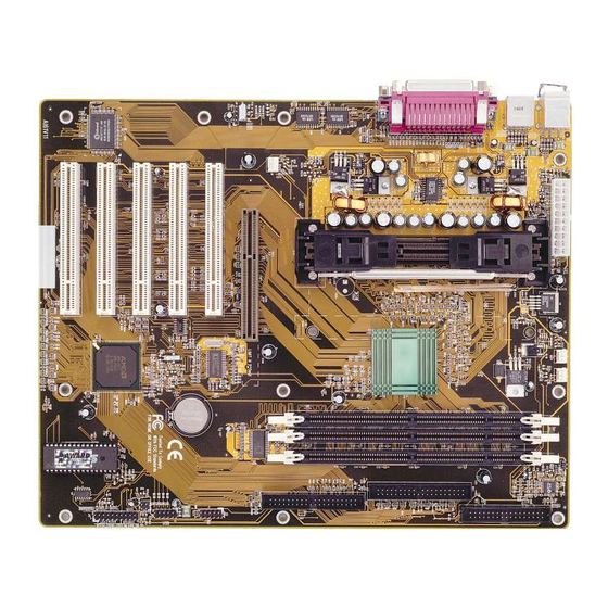
3 HARDWARE INSTALLATION This section outlines how to install and configure your AI61 mainboard. Refer to the following mainboard layout to help you identify various jumpers, connectors, slots, and ports. Then follow these steps designed to guide you through a quick and correct instal- lation of your system. -
Page 13: Step 1 Install The Cpu
Step 1 Install the CPU 1. Mark your CPU Frequency Checking the working frequency of your cpu that should be clearly marked on the CPU cover or write your own combination in the space provided. AMD K7 Processor Installation <Locate the Retention Mechanism> To install a CPU, first turn off your system and remove its cover. -
Page 14: Step 2 Set Jumpers
Step 2. Set Jumpers This mainboard is jumperless! The default jumper settings have been set for the common usage standard of this mainboard. Therefore, you do not need to reset the jumpers unless you require special adjustments as clear CMOS. For first-time DIY system builders, we recommend that you do not change the default jumper settings if you are not totally familiar with mainboard configuration procedures. -
Page 15: Step 4 Install Internal Peripherals In System Case
Step 4 Install Internal Peripherals in System Case Before you install and connect the mainboard into your system case, we recommend that you first assemble all the internal peripheral devices into the computer housing, including but not limited to the hard disk drive (IDE/ HDD), floppy disk drive (FDD), CD-ROM drive, and ATX power supply unit. -
Page 16: Step 5 Mount The Mainboard On The Computer Chassis
Step 5 Mount the Mainboard on the Computer Chassis 1. You may find that there are a lot of different mounting hole positions both on your computer chassis and on the mainboard. To choose a correct mounting hole, the key point is to keep the back-panel of the mainboard in a close fit with your system case, as shown below. -
Page 17: Step 6 Connect Front Panel Switches/Leds/Speaker
Step 6 Connect Front Panel Switches/LEDs/Speaker You can find there are several different cables already existing in the system case and originating from the computer’s front-panel devices (HDD LED, Power LED, Reset Switch, PC Speaker, etc.) These cables serve to connect the front-panel switches and LEDs and USB connectors to the mainboard’s front-panel connectors group, (J12 and J2) as shown below. - Page 18 3. HDD-LED 4. Power-LED / G-LED 5. PC Speaker 6. Keylock 7. Hardware Reset Switch 8. Front panel USB conneting header - 16 -...
-
Page 19: Step 7 Connect Ide & Floppy Disk Drives
Step 7 Connect IDE & Floppy Disk Drives 1. IDE cable connector 2. FDD cable connector Step 8 Connect Other Internal Peripherals 1. SIR/CIR connector - 17 -... -
Page 20: Step 9 Connect The Power Supply
Step 9 Connect the Power Supply 1. System power connector Step 10 Install Add-on Cards in Expansion Slots 1. Accelerated Graphics Port (AGP) Card 2. PCI Card - 18 -... -
Page 21: Step 11 Connect External Peripherals To Back Panel
Step 11 Connect External Peripherals to Back Panel You are now ready to put the computer case back together and get on to the external peripherals connections to your system’s back-panel. 1. PS/2 Mouse and Keyboard PS/2 Mouse PS/2 keyboard 2. -
Page 22: Step 12 First Time System Boot Up
Step 12 First Time System Boot Up To assure the completeness and correctness of your system installation, you may check the above installation steps once again before you boot up your system for the first time. 1. Insert a bootable system floppy disk (DOS 6.2x, Windows 95/98/NT, or others) which contains FDISK and FORMAT utilities into the FDD. -
Page 23: Step 13 Install Drivers & Software Components
Make sure your Windows 9x operating system is already installed before running the drivers installation CD-ROM programs. 1. Insert the AI61 bundled CD-ROM into your CD-ROM drive. The auto-run program will display the drivers main installation window on screen. -
Page 24: Jumper Settings
3.2 Jumper Settings Several hardware settings are made through the use of jumper caps to connect jumper pins on the mainboard. Pin #1 is located on the bottom or on the left when holding the mainboard with the keyboard connector or other back-panel connectors opposite from you, as shown below. -
Page 25: Jumpers & Connectors Guide
Jumpers & Connectors Guide Use the mainboard layout on page 10 to locate CPU socket, memory banks, expansion slots, jumpers and connectors on the mainboard during the installation. The following list will help you identify jumpers, slots, and connectors along with their assigned functions: CPU/Memory/Expansion Slots Slot A : CPU Slot for AMD K7 processors... - Page 26 Front Panel Connectors (J12) PW_ON : ATX Power On/Off Momentary Type Switch : Hardware System Management Interface Momentary Type switch. H_LED : IDE Drive Active LED P_LED/G_LED : System Power LED/Green LED SPEAKER : Housing Internal Speaker KLOCK : KEYLOCK : Hardware Reset Switch USB3/4 : Front Panel USB Connector Header (J2)
-
Page 27: Clear Cmos (J4)
Step 3. Remove jumper from to J4 Step 4. Turn on the system power (PC-> On) Vcore Voltage Setting (J13) J13 is used to adjust voltages. Futher more, AI61 Mainboard provide intelli- gent CPU Voltages detecting and auto-adjusting function. Vcore Voltage Setting - J13 AUTO 1.30V... -
Page 28: Ps/2 Keyboard & Ps/2 Mouse Connectors
PS/2 Keyboard & PS/2 Mouse Connectors Two 6-pin female PS/2 keyboard & Mouse connectors are located at the rear panel PS/2 Mouse of the mainboard. Depending on the com- puter housing you use (desktop or minitower), the PS/2 Mouse connector is situated at the top of the PS/2 Keyboard connector when the mainboard is laid into PS/2 keyboard... -
Page 29: Atx Power On/Off Switch Connector (Pw_On)
ATX Power On/Off Switch Connector (PW_ON) The Power On/Off Switch is a momen- tary type switch used for turning on or off the system’s ATX power supply. Attach the connector cable from the Power Switch to the 2-pin PWON header on the mainboard. -
Page 30: Hdd Led Connector (H_Led)
HDD LED Connector (H_LED) Attach the connector cable from the IDE device LED to the 2-pin HDD LED header. The HDD LED lights up whenever an IDE device is active. PWR LED/Green LED Connector (P_LED) Attach the 2-pin Power-LED connector cable from the housing front panel to the PWR header on the mainboard. -
Page 31: Hardware Reset Connector (Rst)
Hardware Reset Connector (RST) Attach the 2-pin hardware reset switch cable to the RST header. Pressing the reset switch causes the system to restart. Front Panel USB Connector Header (J2) This deader used to connect the cable at- tached to USB connectors which mounted on front panel. -
Page 32: Enhanced Ide Ports And Floppy Connectors
Enhanced IDE Ports and Floppy Connector The AI61 mainboard features two 40-pin dual-channel IDE device connec- tors (IDE1/IDE2) providing support for up to four IDE devices, such as CD- ROM and Hard Disk Drives (H.D.D.). This mainboard also includes one 34-pin floppy disk controller (FDC) to accommodate the Floppy Disk Drive (F.D.D.). -
Page 33: Atx Power Supply Connector
ATX Power Supply Connector Locate the 20-pin male header ATX power connector on your mainboard. Plug the power cable from the ATX power supply unit directly into ATX power supply connector. Note 1: The ATX power connector is directional and will not go in unless the guides match perfectly making sure that pin#1 is properly positioned. -
Page 34: Sir/Cir Connector (J1)
SIR/CIR Connector (J1) If you have an Infrared device, this mainboard can implement SIR (Standard IR) and CIR (Cirsumer IR) transfer function. To enable the IR transfer func- tion, follow these steps: SIR Pin Assignments: 1=VCC 3=RRXH 5=IRRX 7=GND 9=IRTX CIR Pin Assignments: 2=NC 4=SR-CIRRX 6=VCC 8=NC 10=NC... -
Page 35: System Memory Configuration
3.3 System Memory Configuration The AI61 mainboard has three 168-pin DIMM sockets that allow you to install from 16MB up to 768MB of system memory with SDRAM (Synchro- nous DRAM). Each DIMM (Dual In-line Memory Module) socket can accommodate 16MB, 32MB, 64MB, 128MB, and 256MB 3.3V single or double side SDRAM modules. -
Page 36: Software Utility
4 SOFTWARE UTILITY 4.1 AI61 Mainboard CD Overview Note: The AI61 mainboard attachment CD contents are subject to change without notice. To start your mainboard CD disc, just insert it into your CD-ROM drive and the CD AutoRun screen should appear. If the AutoRun screen does not appear, double click or run D:\Autorun.exe (assuming that your CD-ROM... -
Page 37: Install Mainboard Driver
4.2 Install Mainboard Driver Insert the attachment CD into your CD-ROM drive and the CD AutoRun screen should appear. If the AutoRun screen does not appear, double click on Autorun icon in My Computer to bring up Mainboard Software Setup screen. -
Page 38: Install Agp And Irq Miniport Driver
4.3 Install AGP and IRQ Miniport Driver Insert the attachment CD into your CD-ROM drive and the CD AutoRun screen should appear. If the AutoRun screen does not appear, double click on Autorun icon in My Computer to bring up Mainboard Software Setup screen. -
Page 39: To View The User's Manual
Select using your pointing device (e.g. mouse) on the “Manual” bar. Then Online Information windows will appear on your screen. Click on the “Install Acrobe Reader 3.0” bar if you need to install acrobe reader. Then click on "AI61 Manual" bar to view AI61 user's manual. - 37 -... -
Page 40: Bios Setup
5 BIOS SETUP AI61 BIOS ROM has a built-in Setup program that allows users to modify the basic system configuration. This information is stored in battery-backed RAM so that it retains the Setup information even if the system power is turned off. -
Page 41: The Main Menu
5.2 The Main Menu Once you enter the AwardBIOS(tm) CMOS Setup Utility, the Main Menu will appear on the screen. The Main Menu allows you to select from several setup functions and two exit choices. Use the arrow keys to select among the items and press <Enter> to accept and enter the sub-menu. - Page 42 Integrated Peripherals Use this menu to specify your settings for integrated peripherals. Power Management Setup Use this menu to specify your settings for power management. PnP / PCI Configuration This entry appears if your system supports PnP / PCI. PC Health Status This entry shows the current system temperature, Voltage and FAN speed.
-
Page 43: Standard Cmos Setup
Standard CMOS Setup The items in Standard CMOS Setup Menu are divided into 10 catego- ries. Each category includes no, one or more than one setup items. Use the arrow keys to highlight the item and then use the <PgUp> or <PgDn>... - Page 44 IDE Secondary Master Options are in its sub menu. Press <Enter> to enter the sub menu of detailed options. IDE Secondary Slave Options are in its sub menu. Press <Enter> to enter the sub menu of detailed options. Drive A/Drive B Select the type of floppy disk drive installed in your system.
- Page 45 ****************************************************** IDE Adapters The IDE adapters control the hard disk drive. Use a separate sub menu to configure each hard disk drive. IDE HDD Auto-detection Press Enter to auto-detect the HDD on this channel. If detection is successful, it fills the remaining fields on this menu. Press Enter IDE Primary Master Selecting 'manual' lets you set the remaining fields on this screen.
- Page 46 Precomp Warning: Setting a value of 65535 means no hard disk. Min = 0, Max = 65535 Landing zone Set the Landing zone size. Min = 0, Max = 65535 Sector Number of sectors per track. Min = 0, Max = 255 ****************************************************** - 44 -...
-
Page 47: Bios Features Setup
Advanced BIOS Features This section allows you to configure your system for basic operation. You have the opportunity to select the system's default speed, boot-up sequence, keyboard operation, shadowing and security. Virus Warning Allows you to choose the VIRUS Warning feature for IDE Hard Disk boot sector protection. - Page 48 External Cache This item enables CPU secondary cache to speed up memory access. The choice: Enabled, Disabled. Quick Power On Self Test This item speeds up Power On Self Test (POST) after you power on the computer. If it is set to Enabled, BIOS will shorten or skip some check items during POST.
- Page 49 Gate A20 Option This entry allows you to select how the gate A20 is handled. The gate A20 is a device used to address memory above 1 MByte. Initially, the gate A20 was handled via a pin on the keyboard. Today, while key- boards still provide this support, it is more common, and much faster, set to Fast for the system chipset to provide support for gate A20.
- Page 50 Note: To disable security, select PASSWORD SETTING at Main Menu and then you will be asked to enter password. Do not type anything and just press <Enter>, it will disable security. Once the security is disabled, the system will boot and you can enter Setup freely.
-
Page 51: Chipset Features Setup
Advanced Chipset Features This section allows you to configure the system based on the specific features of the installed chipset. This chipset manages bus speeds and access to system memory resources, such as DRAM and the external cache. It also coordinates communications between the conventional ISA bus and the PCI bus. - Page 52 Memory Hole At 15M-16M You can reserve this area of system memory for ISA adapter ROM. When this area is reserved, it cannot be cached. The user information of peripherals that need to use this area of system memory usually discusses their memory requirements.
- Page 53 SDRAM PH Limit This item set the number of consecutive page-hit requests to allow before choosing a non-page-hit request. The choice: 1 Cycle, 4 Cycle, 32 Cycle, 64 Cycle, SDRAM Idle Limit This item set the number of idle cycles to wait before precharging an idle bank.
-
Page 54: Integrated Peripherals
Integrated Peripherals IDE Read/Write Prefetch Enabled/Disabled IDE Read/Write Prefetch buffer. The choice: Enabled, Disabled. IDE Primary/Secondary Master/Slave PIO The four IDE PIO (Programmed Input/Output) fields let you set a PIO mode (0-4) for each of the four IDE devices that the onboard IDE interface supports. - Page 55 OnChip Primary/Secondary PCI IDE The integrated peripheral controller contains an IDE interface with support for two IDE channels. Select Enabled to activate each channel separately. The choice: Enabled, Disabled. USB Host Controller Select Enabled if your system contains a Universal Serial Bus (USB) controller and you have USB peripherals.
- Page 56 Onboard Serial Port 1 This item is used to define onboard serial port 1. The choice: 3F8/IRQ4, 2F8/IRQ3, 3E8/IRQ4, 2E8/IRQ3, Auto, Disabled. Onboard Serial Port 2 This item is used to define onboard serial port 2. The choice: 3F8/IRQ4, 2F8/IRQ3, 3E8/IRQ4, 2E8/IRQ3, Auto, Disabled.
- Page 57 Parallel Port Mode This item specifies onboard parallel port mode. The options are SPP (Standard Parallel Port), EPP(Enhanced Parallel Port), ECP (Extended Capabilities Port), and EPP+ECP. The choice: SPP, EPP, ECP, EPP+ECP. ECP Mode Use DMA This item specifies DMA (Direct Memory Access) channel when ECP device is in use.
-
Page 58: Power Management Setup
Power Management Setup The Power Management Setup allows you to configure you system to most effectively save energy while operating in a manner consistent with your own style of computer use. ACPI Function This item allows you to enable/disable the Advanced Configuration and Power Management (ACPI). - Page 59 User Defined Allows you to set each mode individually. When not disabled, each of the ranges are from 1 min. to 1 hr. except for HDD Power Down which ranges from 1 min. to 15 min. and disable. The choice: Min Saving, Max Saving, User Define. Video Off Method This determines the manner in which the monitor is blanked.
- Page 60 Soft-Off by PBTN Pressing the power button for more than 4 seconds forces the system to enter the Soft-Off state when the system has "hung." The choice: Delay 4 Sec, Instant-Off. Wake-Up by PCI card This item Enabled/Disabled PCI card wakeup for PCI Spec 2.2. The choice: Enabled, Disabled.
- Page 61 *** Reload Global Timer Events *** If any of these items is set to Disabled, that system activity event will not be monitored to reload global timer. If these items is set to Enabled, that system activity event will be monitored to reload global timer.
-
Page 62: Pnp/Pci Configuration
PnP/PCI Configuration This section describes configuring the PCI bus system. PCI, or Per- sonal Computer Interconnect, is a system which allows I/O devices to operate at speeds nearing the speed the CPU itself uses when commu- nicating with its own special components. This section covers some very technical items and it is strongly recommended that only experi- enced users should make any changes to the default settings. - Page 63 Plug and Play operating system such as Windows 95. If you set this field to "manual" choose specific resources by going into each of the sub menu that follows this field (a sub menu is preceded by a ">"). The choice: Auto(ESCD), Manual. IRQ Resources When resources are controlled manually, assign each system interrupt a type, depending on the type of device using the interrupt.
-
Page 64: Pc Health Status Setup
PC Health Status CPU Warning Temperature Since the mainboard support CPU temperature monitoring and over- hear alert. This item allows the user to set the threshold of CPU warning temperature. When CPU temperature over the threshold, system will slow down clock to prevent CPU damage. The choice: Disabled, 50°C/122°F, 53°C/127°F, 56°C/133°F, 60°C/140°F, 63°C/145°F, 66°C/151°F, 70°C/158°F. - Page 65 VCORE, +3.3V, +5V ~ -5V, +12V ~ -12V The mainboard support CPU and mainboard voltages monitoring. The onboard hardware monitor is able to detect the voltages output of the voltage regulators and power supply. VBAT(V) Battery voltage. Shutdown Temperature Select the combination of lower and upper limits for the system shut- down temperature, if your computer contains an environmental moni- toring system.
-
Page 66: Frequency/Voltage Control
Frequency/Voltage Control Auto Detect DIMM/PCI Clk This item allows you to enable/disable auto detect DIMM/PCI Clock. The choice: Enabled, Disabled. Spread Spectrum Modulated This item allows you to enable/disable the spread spectrum modulate. The choice: Enabled, Disabled. CPU Host/PCI Clock The choice: Default, 50/25MHz, 66/33MHz, 100/33MHz, 133/33MHz. -
Page 67: Load Fail-Safe Defaults
Load Fail-Safe Defaults When you press <Enter> on this item you get a confirmation dialog box with a message similar to: Load Fail-Safe Defaults (Y/N) ? N Pressing 'Y' loads the BIOS default values for the most stable, minimal-performance system operations. Load Optimized Defaults When you press <Enter>... -
Page 68: Supervisor Password Setting
Supervisor/User Password Setting You can set either supervisor or user password, or both of then. The differences between are: Supervisor Password and User Password The options on the Password screen menu make it possible to restrict access to the Setup program by enabling you to set passwords for two different access modes: Supervisor mode and User mode. -
Page 69: Save & Exit Setup
Password Disable If you select System at Security Option of BIOS Features Setup Menu, you will be prompted for the password every time the system is rebooted or any time you try to enter Setup. If you select Setup at Security Option of BIOS Features Setup Menu, you will be prompted only when you try to enter Setup.
Need help?
Do you have a question about the AI61 and is the answer not in the manual?
Questions and answers