
Related Manuals for Shuttle AV49


Summary of Contents for Shuttle AV49
- Page 1 AV49/AV49N Socket 478 Pentium 4/Celeron, 478-pin Processor with 400/533 MHz FSB Based MAIN BOARD User's Manual...
- Page 2 The information contained in this manual is provided for general use by the customers. Trademarks Shuttle is a registered trademark of Shuttle Inc. Intel, Pentium is a registered trademarks of Intel Corporation. VIA is a registered trademark of VIA Corporation.
-
Page 3: Table Of Contents
2.1 SPECIFICATIONS ..................8 3 HARDWARE INSTALLATION ............11 3.1 STEP BY STEP INSTALLATION..............11 Accessories of AV49/AV49N ..............11 STEP 1 Install the CPU ................12 STEP 2 Set Jumpers ................14 STEP 3 Install DDR SDRAM System Memory ........14 STEP 4 Install Peripherals in System Case.......... - Page 4 STEP 13 Install Drivers & Software Components ........25 3.2 JUMPER SETTINGS .................. 26 JUMPERS & CONNECTORS GUIDE ............ 27 Jumpers Clear CMOS Setting (JP1) ..............30 FSB Speed Configuration Setting (JP2) ..........30 USB Power on Setting (JP3/JP4) ............31 BIOS Flash Protect Setting (JP5)............
- Page 5 Internal Peripherals Connectors Enhanced IDE and Floppy Connector ............38 Other Connectors ATX Power Supply Connector (ATX1/ATX2) ..........39 Cooling Fan Connectors for CPU, Chipset, Chassis (FAN1/2/3) ....40 Wake-on Lan Connector (WOL) ..............40 Front-Panel Audio Header(J5) ............... 41 Audio CD-IN Connectors (J7/J8) (White/Black) ...........
- Page 6 ADVANCED BIOS FEATURES ..............59 ADVANCED CHIPSET FEATURES ............62 INTEGRATED PERIPHERALS ..............67 POWER MANAGEMENT SETUP .............. 71 PNP/PCI CONFIGURATION ............... 76 PC HEALTH STATUS ................. 78 FREQUENCY/VOLTAGE CONTROL ............79 LOAD FAIL-SAFE DEFAULTS ..............80 LOAD OPTIMIZED DEFAULTS ..............80 SET SUPERVISOR PASSWORD ..............
-
Page 7: What's In The Manual
WHAT'S IN THE MANUAL Quick Reference Hardware Installation >> Step-by-Step ............Page 11 Jumper Settings >> A Closer Look ............Page 26 Drivers/Software Utilities >> How to Install ..........Page 45 BIOS Setup >> How to Configure ............... Page 52 About This Manual For First-Time DIY System Builder ..............Page 6 For Experienced DIY User ................Page 6 For System Integrator ..................Page 6... -
Page 8: Introduction
Shuttle AV49/N mainboard. Experienced DIY User Congratulate on your purchase of the Shuttle AV49/N mainboard. You will find that installing your new Shuttle AV49/AV49N mainboard is just easy. Bundled with an array of onboard functions, the highly-integrated AV49/AV49N mainboard provides you with a total solution to build the most stable and reli- able system. -
Page 9: Item Checklist
1.2 Item Checklist Check all items with you AV49/AV49N mainboard to make sure nothing is missing. The complete package should include: One piece of Shuttle AV49/AV49N Mainboard One piece of ATA 133/100 133/100 133/100 133/100 Ribbon Cable 133/100 ... -
Page 10: Features
2 FEATURES AV49/AV49N mainboard is carefully designed for the demanding PC user who wants high performance and maximum intelligent features in a compact package. 2.1 Specifications - CPU Support Intel Pentium 4/Celeron , 478-pin processors with 400/533 MHz FSB. - Chipset Features VIA P4X400 N.B. - Page 11 Ø 1× Infrared communication port. (Serial port COM2 can also be redirected to an external IrDA Adapter for wireless connection.) Ø 1× DB25 Parallel port supports Standard Parallel Port and Bi-directional (SPP), Enhanced Parallel Port (EPP), and Extended Capabilities Port (ECP) data transmission schemes.
- Page 12 ATX Form Factor System board conforms to ATX specification. Board dimension: 350mm*190mm. Advanced Features Ø Low EMI - Low EMI - Low EMI - Low EMI - Built in spread spectrum and automatic clock shut-off of Low EMI - unused PCI/SDRAMS slots to reduce EMI.
-
Page 13: Hardware Installation
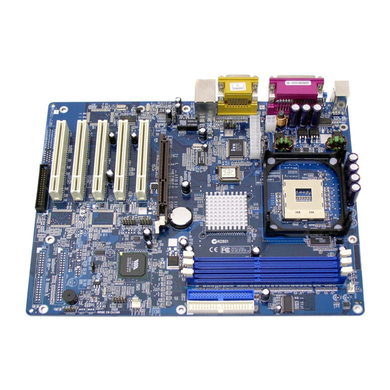
Then follow these steps designed to guide you through a quick and correct installation of your system. 3.1 Step-by-Step Installation Accessories Of AV49/AV49N VIA P4X400 Chipset SOCKET 478 ATX 12V Power... -
Page 14: Step 1 Install The Cpu
Step 1. CPU Installation: This mainboard supports Intel Pentium 4/Celeron Socket 478 series CPU. Please follow the step as below to finish CPU installation. Be careful of CPU orientation when you plug it into CPU socket. 1. Pull up the CPU socket lever and up to 90-degree angle. CPU socket lever up to 90 degree 2. - Page 15 3. Press down the CPU socket lever and finish CPU installation. Note: Note: If you do not match the CPU socket Pin 1 and CPU cut edge Note: Note: Note: well, it may damage the CPU. 4. The Intel Pentium 4/Celeron processor requires a set of heatsink/fan to ensure proper cooling of the processor.
-
Page 16: Step 2 Set Jumpers
Step 2. Set Jumpers This mainboard is jumperless! The default jumper settings have been set for the common usage standard of this mainboard. Therefore, you do not need to reset the jumpers unless you require special adjustments as any of the following cases: 1. -
Page 17: Step 4 Install Peripherals In System Case
Step 4. Install Internal Peripherals in System Case Before you install and connect the mainboard into your system case, we recommend that you first assemble all the internal peripheral devices into the computer housing, including but not limited to the hard disk drive (IDE/ HDD), floppy disk drive (FDD), CD-ROM drive, and ATX power supply unit. -
Page 18: Step 5 Mount The Mainboard On The Computer Chassis
Step 5. Mount the Mainboard on the Computer Chassis 1. You may find that there are a lot of different mounting hole positions both on your computer chassis and on the mainboard. To choose correct mounting holes, the key point is to keep the back-panel of the mainboard in a close fit with your system case, as shown below. -
Page 19: Step 6 Connect Front Panel Switches/Leds/Speaker/Usb
Step 6. Connect Front Panel Switches/LEDs/Speaker/USB You can find there are several different cables already existing in the system case and originating from the computer's front-panel devices (HDD LED, Power LED, Reset Switch, PC Speaker, or USB devices etc.) These cables serve to connect the front-panel switches, LEDs, and USB connectors to the mainboard's front-panel connectors group (J1 and USB2/3), as shown below. - Page 20 4. ATX Soft Power On/Off (PWON) S p e a k e r E P M I R e s e t H L E D P W O N P L E D G L E D / P L E D 5.
-
Page 21: Step 7 Connect Ide And Floppy Disk Drives
Step 7. Connect IDE and Floppy Disk Drives 1. IDE cable connector ID E 1 ID E 2 2. Floppy cable connector F D D 1 - 19 -... -
Page 22: Step 8 Connect Other Internal Peripherals
Step 8. Connect Other Internal Peripherals 1. Auxiliary-IN, CD-IN, Bass/Center-Out connectors A U X _IN C D_INP C D_IN B ass/ C enter-O ut 2. IR header JP 3 - 20 -... -
Page 23: Step 9 Connect The Power Supply
3. Wake On LAN headers W O L Step 9. Connect the Power Supply 1. System power connector ATX 2 - 21 -... -
Page 24: Step 10 Install Add-On Cards In Expansion Slots
Step 10. Install Add-on Cards in Expansion Slots 1. Accelerated Graphics Port (AGP) Card 2. PCI Card - 22 -... -
Page 25: Step 11 Connect External Peripherals To Back-Panel
Step 11 Connect External Peripherals to Back-Panel You are now ready to put the computer case back together and get on to the external peripherals connections to your system back-panel. V G A P R T 1. PS/2 Mouse and PS/2 Keyboard 2. -
Page 26: Step 12 First Time System Boot Up
Step 12 First Time System Boot Up To assure the completeness and correctness of your system installation, you may check the above installation steps once again before you boot up your system for the first time. 1. Insert a bootable system floppy disk (DOS 6.2x, Windows 95/98/NT, or others) which contains FDISK and FORMAT utilities into the FDD. -
Page 27: Step 13 Install Drivers & Software Components
2000/ME/NT operating systems only. Make sure your operating system is already installed before running the drivers installation CD-ROM programs. 1. Insert the AV49/AV49N bundled CD-ROM into your CD-ROM drive. The auto-run program will display the drivers main installation window on screen. -
Page 28: Jumper Settings
3.2 Jumper Settings Several hardware settings are made through the use of mini jumpers to con- nect jumper pins on the mainboard. Pin #1 could be located at any corner of each jumper, you just find the location with a white right angle which stands for pin 1#. -
Page 29: Jumpers & Connectors Guide
Jumpers & Connectors Guide Use the mainboard layout on page 11 to locate CPU socket, memory banks, expansion slots, jumpers and connectors on the mainboard during the installation. The following list will help you to identify jumpers, slots, and connectors along with their assigned functions: B2~B3 B4~B7 B8~B9... - Page 30 Jumpers : Clear CMOS setting : FSB Speed configuration Setting JP3/4 : USB Power on Setting : BIOS Write Protection setting Back Panel Connectors : PS/2 keyboard port : PS/2 mouse port PRINTER : Parallel port (DB25 female) COM1/2 : Serial ports 1/2 (DB9 male) LINE_OUT : Line-Out (Front-Out) port LINE_IN...
- Page 31 FAN1 : CPU fan connector FAN2 : Chipset fan connector FAN3 : System fan connector : Wake-On-LAN connector : Front-Panel Audio connector J7/J8 : CD_IN connector : Auxiliary_IN connector : SPDIF : Center/Bass : IR connector - 29 -...
-
Page 32: Jumpers
Step 7. Step 7. Step 7. FSB Speed configuration Setting(JP2) AV49/AV49N provides JP2 to set auto configure frontside bus at 100MHz and 133MHz. Insert mini-jumper cap on Pin1-2 to identify automatically the FSB speed. Pin 1-2 (Auto) Pin 2-3 (133 MHz) -
Page 33: Usb Power On Setting (Jp3/Jp4)
USB Power on Setting(JP3/4) AV49/AV49N provides jumpers to set USB devices which connect to backe- panel tp power-on system from ACPI S3 to S5 stage. Place jumper cap on JP3(or JP4) pin 1-2 for enabling or disabling USB device (USB port3~USB port6)power on function. -
Page 34: Back-Panel Connectors
F F F F F Back-Panel Connectors PS/2 Keyboard & PS/2 Mouse Connectors Two 6-pin female PS/2 keyboard & Mouse connectors are located at the rear panel of the mainboard. Depending on the com- puter housing you use (desktop or tower), PS/2 Mouse the PS/2 Mouse connector is situated at the top of the PS/2 Keyboard connector when... -
Page 35: Line-In (Rear-Out) Port Connector
Line-In (Rear-Out) Port Connector Line-In is a stereo line-level input port that accepts a 1/8-inch TRS stereo plug. It can be used as a source for digital sound record- ing, a source to be mixed with the output, Line-In Port or both. -
Page 36: Front-Panel Connectors Hdd Led Connector (Hled)
F F F F F Front-Panel Connectors HDD LED Connector (HLED) Attach the connector cable from the IDE device LED to the 2-pin (HDD LED) header. The HDD LED lights up whenever an IDE device is active. Green LED/Power LED Connector(GLED/PLED) This header is dual color LED function. -
Page 37: Hardware Reset Connector (Reset)
Hardware Reset Connector (Reset) Attach the 2-pin hardware reset switch cable to the (Reset) header. Pressing the reset switch causes the system to restart. ATX Power On/Off Switch Connector (PWON) The Power On/Off Switch is a momentary type switch used for turning on or off the system ATX power supply. -
Page 38: Epmi Connectore(Epmi)
EPMI Connector (EPMI) Hardware System Management Interface (EPMI) header may attach to 2-pin momentary switch. Press the switch to force system into power saving mode; press it again to resume back the normal operation situation. Power LED Connector (PLED) Attach the 3-pin Power LED connector cable from the housing front panel to the (Power LED) header on the mainboard. -
Page 39: Speaker Connector (Speaker)
Speaker Connector (Speaker) Attach the PC speaker cable from the case to the 4-pin speaker connector (SPEAKER). Extended USB Headers (USB2/3) The headers are used to connect the cable attached to USB connectors which are mounted on front-panel or back-panel. But the USB cable is op- tional at the time of purchase. -
Page 40: Internal Peripherals Connectors
F F F F F Internal Peripherals Connectors Enhanced IDE and Floppy Connectors The mainboard features two 40-pin dual-channel IDE device connectors (IDE1/IDE2) providing support for up to four IDE devices, such as CD-ROM and Hard Disk Drives (H.D.D.) . This mainboard also includes one 34-pin floppy disk controller (FDD1) to accommodate the Floppy Disk Drive (FDD). -
Page 41: Other Connectors Atx Power Supply Connector (Atx1/Atx2)
F F F F F Other Connectors ATX Power Supply Connector (ATX1/ATX2) This motherboard uses 20-pin standard ATX power header, and comes with another two headers. Another is ATX12V with 2X2-pin +12 VPC ATX power supply header. Please make sure you plug in the right direction. ATX 2 ATX1 ATX2... -
Page 42: Cooling Fan Connectors For Cpu, Chipset, Chassis (Fan1/2/3)
CPU, Chipset, Chassis Fan connectors - FAN1/2/3 The mainboard provides three onboard 12V cooling fan power connectors to support CPU (FAN1), Chipset (FAN2), or Chassis (FAN3) cooling fans. Note: Note: Note: Note: Note: FA N 1 Both cable wiring and type of plug may vary , which depends on the fan maker. -
Page 43: Front-Panel Audio Header(J5)
Front-Panel Audio Header (J5) This connector is used to attach to Audio equipment embedded into or at- tached to the case. 7 5 3 Front Audio Pins Assignment: 1=MIC 2=AGND 3=FLOR 4=LNR 5=FLOL 6=LNL 7=AGND 8=KEY 9=FLOL 10=FNL 7 5 3 Two mini jumpers must be setted on pin 5-6 and pin 9-10, when this header is not used. -
Page 44: Audio Auxiliary-In Connector (J9) (White)
Audio AUXILIARY_IN Connector (J9) (White) Port J9 can be used to connect a stereo audio input from CD-ROM, TV-tuner or MPEG card. A U X _IN Pin Assignments: 1=AUXL 2=AGND 3=AGND 4=AUXR SPDIF(J4) Port J4 can be used to connect special device. 4 6 8 S P D IF Pin Assignments:... -
Page 45: Audio Center/Bass_Out Header (J6)
Audio Center/Bass_Out Header (J6) header can be used to connect the cable which attached to bass/center ampli- fied speakers. B ass/ Pin Assingments: C enter-O ut 1=CENTER 2=GND 3=GND 4=BASS IR Header (J3) If you have an Infrared device, this mainboard can implement IR transfer function. -
Page 46: System Memory Configuration
3.3 System Memory Configuration The AV49/AV49/N mainboard has three 184-pin DIMM banks that allow you to install from 64MB up to 3GB of system memory. Each 184-pin 184-pin 184-pin 184-pin DIMM (Dual In-line Memory Module) bank can accommo- 184-pin date 64MB, 128MB, 256MB, 512MB, and 1GB of PC1600/PC2100/ PC2700 compliant 2.5V single or double side 64-bit wide data path DDR... -
Page 47: Software Utility
4.1 Mainboard CD Overview Note: Note: Note: Note: The CD contents attached in AV49/AV49N mainboard are subject to Note: change without notice. To start your mainboard CD disc, just insert it into your CD-ROM drive and the CD AutoRun screen should appear. If the AutoRun screen does not appear, double click or run D:\Autorun.exe (assuming that your CD-ROM... -
Page 48: Install Mainboard Software
Shuttle Mainboard Software Setup Setup Setup Setup Setup screen. "Install Mainboard AV49 "Install Mainboard AV49 Use your pointing device (e.g.mouse) on the "Install Mainboard AV49 "Install Mainboard AV49 "Install Mainboard AV49 Software" Software" Software" Software" Software" bar or "Install Mainboard AV49N Software"... -
Page 49: A Install Via Driver
If the AutoRun screen does not appear, double click on Autorun icon in My Computer My Computer My Computer My Computer to bring up Shuttle Mainboard Software Shuttle Mainboard Software Shuttle Mainboard Software Shuttle Mainboard Software My Computer... -
Page 50: B Install Audio Device Driver
Install Audio Device Driver" Driver" Driver" bar to install audio device driver. Driver" Driver" AV49 AV49N Once you made your selection, a Setup window run the installation automatically. When the copying files is done, make sure you reboot reboot reboot... -
Page 51: C Install Usb 2.0 Driver
Install USB 2.0 Driver" Driver" Driver" bar to install USB 2.0 driver. Driver" Driver" AV49 AV49N Once you made your selection, a Setup window run the installation automatically. reboot reboot When the copying files is done, make sure you reboot... -
Page 52: D Install Lan Driver(Av49N Only)
4.2.D Install LAN Driver(AV49N Only) Install LAN Driver Install LAN Driver Select using your pointing device (e.g. mouse) on the “Install LAN Driver Install LAN Driver Install LAN Driver (AV49N)" (AV49N)" (AV49N)" (AV49N)" (AV49N)" bar to install LAN driver. Once you made your selection, a Setup window run the installation automatically. -
Page 53: View The User's Manual
4.3 View the User's Manual - 51 -... -
Page 54: Bios Setup
5 BIOS SETUP 5.1 Enter the BIOS - 52 -... -
Page 55: The Main Menu
5.2 The Main Menu Setup Items Standard CMOS Features Advanced BIOS Features Advanced Chipset Features Integrated Peripherals Power Management Setup - 53 -... - Page 56 PnP / PCI Configurations PC Health Status Frequency/Ratio Control Load Fail-Safe Defaults Load Optimized Defaults Supervisor / User Password Save & Exit Setup Exit Without Saving - 54 -...
-
Page 57: Standard Cmos Features
Standard CMOS Features - 55 -... - Page 58 Ø Ø Ø Ø Ø Ø - 56 -...
- Page 59 IDE Adapters Ø Ø Ø Ø The following options are selectable only if the 'IDE Primary Master' item is set to 'Manual' Ø Ø Ø - 57 -...
- Page 60 Ø Ø - 58 -...
-
Page 61: Advanced Bios Features
Advanced BIOS Features Ø Ø Ø - 59 -... - Page 62 Ø Ø Ø Ø Ø Ø Ø Ø - 60 -...
- Page 63 Typematic Delay (Msec) Typematic Delay (Msec) Typematic Delay (Msec) Typematic Delay (Msec) Typematic Delay (Msec) Sets the delay time after the key is held down before it begins to repeat the keystroke. Ø The choice: 250, 500, 750, or 1000. Security Option Security Option Security Option...
-
Page 64: Advanced Chipset Features
Advanced Chipset Features This section allows you to configure the system based on the specific features of the installed chipset. This chipset manages bus speeds and access to sys- tem memory resources, such as DRAM and the external cache. It also coor- dinates communications between the conventional ISA bus and the PCI bus. - Page 65 SDRAM CAS Latency SDRAM CAS Latency SDRAM CAS Latency SDRAM CAS Latency SDRAM CAS Latency When synchronous DRAM is installed, the number of clock cycles of CAS latency depends on the DRAM timing. Do not reset this field from the default value specified by the system designer. Ø...
- Page 66 AGP Aperture Size (MB) AGP Aperture Size (MB) AGP Aperture Size (MB) AGP Aperture Size (MB) AGP Aperture Size (MB) Select the size of Accelerated Graphics Port (AGP) aperture. The aper- ture is a portion of the PCI memory address range dedicated to graphics memory address space.
- Page 67 CPU & PCI Bus Control CPU & PCI Bus Control CPU & PCI Bus Control CPU & PCI Bus Control CPU & PCI Bus Control Options are in its sub-menu. Press <Enter> to enter the sub-menu of detailed options. CPU to PCI Write Buffer CPU to PCI Write Buffer CPU to PCI Write Buffer CPU to PCI Write Buffer...
- Page 68 Delay Prior to Thermal Delay Prior to Thermal Delay Prior to Thermal Delay Prior to Thermal Delay Prior to Thermal This item select the Delay time before thermal controller activate from temperature too high. Ø The Choice: 4 Min, 8 Min, 16 Min, or 32 Min. - 66 -...
-
Page 69: Integrated Peripherals
Integrated Peripherals These options display items that defines that the operation of peripheral components on the system's input/output ports. VIA OnChip IDE Device VIA OnChip IDE Device VIA OnChip IDE Device VIA OnChip IDE Device VIA OnChip IDE Device Options are in its sub-menu. Press <Enter>... - Page 70 Primary/Secondary Master/Slave PIO Primary/Secondary Master/Slave PIO Primary/Secondary Master/Slave PIO Primary/Secondary Master/Slave PIO Primary/Secondary Master/Slave PIO The four IDE PIO (Programmed Input/Output) fields let you set a PIO mode (0-4) for each of the four IDE devices that the onboard IDE inter- face supports.
- Page 71 Onboard Serial Port1/Port2 Onboard Serial Port1/Port2 Onboard Serial Port1/Port2 Onboard Serial Port1/Port2 Onboard Serial Port1/Port2 Select an address and corresponding interrupt for the first and second serial ports. Ø The choice: 3E8/IRQ4, 2E8/IRQ3, 3F8/IRQ4, 2F8/IRQ3,Auto, or Disabled. UART Mode Select UART Mode Select UART Mode Select UART Mode Select...
- Page 72 OnChip USB Controller OnChip USB Controller OnChip USB Controller OnChip USB Controller OnChip USB Controller This should be enabled if your system has a USB installed on the system board and you want to use it. Even when on chip USB so equipped, if you add a higher performance controller, you will need to disable this feature.
-
Page 73: Power Management Setup
Power Management Setup Ø Ø Ø - 71 -... - Page 74 Ø Ø Ø Ø Ø - 72 -...
- Page 75 Ø Ø Ø Ø Ø Ø Ø Ø - 73 -...
- Page 76 Ø Ø Ø Ø Ø Ø Ø - 74 -...
- Page 77 Ø - 75 -...
-
Page 78: Pnp/Pci Configuration
PnP/PCI Configurations Ø Ø Ø - 76 -... - Page 79 Ø Ø Ø Ø Ø - 77 -...
-
Page 80: Pc Health Status
PC Health Status Shutdown Temperature Shutdown Temperature Shutdown Temperature Shutdown Temperature Shutdown Temperature Ø System Component Characteristics System Component Characteristics System Component Characteristics System Component Characteristics System Component Characteristics - 78 -... -
Page 81: Frequency/Voltage Control
Frequency/Ratio Control CPU Clcok Ratio CPU Clcok Ratio CPU Clcok Ratio CPU Clcok Ratio CPU Clcok Ratio This item allows the user to adjust CPU Ratio. Min: 8 Max: 50 Ø Key in a DEC number: (Between Min and Max.) Auto Detect PCI/DIMM Clk Auto Detect PCI/DIMM Clk Auto Detect PCI/DIMM Clk... -
Page 82: Load Fail-Safe Defaults
Load Fail-Safe Defaults Load Optimized Defaults - 80 -... -
Page 83: Set Supervisor Password
Supervisor/User Password Setting Supervisor/User Password Setting Supervisor/User Password Setting Supervisor/User Password Setting Supervisor/User Password Setting You can set either supervisor or user password, or both of them. The differences between them are: Supervisor Password and User Password Supervisor Password and User Password Supervisor Password and User Password Supervisor Password and User Password Supervisor Password and User Password... - Page 84 Password Disable Password Disable Password Disable Password Disable Password Disable If you select System at Security Option of BIOS Features Setup Menu, you will be prompted in entering the password whenever the system is rebooted or you try to enter Setup. If you select Setup at Security Op- tion of BIOS Features Setup Menu, you will be prompted only when you try to enter Setup.
-
Page 85: Save & Exit Setup
Save & Exit Setup Pressing <Enter> on this item asks for confirmation: Save to CMOS and EXIT (Y/N)? Y Pressing "Y" stores the selections made in the menus of CMOS - a special section of memory that stays on after you turn your system off. The next time you boot your computer, the BIOS configures your system according to the Setup selections stored in CMOS.
Need help?
Do you have a question about the AV49 and is the answer not in the manual?
Questions and answers